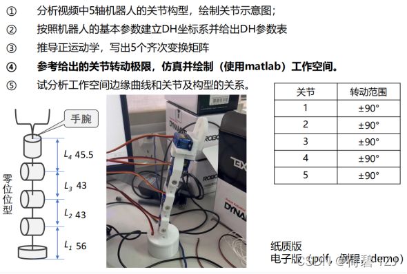
Python 机器人学 —— 机械臂工作空间分析
设关节1、关节5的高 (圆柱高) 分别为 ![]() ,5个关节的转动角分别为
,5个关节的转动角分别为 ![]()
可得出DH参数表:
| # |  |
 |
 |
 |
| 1 - 2 |  |
|||
| 2 - 3 |
|
|
||
| 3 - 4 |
|
|
||
| 4 - * |
|
|
||
| *- 5 |
|
|
||
| 5 - H |
|
|
|
因为把各个关节的坐标系位置都定在了圆柱的中心,所以需要考虑关节1、关节5的高度。其次,关节1在全局坐标系中的位置应为:![]()
根据5个关节的旋转角 + DH参数表,即可得到各个关节的坐标系,利用坐标系信息可完成图像的绘制
拟定义一个类,使其在输入5个关节的旋转角时,可完成绘制工作
环境设置
import matplotlib.pyplot as plt
import numpy as np

red = 'orangered'
orange = 'orange'
yellow = 'yellow'
green = 'greenyellow'
cyan = 'aqua'
blue = 'deepskyblue'
purple = 'mediumpurple'
pink = 'violet'

ROUND_EDGE = 30     # 圆等效多边形边数
ARRAY_TYPE = np.float   # 矩阵使用的数据类型

COMMON_HEIGHT = 20
COMMON_RADIUS_OUT = 10
COMMON_RADIUS_IN = 3
# 三个相同关节的尺寸参数
CONNECT_ROD_RADIUS = COMMON_RADIUS_OUT / 3
# 连杆外径
JOINTS_SHAPE = [[COMMON_HEIGHT * 0.8, COMMON_RADIUS_IN * 2, COMMON_RADIUS_OUT, 'Wistia_r', 10],
                [COMMON_RADIUS_OUT, COMMON_RADIUS_IN, COMMON_HEIGHT, 'cool', 2],
                [COMMON_RADIUS_OUT, COMMON_RADIUS_IN, COMMON_HEIGHT, 'cool', 2],
                [COMMON_RADIUS_OUT, COMMON_RADIUS_IN, COMMON_HEIGHT, 'cool', 2],
                [None for _ in range(5)],
                [COMMON_RADIUS_OUT * 0.8, COMMON_RADIUS_IN, COMMON_HEIGHT * 0.8, 'cool', 10]]
# 各个关节的尺寸参数
PACE_NUM = 20    # 转动范围分解步数


def DH_PARAM(theta):
    ''' DH 参数表'''
    return [[theta[0], 56 - JOINTS_SHAPE[0][2] / 2, 0, 90],    # 关节 1 -> 关节 2
            [90 + theta[1], 0, 43, 0],  # 关节 2 -> 关节 3
            [theta[2], 0, 43, 0],   # 关节 3 -> 关节 4
            [-90 + theta[3], 0, 0, -90],    # 关节 4 -> 关节 5
            [theta[4], 45.5 - JOINTS_SHAPE[-1][2] / 2, 0, 0]]
绘图函数
def figure3d():
    ''' 创建3d工作站'''
    figure = plt.subplot(projection='3d')
    figure.set_xlabel('x')
    figure.set_ylabel('y')
    figure.set_zlabel('z')
    return figure


def plot_coord_sys(state, colors=[orange, yellow, pink],
                   labels='noa', linewidth=None, length=.5):
    ''' 绘制坐标系'''
    pos = state[:3, -1]
    for idx, (c, label) in enumerate(zip(colors, labels)):
        axis = state[:3, idx] * length
        plt.plot(*zip(pos, pos + axis), c=c, label=label, linewidth=linewidth)


def cylinder(figure, state, R, h, axis, r=0, smooth=2):
    ''' 绘制圆柱
        figure: 3D工作站对象
        state: 描述坐标系的四维方阵
        R: 圆柱底面外径
        r: 圆柱底面内径
        h: 圆柱高度
        axis: 圆柱两底面圆心连线所在的轴索引
        smooth: 图像细致程度 (至少 2)
        return: 可缓存函数'''
    pos = state[:3, -1]
    if axis == 0:
        index = [0, 1, 2]
    elif axis == 1:
        index = [1, 0, 2]
    else:
        index = [2, 0, 1]
    axis, r1, r2 = map(lambda i: state[:3, i], index)
    # 主轴 + 两半径轴
    function_io = []
    # 函数流

    theta = np.linspace(0, 2 * np.pi, ROUND_EDGE, dtype=ARRAY_TYPE)
    height = np.linspace(-h / 2, h / 2, smooth, dtype=ARRAY_TYPE)
    theta, height = np.meshgrid(theta, height)
    # 角度、高度网格点

    cos_theta = np.cos(theta, dtype=ARRAY_TYPE)
    sin_theta = np.sin(theta, dtype=ARRAY_TYPE)
    hook_points = lambda radius: map(lambda i: (r1[i] * cos_theta + r2[i] * sin_theta) * radius + pos[i] + height * axis[i], range(3))
    out_ = hook_points(R)
    function_io.append(lambda cmap: figure.plot_surface(*out_, cmap=cmap))
    if r:
        in_ = hook_points(r)
        function_io.append(lambda cmap: figure.plot_surface(*in_, cmap=cmap))
        # 绘制内外曲面

    phi = np.linspace(0, 2 * np.pi, ROUND_EDGE, dtype=ARRAY_TYPE)
    radius = np.linspace(r, R, 2, dtype=ARRAY_TYPE)
    phi, radius = np.meshgrid(phi, radius)
    cos_phi = np.cos(phi, dtype=ARRAY_TYPE) * radius
    sin_phi = np.sin(phi, dtype=ARRAY_TYPE) * radius
    sub_points = lambda height: map(lambda i: r1[i] * cos_phi + r2[i] * sin_phi + pos[i] + height * axis[i], range(3))
    bottom = sub_points(-h / 2)
    function_io.append(lambda cmap: figure.plot_surface(*bottom, cmap=cmap))
    top = sub_points(h / 2)
    function_io.append(lambda cmap: figure.plot_surface(*top, cmap=cmap))
    # 绘制两底面

    def execute(cmap):
        for f in function_io:
            f(cmap)

    return execute
齐次变换矩阵
def trans(dx, dy, dz):
    ''' 齐次变换矩阵: 平移'''
    mat = np.eye(4, dtype=ARRAY_TYPE)
    mat[:3, -1] += np.array([dx, dy, dz], dtype=ARRAY_TYPE)
    return mat


def rot(theta, axis):
    ''' 齐次变换矩阵: 旋转'''
    theta = theta / 180 * np.pi
    # 角度 -> 弧度
    sin = np.sin(theta)
    cos = np.cos(theta)
    mat = np.eye(4)
    axis_idx = {'x': 0, 'y': 1, 'z': 2}
    if isinstance(axis, str):
        axis = axis_idx[axis]
        # 字符 -> 空间轴名称
    if axis == 0:
        mat[1: 3, 1: 3] = np.array([[cos, -sin],
                                    [sin, cos]], dtype=ARRAY_TYPE)
    elif axis == 1:
        mat[:3, :3] = np.array([[cos, 0, sin],
                                [0, 1, 0],
                                [-sin, 0, cos]], dtype=ARRAY_TYPE)
    elif axis == 2:
        mat[:2, :2] = np.array([[cos, -sin],
                                [sin, cos]], dtype=ARRAY_TYPE)
    else:
        raise AssertionError(f'axis: {axis_idx}')
    return mat
机械臂对象
每次工作状态改变时 (即机械臂运动),保存机械臂末端的点坐标,绘制成工作空间。在这个过程中,通过 numpy 判断新的工作点是否与旧的工作点重叠,并只保存不重叠的工作点
class Robot_Arm:
    ''' 机械臂对象'''
    fig = figure3d()
    state = np.eye(4, dtype=ARRAY_TYPE) @ trans(0, 0, JOINTS_SHAPE[0][2] / 2)

    def __init__(self):
        self.restart()

    def restart(self):
        ''' 重启工作空间记录器'''
        self.work_space = np.ones([0, 3])

    def refresh(self, theta=[0] * 5):
        ''' 根据旋转角度刷新画面'''
        joints = self.search(theta)
        plt.cla()
        # 清空画布
        self.fig.view_init(elev=5, azim=-90)
        for set_ in self.fig.set_xlim3d, self.fig.set_ylim3d:
            set_(-150, 150)
        self.fig.set_zlim3d(-50, 200)
        plt.tight_layout()
        # 设置 3D 工作站边界
        for (R, r, h, cmap, smooth), joint in zip(JOINTS_SHAPE, joints):
            if R:
                cylinder(self.fig, joint, R=R, r=r, h=h, axis=2, smooth=smooth)(cmap)
                plot_coord_sys(joint, linewidth=2, length=30)
                # 绘制关节及其坐标系
        for axis, length, rear in zip([1, 0, 0, None, 2], [56, 43, 43, 0, 45.5], joints[1:]):
            if length:
                move = -length / 2
                connect_rod = rear @ trans(*map(lambda i: (axis == i) * move, range(3)))
                cylinder(self.fig, connect_rod, CONNECT_ROD_RADIUS, length, axis=axis)('winter_r')
                # 绘制连杆
        tail = joints[-1] @ trans(0, 0, JOINTS_SHAPE[-1][2] / 2)
        tail = tail[:3, -1].reshape(1, -1)
        if np.all(((tail - self.work_space) ** 2).sum(axis=1) > 18):
            self.work_space = np.append(self.work_space, tail, axis=0)
            # 检测新工作点是否与旧工作点重叠
        self.fig.scatter(*map(lambda i: self.work_space[:, i], range(3)), c=red, alpha=0.4, s=10)
        plt.pause(0.001)

    def search(self, theta):
        ''' 搜索关节的位置'''
        joints = [self.state]
        for rot_z, trans_z, trans_x, rot_x in DH_PARAM(theta):
            last_joint = joints[-1]
            cur_joint = last_joint @ rot(rot_z, axis='z') @ trans(trans_x, 0, trans_z) @ rot(rot_x, axis='x')
            joints.append(cur_joint)
        return joints
工作空间绘制
def draw_work_space():
    ''' 工作空间绘制'''
    out_points = []
    in_points = []
    for t in THETA:
        theta = [0 for _ in range(5)]
        theta[1] = t
        arm.refresh(theta)
    out_points.append(arm.work_space)
    # 绘制外圆上半部分
    for c in 90, -90:
        arm.restart()
        for t in THETA:
            arm.refresh([0, c, t, 0, 0])
        out_points.append(arm.work_space)
        # 绘制外圆下半部分
    for c in 90, -90:
        arm.restart()
        for t in THETA:
            arm.refresh([0, c, c, t, 0])
        out_points.append(arm.work_space)
        # 绘制外圆中下部分
    for c in 90, -90:
        arm.restart()
        for t in THETA:
            arm.refresh([0, t, c, c, 0])
        in_points.append(arm.work_space)
        # 绘制内圆
    arm.restart()
    arm.refresh()
    for line in out_points + in_points:
        loc = list(map(lambda i: line[:, i], range(3)))
        arm.fig.plot(*loc, c=red, linewidth=2, alpha=0.7)
        arm.fig.scatter(*loc, c=red, alpha=0.4, s=10)
        # 绘制轨迹


arm = Robot_Arm()
# 初始化机械臂
draw_work_space()
# 绘制工作空间
plt.pause(0)
最终结果
当5个关节的转动角均为0时,机械臂处在工作原点 (如下图所示)。对于这5个旋转关节而言,其z轴 (粉色轴) 均处在其右手规则旋转的方向上;其x轴 (橙色轴) 均处在其z轴与上一个关节的z轴的公垂线方向上,满足DH表示法的要求

当机械臂的5个转角分别为 [0, ![]() , 0, 0, 0] 时,其工作点分布在
, 0, 0, 0] 时,其工作点分布在 ![]() 的圆内
的圆内

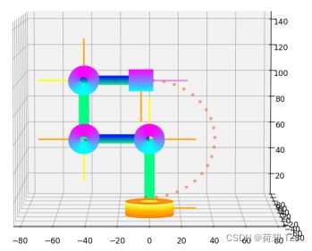
当机械臂的5个转角分别为 [0, ![]() , -90, -90, 0] 时,可绘制出如下工作点。取
, -90, -90, 0] 时,可绘制出如下工作点。取 ![]() 进行计算,半径
进行计算,半径 ![]()
当机械臂的5个转角分别为 [0, -90, ![]() , 0, 0] 时,其工作点分布在
, 0, 0] 时,其工作点分布在 ![]() 的圆内
的圆内

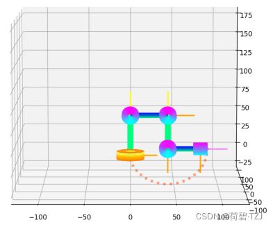
当机械臂的5个转角分别为 [0, -90, -90, ![]() , 0] 时,其工作点分布在
, 0] 时,其工作点分布在 ![]() 的圆内
的圆内
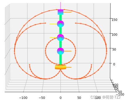
将所有范围叠加,得到工作空间的边界如下: