从零编写linux0.11 - 第五章 中断与异常
编程环境:Ubuntu Kylin 16.04、gcc-5.4.0
代码仓库:https://gitee.com/AprilSloan/linux0.11-project
linux0.11源码下载(不能直接编译,需进行修改)
本章目标
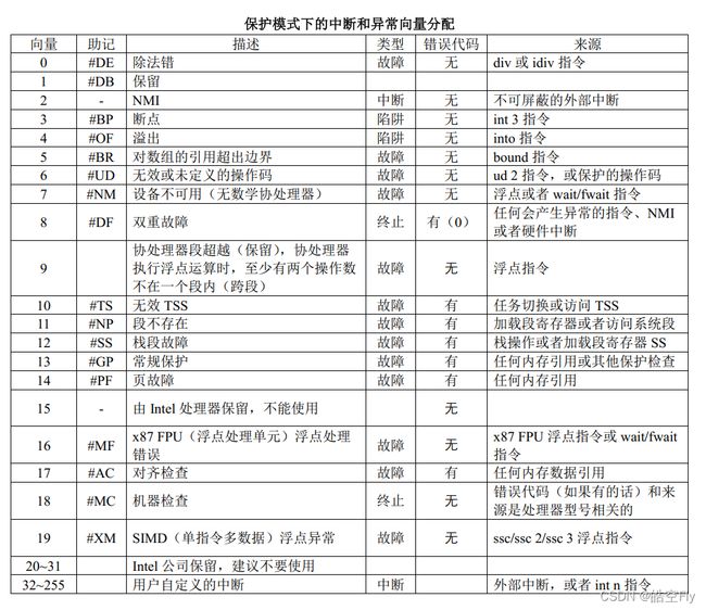
本章会编写部分异常的处理函数以及初始化PIC(可编程中断控制器)。下图是中断异常向量分配表,本章会编写0-6、8-13、15、17-20号异常处理函数,根据有无错误代码,将异常分为两类,我们会先编写无错误代码的异常处理函数,再编写有错误代码的异常处理函数。7和16号异常向量与协处理器相关,代码结构与之前的异常处理函数不同,会在之后的章节编写。14号异常向量是缺页中断,会在内存管理的章节编写。
1.除零异常
除零异常顾名思义除以0就会触发这个异常。
那操作系统应该怎么检测是否有除零操作?老实说,这个检测操作不归操作系统管,这属于硬件处理的范畴。CPU一旦检查出有除零操作,就跳转到固定地址处理这个异常。
那么,这个固定地址又在哪儿呢?你是否还记得idt(中断描述符表),idt可以保存异常处理函数的地址。通过加上一个偏移就可以找到不同异常处理函数的地址,如除零异常的偏移为0,断点的偏移为24(每个中断描述符的大小为8字节)。
CPU是怎么找到idt的?idt定义在head.s中,它的地址确实也不是什么特殊地址,但我们可以通过lidt这个命令将idt的地址加载到 idtr(专门保存idt地址的寄存器)中。CPU只要访问 idtr 就可以找到idt的地址了。
idt的结构体是怎样的呢?
| 字段 | 含义 |
|---|---|
| 段选择器 | 中断处理程序所在的段选择符 |
| TYPE | 描述符的类型。1110:中断描述符; 0101:任务门描述符; 1111:陷阱门描述符(异常) |
| 偏移 | 中断处理程序所在段的段内偏移 |
| DPL | 表示描述符的特权级。处理器支持的特权级别有4种,分别是0,1,2,3,其中0是最高特权级别。 |
| P | 段存在位,用于表示描述符所对应的段是否存在。 P=0,表示段不在内存中;P=1,表示段在内存中。 |
原理已经说明,现在来看看如何将异常处理函数地址放入idt中。下面三段代码分别来自traps.c,system.h和head.h。
// traps.c
void trap_init(void)
{
set_trap_gate(0, ÷_error);
}
// system.h
#define _set_gate(gate_addr, type, dpl, addr) \
__asm__("movw %%dx, %%ax\n\t" \
	"movw %0, %%dx\n\t" \
	"movl %%eax, %1\n\t" \
	"movl %%edx, %2" \
	: \
	:"i"((short) (0x8000 + (dpl << 13) + (type << 8))), \
	"o"(*((char *) (gate_addr))), \
	"o"(*(4 + (char *) (gate_addr))), \
	"d"((char *) (addr)),"a"(0x00080000))

#define set_trap_gate(n, addr) \
	_set_gate(&idt[n], 15, 0, addr)
#ifndef _HEAD_H_
#define _HEAD_H_

typedef struct desc_struct {
	unsigned long a, b;
} desc_table[256];

extern desc_table idt, gdt;	// 定义在head.s中

#endif
要理解代码,需要对照着idt的结构来阅读。这里主要需要阅读system.h的代码。gate_addr表示idt[0](0号向量)的地址;type的值为15,代表这是一个陷阱门描述符,也就是异常;dpl的值为0,代表该异常处理函数有最高权限;addr代表异常处理函数的地址,放入偏移字段,但偏移字段并不是32位连续的,所以要进行一些特别的处理。第3-6行将不同的数据放到相应的字段中,这个步骤应该不是太难理解。
接下来看看异常处理函数的代码。以下是asm.s的内容。
.globl divide_error

divide_error:
	pushl $do_divide_error
no_error_code:
	xchgl %eax, (%esp)
	pushl %ebx
	pushl %ecx
	pushl %edx
	pushl %edi
	pushl %esi
	pushl %ebp
	push %ds
	push %es
	push %fs
	pushl $0		# "error code"
	lea 44(%esp), %edx
	pushl %edx
	movl $0x10, %edx
	mov %dx, %ds
	mov %dx, %es
	mov %dx, %fs
	call *%eax
	addl $8, %esp
	pop %fs
	pop %es
	pop %ds
	popl %ebp
	popl %esi
	popl %edi
	popl %edx
	popl %ecx
	popl %ebx
	popl %eax
	iret
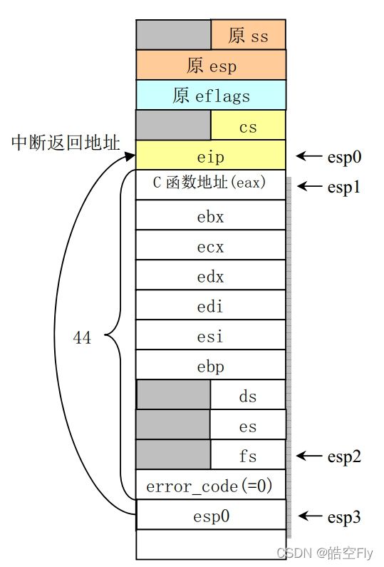
可以看到,函数中大多都是寄存器出栈入栈操作,这是为了保存中断现场,其具体的堆栈变化如下图所示。eip及其上的寄存器都是由硬件自动入栈的,异常处理结束后,也会由硬件自动出栈。剩下的寄存器和数值都是由异常处理函数入栈的。刚进入divide_error的时候,esp位于esp0的位置。执行了pushl $do_divide_error之后,esp位于esp1的位置。执行了push %fs之后,esp位于esp2的位置。执行了pushl %edx之后,esp位于esp3的位置,edx中保存的是esp0的地址。最后两个入栈的数会作为do_divide_error的参数。之后要更改段寄存器的值,后面的章节我们会进入用户态,而用户态的段寄存器并不是0x10。
xchgl %eax, (%esp)会将eax的值与栈中do_divide_error的地址互换。call *%eax会执行do_divide_error函数。在执行完do_divide_error后,将栈中的内容依次出栈。最后使用iret退出异常。
do_divide_error定义在traps.c中。
#include do_divide_error会调用die函数打印异常名和出错码,并把出错信息打印出来。do_divide_error的第一个参数是esp0的地址,所以esp[0]是eip,esp[1]是cs,其它的以此类推。原本除零异常后,会清理内存,关闭进程打开的文件,切换进程,但是这些东西我们都没有,就只好死循环了。另外,不要忘记声明divide_error函数,不然编译时会报错。
修改kernel下的Makefile,把文件添加到目标中。
OBJS =sched.o traps.o asm.o printk.o vsprintf.o mktime.o
在sched.h中添加函数申明,包含head.h。
#ifndef _SCHED_H_
#define _SCHED_H_
#include 最后修改main函数,看看我们的异常处理函数是否能正常运行。
void main(void)
{
	int x = 0;
	memory_end = (1 << 20) + (EXT_MEM_K << 10);
	memory_end &= 0xfffff000;
	if (memory_end > 16 * 1024 * 1024)
		memory_end = 16 * 1024 * 1024;
	if (memory_end > 12 * 1024 * 1024)
		buffer_memory_end = 4 * 1024 * 1024;
	else if (memory_end > 6 * 1024 * 1024)
		buffer_memory_end = 2 * 1024 * 1024;
	else
		buffer_memory_end = 1 * 1024 * 1024;
	main_memory_start = buffer_memory_end;
	mem_init(main_memory_start, memory_end);
	trap_init();
	tty_init();
	time_init();
	buffer_init(buffer_memory_end);
	x = 1 / x;
	printk("x = %d\n\r", x);
	cli();
	while (1);
}
注意,如果没有printk("x = %d\n\r", x);这一行代码的话,不会触发除零异常,因为编译器会把x = 1 / x;这行代码当作无用的东西优化掉。
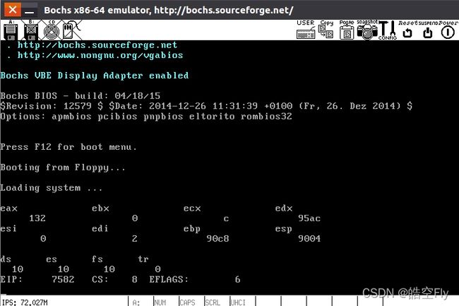
下面是运行结果。
可以看到我们确实触发了除零异常,但是栈段寄存器和段指针寄存器的值有点不对劲,怎么都是0啊?这是因为程序是从核心态进入异常,栈段寄存器和段指针寄存器不发生改变,所以没入栈。如果是从用户态进入除零异常就不会出现这种情况。虚惊一场,我在网上找了好久的资料,最后还是同学告诉我是怎么回事,还好没问题,进入下一节吧!
2.其他一些无错误码的异常
这节的异常处理函数与上一节的结构相似,这一节的内容真的毫无难度。
以下是asm.s的内容。
.globl divide_error, debug, nmi, int3, overflow, bounds, invalid_op
.globl coprocessor_segment_overrun
.globl reserved

debug:
	pushl $do_int3		# _do_debug
	jmp no_error_code

nmi:
	pushl $do_nmi
	jmp no_error_code

int3:
	pushl $do_int3
	jmp no_error_code

overflow:
	pushl $do_overflow
	jmp no_error_code

bounds:
	pushl $do_bounds
	jmp no_error_code

invalid_op:
	pushl $do_invalid_op
	jmp no_error_code

coprocessor_segment_overrun:
	pushl $do_coprocessor_segment_overrun
	jmp no_error_code

reserved:
	pushl $do_reserved
	jmp no_error_code
这些异常处理函数都是把函数的地址入栈然后跳转到no_error_code。
下面是traps.c的内容。
#include 除了do_int3是打印信息以外,其它的都是调用die函数。稍微不同的就是3、4、5号异常向量,用set_system_gate设置异常。set_system_gate函数的定义在system.h中。
#define set_trap_gate(n, addr) \
	_set_gate(&idt[n], 15, 0, addr)

#define set_system_gate(n,addr) \
	_set_gate(&idt[n], 15, 3, addr)
可以发现它与set_trap_gate函数差别不大,3代表将此异常的特权等级设置为3,特权等级3是用户级,是操作系统最低的等级,无论哪个用户都能使用它。虽然17号中断有错误码,但因为都是reserved函数,我就一起设置了。
最后修改main函数,触发断点异常。
void main(void)
{
	memory_end = (1 << 20) + (EXT_MEM_K << 10);
	memory_end &= 0xfffff000;
	if (memory_end > 16 * 1024 * 1024)
		memory_end = 16 * 1024 * 1024;
	if (memory_end > 12 * 1024 * 1024)
		buffer_memory_end = 4 * 1024 * 1024;
	else if (memory_end > 6 * 1024 * 1024)
		buffer_memory_end = 2 * 1024 * 1024;
	else
		buffer_memory_end = 1 * 1024 * 1024;
	main_memory_start = buffer_memory_end;
	mem_init(main_memory_start, memory_end);
	trap_init();
	tty_init();
	time_init();
	buffer_init(buffer_memory_end);
	__asm__("int $0x3"::);	// 触发断点异常
	cli();
	while (1);
}
虽然打印信息格式看起来不太舒服,但是确实是出发了异常。其它的异常大家可以自己试着触发。
下一节会介绍有错误码的异常处理函数的处理过程。
3.双重故障
双重故障(double fault)是最靠前的有错误码的异常向量,这一节会以它为例,讲解有错误的异常处理函数的处理过程。
首先给出代码,下面是asm.s的内容。
double_fault:
	pushl $do_double_fault
error_code:
	xchgl %eax, 4(%esp)		# error code <-> %eax
	xchgl %ebx, (%esp)		# &function <-> %ebx
	pushl %ecx
	pushl %edx
	pushl %edi
	pushl %esi
	pushl %ebp
	push %ds
	push %es
	push %fs
	pushl %eax			# error code
	lea 44(%esp), %eax		# offset
	pushl %eax
	movl $0x10, %eax
	mov %ax, %ds
	mov %ax, %es
	mov %ax, %fs
	call *%ebx
	addl $8, %esp
	pop %fs
	pop %es
	pop %ds
	popl %ebp
	popl %esi
	popl %edi
	popl %edx
	popl %ecx
	popl %ebx
	popl %eax
	iret
上面的代码还请对照下面的图进行理解。在刚进入double_fault,还没执行入栈操作之前,esp位于esp0的位置。将do_double_fault地址入栈后,esp位于esp1位置处。第4-5行代码将eax的值与栈中的error_code向交换,将ebx的值与do_double_fault地址相交换,随后将一系列寄存器入栈。然后将错误码和栈内eip的地址入栈作为do_double_fault函数的参数。更改段寄存器为系统数据段,调用do_double_fault函数,之后将入栈的寄存器出栈,退出异常。
do_double_fault函数也是调用die函数打印信息然后死循环。以下是traps.c的内容。
void do_double_fault(long esp, long error_code)
{
	die("double fault",esp,error_code);
}
有了第一节的基础,相信这些内容都不难理解。
也正是有了第一节的内容,这一节都没什么好讲的了,就顺便把其他的有错误码的异常处理函数写出来吧。
下面分别是asm.s和traps.c的内容。
.globl divide_error,debug,nmi,int3,overflow,bounds,invalid_op
.globl double_fault,coprocessor_segment_overrun
.globl invalid_TSS,segment_not_present,stack_segment
.globl general_protection,reserved

invalid_TSS:
	pushl $do_invalid_TSS
	jmp error_code

segment_not_present:
	pushl $do_segment_not_present
	jmp error_code

stack_segment:
	pushl $do_stack_segment
	jmp error_code

general_protection:
	pushl $do_general_protection
	jmp error_code
void divide_error(void);
void debug(void);
void nmi(void);
void int3(void);
void overflow(void);
void bounds(void);
void invalid_op(void);
void double_fault(void);
void coprocessor_segment_overrun(void);
void invalid_TSS(void);
void segment_not_present(void);
void stack_segment(void);
void general_protection(void);
void reserved(void);
void do_general_protection(long esp, long error_code)
{
die("general protection",esp,error_code);
}
void do_invalid_TSS(long esp,long error_code)
{
die("invalid TSS",esp,error_code);
}
void do_segment_not_present(long esp,long error_code)
{
die("segment not present",esp,error_code);
}
void do_stack_segment(long esp,long error_code)
{
die("stack segment",esp,error_code);
}
void trap_init(void)
{
int i;
set_trap_gate(0, ÷_error);
set_trap_gate(1, &debug);
set_trap_gate(2, &nmi);
set_system_gate(3, &int3); /* int3-5 can be called from all */
set_system_gate(4, &overflow);
set_system_gate(5, &bounds);
set_trap_gate(6, &invalid_op);
set_trap_gate(8, &double_fault);
set_trap_gate(9, &coprocessor_segment_overrun);
set_trap_gate(10, &invalid_TSS);
set_trap_gate(11, &segment_not_present);
set_trap_gate(12, &stack_segment);
set_trap_gate(13, &general_protection);
set_trap_gate(15, &reserved);
for (i = 17; i < 20; i++)
set_trap_gate(i, &reserved);
}
最后还是修改main函数触发异常看看吧。
void main(void)
{
	memory_end = (1 << 20) + (EXT_MEM_K << 10);
	memory_end &= 0xfffff000;
	if (memory_end > 16 * 1024 * 1024)
		memory_end = 16 * 1024 * 1024;
	if (memory_end > 12 * 1024 * 1024)
		buffer_memory_end = 4 * 1024 * 1024;
	else if (memory_end > 6 * 1024 * 1024)
		buffer_memory_end = 2 * 1024 * 1024;
	else
		buffer_memory_end = 1 * 1024 * 1024;
	main_memory_start = buffer_memory_end;
	mem_init(main_memory_start, memory_end);
	trap_init();
	tty_init();
	time_init();
	buffer_init(buffer_memory_end);
	printk("Commenting cli will trigger double fault exception!\r\n");
	// cli();
	while (1);
}
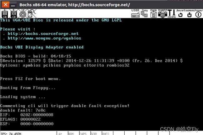
在使用了printk函数后没有加cli函数会导致双重故障。我推测是因为printk函数中会开启中断,这时系统会接收到中断并触发中断处理函数,但我们并没有初始化PIC,也没有写中断处理函数,所以导致双重故障。不负所望,果然报错了。
4.PIC初始化
本来linux0.11会在setup.s中初始化PIC,但是本着把相近的功能放在同一章节的原则,直到现在我才初始化PIC。
可编程中断控制器(Programmable Interrupt Controller),简称PIC,是一种管理中断请求的设备。在x86中,采用8259A可编程中断控制器芯片,每个芯片可以管理8个中断,而通过级联的方式,可以增加管理的数量。下图是两篇8259A级联的示意图,在这种情况下,可以管理15个中断(主片7个,从片8个)。
下面还是看看traps.c中的代码。
#include 这是一系列的端口操作,右边的数字是端口号,左边是要向端口发送的数字。虽然我在旁边写了注释,但是还是很懵对不对?懵就对了,不然我讲什么。
首先让我们看看端口号,这里一共用到了四个端口:0x20、0x21、0xa0、0xa1。这四个端口的用处是什么呢?查查这个网页ports,可以看到:
0x20和0x21端口属于8259A主片,可以通过这两个端口对主片进行设置。0xa0和0xa1端口属于8259从片,同样可以通过这两个端口对从片进行设置。
现在来看看向端口发送的数字有什么含义,这个网页8259有详细的说明,当然我也会进行说明。
0x20和0xa0有ICW1寄存器(初始化控制字1),0x21和0xa1有ICW2、ICW3、ICW4和OCW1(操作控制字1)。在初始化PIC时,我们要按照ICW1、ICW2、ICW3、ICW4的顺序写寄存器。你可能会问ICW2、ICW3、ICW4寄存器在同一端口,怎么区分呢?当设置了ICW1后,芯片会自动将数据传给相应的寄存器,不需要我们操心。这些寄存器的结构如下。
ICW1
| 位 | 名称 | 含义 |
|---|---|---|
| D7 | A7 | 这几位对8086/88处理器无用。 |
| D6 | A6 | 这几位对8086/88处理器无用。 |
| D5 | A5 | 这几位对8086/88处理器无用。 |
| D4 | 1 | 恒为1。 |
| D3 | LTIM | 0 - 边沿触发方式; 1 - 电平触发中断方式。 |
| D2 | ADI | 对8086/88系统无用。 |
| D1 | SNGL | 0 - 多片8259A芯片; 1 - 单片8259A芯片。 |
| D0 | IC4 | 0 - 不需要ICW4; 1 - 需要ICW4。 |
当发送的字节第5比特位(D4)=1,端口地址为0x20或0xa0时,表示对ICW1进行操作。我们将ICW1设置为0x11,表示中断请求是边沿触发,多片8259A芯片级联且需要发送ICW4。
ICW2
| 位 | 名称 | 含义 |
|---|---|---|
| D7 | A15/T7 | 在使用8086/88处理器的系统或兼容系统中,T7-T3是中断号的高5位,与8259A芯片自动设置的低3位(8259A按IR0-IR7三维编码值自动填入)组成一个8位中断号。8259A在收到第2个中断响应脉冲时,把此中断号送到数据线上,以供CPU读取。 |
| D6 | A14/T6 | |
| D5 | A13/T5 | |
| D4 | A12/T4 | |
| D3 | A11/T3 | |
| D2 | A10 | 一般都设置为0 |
| D1 | A9 | 一般都设置为0 |
| D0 | A8 | 一般都设置为0 |
我们把主片的ICW2设置为0x20,表示主片中断请求0-7对应的中断号是0x20-0x27,把从片的ICW2设置成0x28,表示从片中断请求8-15级对应的中断号是0x28-0x2f。另外0x00-0x1f的中断号要么是系统异常中断,要么就是Intel预留给以后使用的,反正我们是不能使用的。
ICW3
| 位 | D7 | D6 | D5 | D4 | D3 | D2 | D1 | D0 |
|---|---|---|---|---|---|---|---|---|
| 主片 | S7 | S6 | S5 | S4 | S3 | S2 | S1 | S0 |
| 从片 | 0 | 0 | 0 | 0 | 0 | ID2 | ID1 | ID0 |
对于主片,Si=1表示IRi与从片级联,则该中断请求引脚的信号来自从片。
对于从片,ID2-ID0三个比特位对应个从片的标识号,即连接到主片的中断级。当某个从片接收到级联线(CAS2-CAS0)输入的值与自己的ID2-ID0相等时,从片应该向数据总线发送自己当前被选中的中断请求的中断号。
我们把主片的ICW3设置为0x04,即S2=1,其余各位为0,表示主片的IR2连接一个从片,从片的ICW3被设置为0x02,即其标识号为2,表示此从片连接到主片的IR2引脚。因此,中断优先级的排列次序为:0级最高,1级次之,接下来是8-15级,最后是主片的3-7级。
ICW4
| 位 | 名称 | 含义 |
|---|---|---|
| D7 | 0 | 恒为0 |
| D6 | 0 | |
| D5 | 0 | |
| D4 | SFNM | 0 - 普通全嵌套方式 1 - 特殊全嵌套方式 |
| D3 | BUF | 0 - 非缓冲方式 1 - 缓冲方式 |
| D2 | M/S | 0 - 缓冲方式下从片 1 - 缓冲方式下主片 |
| D1 | AEOI | 0 - 非自动结束中断方式 1 - 自动结束中断方式 |
| D0 | MPM | 0 - MCS80/85系统 1 - 8086/88处理器系统 |
我们把主片和从片的ICW4都被设置为0x01。表示设置为普通全嵌套方式、非缓冲方式、非自动结束中断方式,并用于8086及其兼容机。
OCW1
| 位 | D7 | D6 | D5 | D4 | D3 | D2 | D1 | D0 |
|---|---|---|---|---|---|---|---|---|
| 名称 | M7 | M6 | M5 | M4 | M3 | M2 | M1 | M0 |
这个寄存器用于对8259A中IMR(中断屏蔽寄存器)进行读写操作。若Mi=1,则屏蔽对应的中断请求级IRi;若Mi=0,则允许IRi。另外,屏蔽高优先级中断并不会影响低优先级中断的请求。我们将主片和从片的OCW1都设置为0xff,表示屏蔽所有的中断。
这一小段代码牵扯了很多内容呢。
在trap_init中调用pic_init函数,并将中断服务函数都设置为reserved,之后再对每个中断进行设置。顺便将die函数中的cli删掉。
static void die(char *str, long esp_ptr, long nr)
{
long *esp = (long *) esp_ptr;
int i;
printk("%s: %04x\n\r",str, nr & 0xffff);
printk("EIP:\t%04x:%p\n\rEFLAGS:\t%p\n\rESP:\t%04x:%p\n\r",
esp[1], esp[0], esp[2], esp[4], esp[3]);
while (1);
}
void trap_init(void)
{
int i;
pic_init();
set_trap_gate(0, ÷_error);
set_trap_gate(1, &debug);
set_trap_gate(2, &nmi);
set_system_gate(3, &int3); /* int3-5 can be called from all */
set_system_gate(4, &overflow);
set_system_gate(5, &bounds);
set_trap_gate(6, &invalid_op);
set_trap_gate(8, &double_fault);
set_trap_gate(9, &coprocessor_segment_overrun);
set_trap_gate(10, &invalid_TSS);
set_trap_gate(11, &segment_not_present);
set_trap_gate(12, &stack_segment);
set_trap_gate(13, &general_protection);
set_trap_gate(15, &reserved);
for (i = 17; i < 48; i++)
set_trap_gate(i, &reserved);
}
修改main.c,编译运行。
void main(void)
{
	memory_end = (1 << 20) + (EXT_MEM_K << 10);
	memory_end &= 0xfffff000;
	if (memory_end > 16 * 1024 * 1024)
		memory_end = 16 * 1024 * 1024;
	if (memory_end > 12 * 1024 * 1024)
		buffer_memory_end = 4 * 1024 * 1024;
	else if (memory_end > 6 * 1024 * 1024)
		buffer_memory_end = 2 * 1024 * 1024;
	else
		buffer_memory_end = 1 * 1024 * 1024;
	main_memory_start = buffer_memory_end;
	mem_init(main_memory_start, memory_end);
	trap_init();
	tty_init();
	time_init();
	buffer_init(buffer_memory_end);
	printk("Now printk won't trigger exception!\r\n");
	while (1);
}
之前在main函数中添加cli是因为没有中断处理函数,现在不会再触发double fault了。
不错,解决了一个小bug。下一章我准备开始进程管理的内容。


