NMOS与PMOS的区分及使用
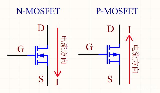
1、箭头指向栅极G的为NMOS,反之为PMOS
2、箭头的方向代表了电子的运动方向,电流方向与之相反
3、P Channel mosfet current direction
源極的源是指載流子的起點;漏極的漏是指載流子的終點。載流子從源極出發,穿過溝道,到達漏極,從外部看,載流子最終從漏極漏出去了。顯然,NMOS和PMOS的載流子是不同的,因此導致了令人困惑的電流方向問題。盯住載流子即可,別被電流方向迷惑。
可以簡單地認為,柵極和襯底間的電壓超過閾值後,漏極和源極就接通了,而電流大小則是由柵漏源三極間的電壓決定。因為MOS是對稱結構,所以源極和漏極無區別且可互換。
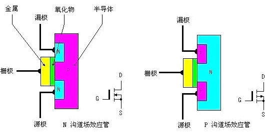
關於D和S,也就是漏和源,其實是從工藝角度觀察的結果。在MOS中,有兩種載流子,一種是電子,另一種是空穴,標記為N和P。顯然,NMOS的載流子是電子,PMOS的載流子是空穴。NMOS導通後,電子從源極進入溝道,從漏極離開。因為電子的運動方向與電流方向相反,所以電流從NMOS的漏極流向源極。相反地,在PMOS中,雖然空穴也是從源極進入溝道,從漏極離開,但空穴的運動方向與電流方向一致。因此,電流從PMOS的源極流向漏極。
![]()
![]()
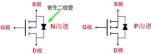
上图出现的二极管为体二极管,在驱动感性负载(马达)时很重要
NMOS是栅极高电平(|VGS| > Vt)导通,低电平断开,可用来控制与地之间的导通。
PMOS是栅极低电平(|VGS| > Vt)导通,高电平断开,可用来控制与电源之间的导通。
NMOS因Source端一般接地(低电位),所以要让|VGS| > Vt, 则Gate端一般要接正电压,这样管子才能导通;
PMOS因Source端一般接VDD(高电平),所以要让|VGS|>Vt,则Gate端一般要接负电压(低与VDD的电压),这样管子才能导通。
4、PMOS开关电路
设计电路
设计并调试好的电路如下图所示,由于供电电压和驱动电压均可以使用12V,所以采用了如下较为简单的方案。
![]()
如图所示,Q9 AO3401的栅极(G)通过100k电阻上拉到12V,源级(S)直接连接至12V电源侧,漏极(D)连接到被控设备,被控设备两端并联二极管,用于关断设备后,释放被控设备上的能量。在默认情况下,Q9 A03401的栅极被拉到12V,此时Vgs=0,PMOS处于截止状态,被控设备关断。
控制逻辑如下:
| 信号 |
动作 |
| Control_Signal=1 |
被控设备得电 |
| Control_Signal=0 |
被控设备掉电,并通过续流二极管D8释放存储的能量 |
5、 An example of using the MOSFET as a switch
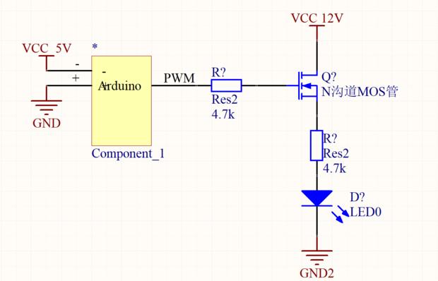
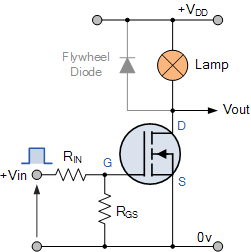
In this circuit arrangement an Enhancement-mode N-channel MOSFET is being used to switch a simple lamp “ON” and “OFF” (could also be an LED).
The gate input voltage VGS is taken to an appropriate positive voltage level to turn the device and therefore the lamp load either “ON”, ( VGS = +ve ) or at a zero voltage level that turns the device “OFF”, ( VGS = 0V ).
If the resistive load of the lamp was to be replaced by an inductive load such as a coil, solenoid or relay a “flywheel diode” would be required in parallel with the load to protect the MOSFET from any self generated back-emf.
6、P-channel MOSFET Switch
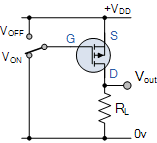
In some applications we require the use of P-channel enhancement-mode MOSFET where the load is connected directly to ground. In this instance the MOSFET switch is connected between the load and the positive supply rail (high-side switching) as we do with PNP transistors.
In a P-channel device the conventional flow of drain current is in the negative direction so a negative gate-source voltage is applied to switch the transistor “ON”.
This is achieved because the P-channel MOSFET is “upside down” with its source terminal tied to the positive supply +VDD. Then when the switch goes LOW, the MOSFET turns “ON” and when the switch goes HIGH the MOSFET turns “OFF”.
This upside down connection of a P-channel enhancement mode MOSFET switch allows us to connect it in series with a N-channel enhancement mode MOSFET to produce a complementary or CMOS switching device as shown across a dual supply.
