TOF,双目,结构光,激光雷达等传感器及相关技术
导论
https://blog.csdn.net/ds1130071727/article/details/89303021

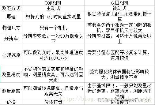
若已经有匹配好的点对,要根据点对估计相机的运动,可以分为以下三种情况:

2D-2D:即点对都是2D点,比如单目相机匹配到的点对。我们可以用对极几何来估计相机的运动。在估计完相机运动之后,我们还可以用三角测量(Triangulation)来估计特征点的空间位置(包括深度)。注意,是估计相机之间的运动。

3D-2D:点对一组为3D,一组为2D,可以通过PnP求解。注意,是估计相机的位姿。

3D-3D:通过双目或RGB-D或者某种方式得到了空间点的深度,即得到两组3D点,常用ICP解决。
一、 RGBD 相机 (高分辨率RGB + 低分辨率深度相机)
RGB相机与深度相机标定
https://blog.csdn.net/yaked/article/details/53125819

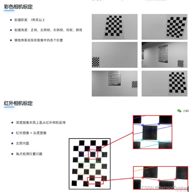
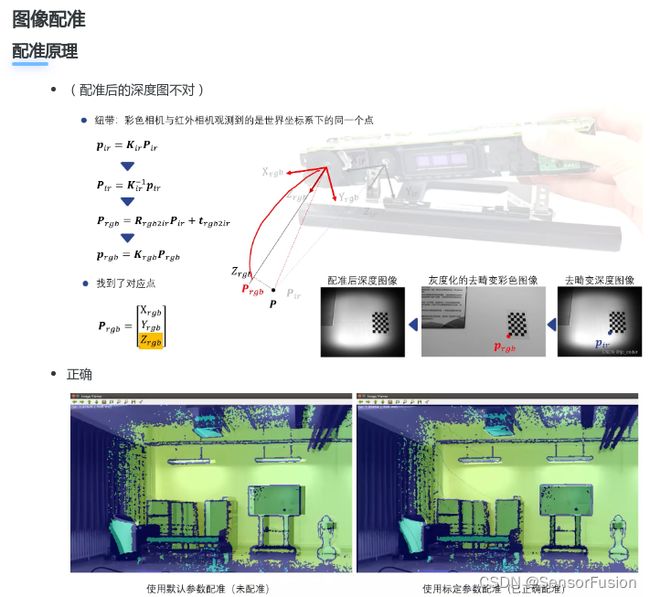
深度图与RGB标定原理
方法一:2d-2d (这样不准,视角差)
利用rgb与ir 图进行标定,2d-2d关系,利用本质矩阵求解出外参
方法二: 3d-2d
利用rgb与深度图产生的 3d点云进行标定,3d-2d关系,利用pnp求解出外参
方法三: 单组 双目标定思路
深度图与RGB标定原理
利用标定板的空间点P
求解出: 棋盘相对于深度摄像头外参矩阵 matlab
求解出: 棋盘相对于RGB摄像头外参矩阵 matlab
利用间接关系,求解出 深度摄像头和RGB摄像头外参矩阵 公式
验证:
from numpy import *
import numpy as np
# import matplotlib.pylab as plt


#双目内参
# ir camera
# 408.72767  0           332.18622
# 0        410.38278    227.32216
# 0        0             1
#
# rgb camera
# 438.63884  0      337.13761
# 0          440.86391   254.91443
# 0         0             1
#


ir_in = np.loadtxt("ir_matlab_intrinsic.txt")
rgb_in = np.loadtxt("rgb_matlab_intrinsic.txt")

# RT矩阵
R = np.array([[0.9996,    0.0289,    0.0006], [-0.0289,    0.9983,   -0.0513], [-0.0021,    0.0512,    0.9987]])
T = np.array([[-54.58182],   [2.11322],  [-0.64764]])

print (R)
print (T)
# ir 内参逆阵
ir_in_I = linalg.inv(ir_in)
print (ir_in_I)

# 建立ir像面坐标,900指某一点的深度900mm,注意是 Zc [x  y 1]
pixel_depth = 900
test = np.array([[129 * pixel_depth], [302 * pixel_depth], [pixel_depth]])

print ("---- Pir ---")
P_ir = np.dot(ir_in_I, test)
print (P_ir)
P_rgb = np.dot(R, P_ir) + T
print ("---- P rgb ---")
print (P_rgb)
p_rgb = np.dot(rgb_in, P_rgb)

print (p_rgb)
print (p_rgb / p_rgb[2])
目前比较常见的深度摄像头有tof(飞行时间测量)摄像头与结构光摄像头,对带这两种摄像头的rgbd相机,外参数标定方法有两种:
1.使用rgb图和ir图进行标定
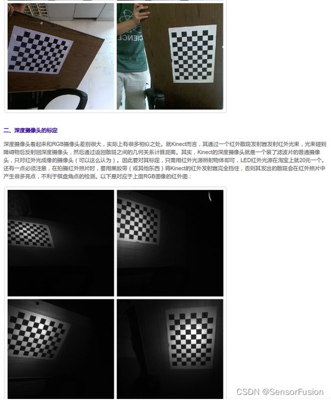
对于带有红外摄像头进行深度测量的深度摄像头,会传输出一张ir图,用户使rgbd相机对准一张棋盘格图像,使ir图和rgb图都获取到该棋盘格图像,再在这两帧图中用棋盘格特征点的查找方法标记出各自的棋盘格交点,用两幅图像2d-2d的位姿变换求解方法得到外参数。这种方法的缺点有:
①不同厂家生产的深度摄像头的ir图质量不同,如果ir图较模糊则难以识别到棋盘格上的点,另外,使用ir图时一般需要红外补光设备来加强图像质量,是额外的支出。
②对于不同品牌的深度摄像头,ir图与深度图的视角不一定重合,即它们不一定出于同一个摄像头。若不重合则标定效果没有意义。
2.使用rgb图和深度图进行标定
我们可以根据深度摄像头的内参数将一张深度图还原为一帧点云,并用离线工具在rgb图与点云中寻找一一对应的点,使用10对以上的对应点,利用3d-2d的位姿变换计算得到外参数。这种方法的缺点有:
①寻找对应的三维点的过程中,为了找到有特点、易定位的点,有基于几何特征和强度特征的方法,强度特征代表着扫描不同材质的物体反射的点云强度不同,通过显示颜色的差距可以很方便找到贴在墙上的纸张等物体,但深度相机的深度图中一般不带有强度信息,只能从物体几何特征中查找。

深度學習算法:
Data:
//kitti data
https://s3.eu-central-1.amazonaws.com/avg-kitti/data_depth_annotated.zip
https://s3.eu-central-1.amazonaws.com/avg-kitti/data_depth_velodyne.zip
https://s3.eu-central-1.amazonaws.com/avg-kitti/data_depth_selection.zip
depth_completion 排行榜
KITTI
https://www.cvlibs.net/datasets/kitti/eval_depth.php?benchmark=depth_completion
NYU V2
https://cs.nyu.edu/~silberman/datasets/nyu_depth_v2.html
https://paperswithcode.com/dataset/nyuv2

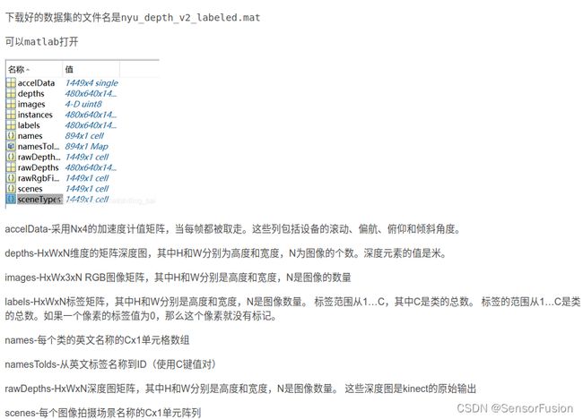
nyuV2 深度值 10m内,KinectV2采用tof技术,测距一般5m内,数据集可能手工标注了或者slam获取
讀取數據:
# Download the preprocessed NYU Depth V2 and/or KITTI Odometry dataset in HDF5 formats, and place them under the data folder. The downloading process might take an hour or so. The NYU dataset requires 32G of storage space, and KITTI requires 81G.
 mkdir data; cd data
 wget http://datasets.lids.mit.edu/sparse-to-dense/data/nyudepthv2.tar.gz
 tar -xvf nyudepthv2.tar.gz && rm -f nyudepthv2.tar.gz
 wget http://datasets.lids.mit.edu/sparse-to-dense/data/kitti.tar.gz
 tar -xvf kitti.tar.gz && rm -f kitti.tar.gz
 cd ..
import numpy as np
import matplotlib.pyplot as plt
import scipy.io as sio
import h5py
import os
f=h5py.File("nyu_depth_v2_labeled.mat")
images=f["images"]
images=np.array(images)

path_converted='./nyu_images'
if not os.path.isdir(path_converted):
    os.makedirs(path_converted)

from PIL import Image
images_number=[]
for i in range(len(images)):
    images_number.append(images[i])
    a=np.array(images_number[i])
    r = Image.fromarray(a[0]).convert('L')
    g = Image.fromarray(a[1]).convert('L')
    b = Image.fromarray(a[2]).convert('L')
    img = Image.merge("RGB", (r, g, b))
    img = img.transpose(Image.ROTATE_270)
    iconpath='./nyu_images/'+str(i)+'.jpg'
    img.save(iconpath,optimize=True)
讀取深度圖
import numpy as np
import h5py
import os
from PIL import Image

f=h5py.File("nyu_depth_v2_labeled.mat")
depths=f["depths"]
depths=np.array(depths)

path_converted='./nyu_depths/'
if not os.path.isdir(path_converted):
    os.makedirs(path_converted)

max = depths.max()
print(depths.shape)
print(depths.max())
print(depths.min())

depths = depths / max * 255
depths = depths.transpose((0,2,1))

print(depths.max())
print(depths.min())

for i in range(len(depths)):
    print(str(i) + '.png')
    depths_img= Image.fromarray(np.uint8(depths[i]))
    depths_img = depths_img.transpose(Image.FLIP_LEFT_RIGHT)
    iconpath=path_converted + str(i)+'.png'
    depths_img.save(iconpath, 'PNG', optimize=True)

#同样方法可以提取rawdepth 对比查看深度图修复效果
深度图转点云
/*
* @Author: Jiang Chang
* @Date: 2022-10-24 17:53:52
* @LastEditors: Zeng YuTing
* @LastEditTime: 2022-10-24 17:55:41
* @FilePath: /66_hand_point_rgb_calibration/read_iphone_depth/tof_depth_pcd/main.cpp
* @Description:
*
* Copyright (c) 2022, All Rights Reserved.
*/
#include (m)[n * 3];
// p.g = rgb.ptr(m)[n * 3 + 1];
// p.r = rgb.ptr(m)[n * 3 + 2];
// 把p加入到点云中
cloud->points.push_back(p);
}
// 设置并保存点云
cloud->height = 1;
cloud->width = cloud->points.size();
cout << "point cloud size = " << cloud->points.size() << endl;
cloud->is_dense = false;
pcl::io::savePCDFile("../../iphone_depth_point.pcd", *cloud);
// 清除数据并退出
cloud->points.clear();
cout << "Point cloud saved." << endl;
}
import csv
import numpy as np
import sys
#sys.path.remove('/opt/ros/kinetic/lib/python2.7/dist-packages')
import cv2
import numpy as np
import pcl
#from pcl import PointCloud


depth_cam_matrix = np.array([[1537.1, 0,  977.48],
                                 [0,   1538.3,   505.62],
                                 [0,   0,    1]])


def depth2xyz(depth_map,depth_cam_matrix,flatten=False,depth_scale=1.):
    fx,fy = depth_cam_matrix[0,0],depth_cam_matrix[1,1]
    cx,cy = depth_cam_matrix[0,2],depth_cam_matrix[1,2]
    h,w=np.mgrid[0:depth_map.shape[0],0:depth_map.shape[1]]
    print ('h',h)
    print ('w',w)
    depth_scale=1
    z=depth_map/depth_scale
    x=(w-cx)*z/fx
    y=(h-cy)*z/fy
    print ('len(x):',len(x))
    print ('y:',y)
    print ('z:',z)
    xyz=np.dstack((x,y,z))
    print ('xyz:',xyz)
    #if flatten==False
    #else np.dstack((x,y,z)).reshape(-1,3)
    #xyz=cv2.rgbd.depthTo3d(depth_map,depth_cam_matrix)
    return xyz

def read_iphone(csv_path):

    pixel_data = np.zeros([256,192]);
    print(pixel_data.shape)
    with open(csv_path,"r") as csvfile:
        reader = csv.reader(csvfile)
        for line in reader:
            print(line)
            pixel_data[int(line[0]), int(line[1])] = line[2]
    print(pixel_data)
    pixel_data = cv2.flip(pixel_data, 1)
    cv2.imwrite('pixel_data.png', pixel_data/10*255)
    return pixel_data

def save_pcd(result_cloud,save_pcd_name):
    [rows, cols] = result_cloud.shape
    points_count = rows
    output = open(save_pcd_name ,'w+')
    print('save pcd = ', save_pcd_name)
    list = ['# .PCD v.5 - Point Cloud Data file format\n','VERSION .5\n','FIELDS x y z\n','SIZE 3 3 3\n','TYPE F F F\n','COUNT 1 1 1\n']
    output.writelines(list)
    output.write('WIDTH ')
    output.write(str(points_count))
    output.write('\nHEIGHT')
    output.write(str(1))
    output.write('\nPOINTS ')
    output.write(str(points_count))
    output.write('\nDATA ascii\n')
    for i in range(rows):
        output.write(str(result_cloud[i][0]) + '\t' + str(result_cloud[i][1]) + '\t' + str(result_cloud[i][2]) +'\n')
    output.close()


if __name__ == '__main__':
    csv_path = "ipad_x_y_depth_113535.373775333.csv"
    #method 1:
    pixel_data = read_iphone(csv_path)
    cv2.imwrite('pixel_data.png', pixel_data/10*255)
    #depth2xyz
    pixel_data = pixel_data/10*255
    pc_xyz = depth2xyz(pixel_data, depth_cam_matrix)
    print('pc_xyz',pc_xyz)
    print(pc_xyz.shape)
    pc_xyz = pc_xyz.reshape(-1,3)
    print(pc_xyz.shape)
    #method 2:
    #point_cloud = pcl.PointCloud(pc_xyz.astype(np.float32))
    #pcl.saves("pc_xyz.pcd",point_cloud)
    #cloud1 = pcl.PointCloud.PointXYZ.from_array(pc_xyz)
    #cloud = pcl.load_XYZI("/home/ting/11_tof_livox/2022-09-30-12-49-39.pcd")
    #visual = pcl.visualization.CloudViewing()
    save_pcd_name = "result.pcd"
    save_pcd(pc_xyz,save_pcd_name)
算法:
17年paper
https://github.com/fangchangma/sparse-to-dense.pytorch
稀疏的点 与 稠密rgb像素 → 稠密的点
二、 双目
双目标定思路:
1:单组数据:

单目标定的过程,在从单应矩阵是分解内参时,可以求得相应的旋转矩阵 和平移向量 。
2: 多组数据获取双目外参
当然,每组的棋盘格图像会得到不同的RT值,之后需要通过LM算法找到一个重投影误差最小的解
如果需要双目系统
还需要立体矫正
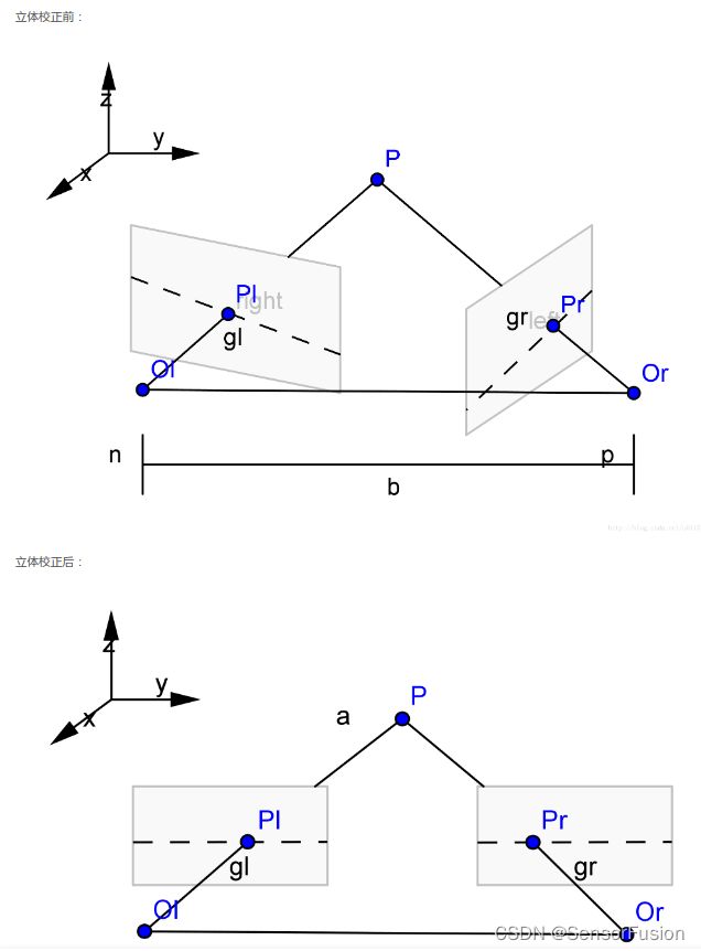
在介绍立体校正的具体方法之前,让我们来看一下,为什么要进行立体校正?
双目摄像机系统主要的任务就是测距,而视差求距离公式是在双目系统处于理想情况下推导的,但是在现实的双目立体视觉系统中,是不存在完全的共面行对准的两个摄像机图像平面的。所以我们要进行立体校正。
立体校正的目的就是,把实际中非共面行对准的两幅图像,校正成共面行对准。(共面行对准:两摄像机图像平面在同一平面上,且同一点投影到两个摄像机图像平面时,应该在两个像素坐标系的同一行),将实际的双目系统校正为理想的双目系统。
理想双目系统:两摄像机图像平面平行,光轴和图像平面垂直,极点处于无线远处,此时点(x0,y0)对应的级线就是y=y0
立体矫正看如下文章:
https://www.zhihu.com/question/486136535/answer/2631686893
三、 3D 相机
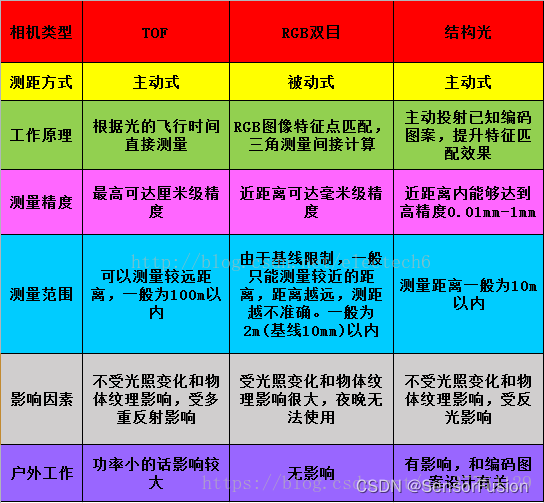
TOF深度相机属于固态激光雷达TOF测距原理在3D方向的一个应用。与其他激光雷达应用不同的是,3D(深度)TOF相机属于无扫描器件,其成像不是像传统激光雷达逐点扫描的方式,而是采用类似照相机的工作模式,一次性实现全局成像来完成探测和成像,每个像素点都可记录光子飞行的时间。由于物体具有三维空间属性,照射到物体不同部位的光具有不同的飞行时间,因此输出具有深度信息的“三维”图像。
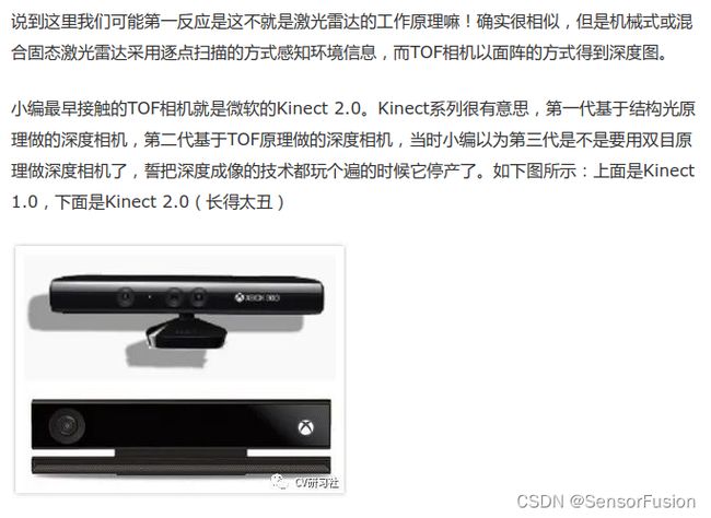
TOF方案深度图分辨率很难提高,一般都达不到VGA(640x480)分辨率。比如Kinect2的TOF方案深度图分辨率只有512x424。而Google和联想合作的PHAB2手机的后置TOF深度相机分辨率只有224x171。TOF方案受物理器件的限制,分辨率很难做到接近VGA的,即使做到,也会和功耗呈指数倍增长。


四、d-TOF
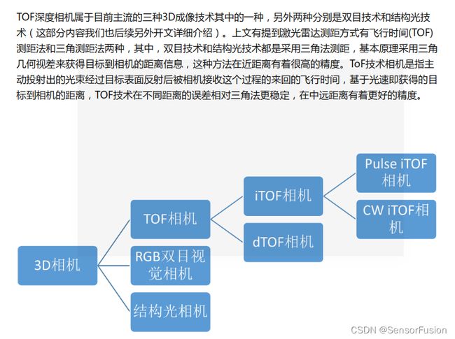
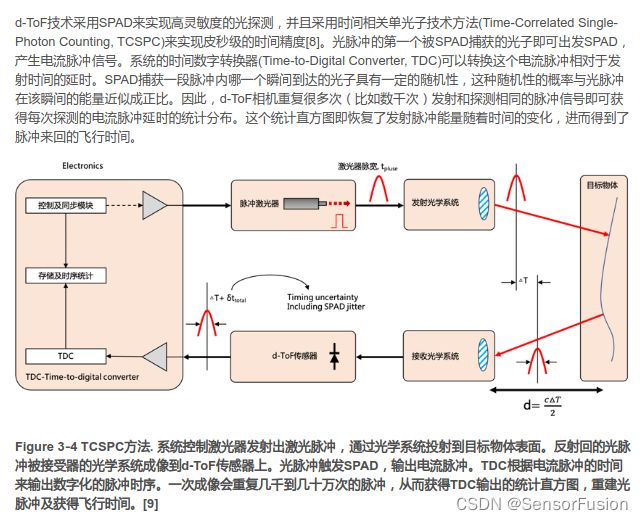
dTOF-直接测量飞行时间,即直接测量光脉冲发射与接收的时间间隔,与iTOF相比,dTOF在远距离及抗干扰方面会有明显优势,但其工艺复杂,集成难度较高;
五、 i-TOF
iTOF-间接测量飞行时间,大部分间接测量方案都是采用了一种测相位偏移的方法,即发射正弦波/方波与接收正弦波/方波之间相位差,通过传感器在不同时间窗口采集到能量值的比例关系,解析出信号相位,间接测量发射信号和接收信号的时间差,进而得到深度。与dTOF相比,i-ToF不仅在成本方面有优势,而且其工艺和产业链已趋于成熟,已大刀阔斧地加入到了3D视觉行业市场份额的抢夺战中。下文也着重讲解一下已经在消费电子领域、机器人领域、安防监控、轨道交通领域以及无人驾驶和工业自动化领域实现较多应用的两种iTOF相机技术。
iTOF又分为Pulse iTOF(脉冲调制)和Continuous Wave iTOF(CW iTOF,连续波调制),前者解析脉冲信号相位来解析深度,后者解析正弦信号相位解析深度。
相比CW iToF连续波调试方式,Pulse iToF 解算深度更简单、计算量更低,对于平台后端处理能力要求也相应更低。然而,Pulse iToF 的精度取决于发光次数,发光次数越多,精度越高,但同时也会带来功耗的增加。即使在相同平均功耗的情况下,Pulse iToF不仅精度弱于CW iToF,而且对于背景噪声更加敏感。
维感科技在推出基于Pulse iTOF的DCAM550/DCAM560C工业相机系列后,将于2022年6月份推出基于SONY CW iTOF的DS77系列,较DCAM550/DCAM560C两个系列产品,DS77系列在精度、稳定性、抗干扰方面,都会有更值得期待的表现。
六、 结构光
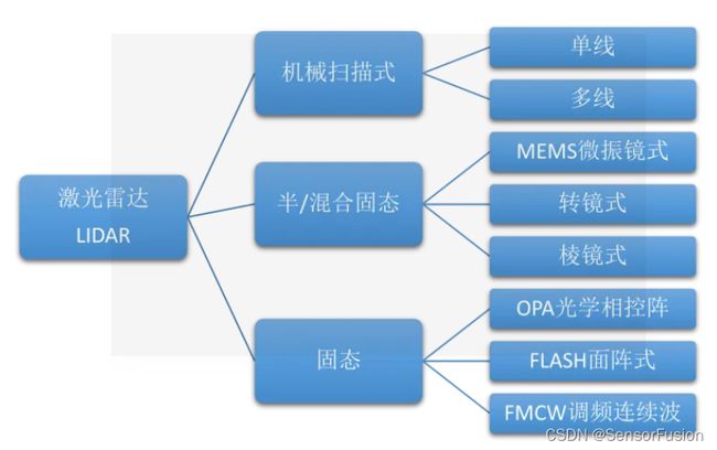
七、 激光雷达
-LIDAR(Light Detection and Ranging)
原理与雷达相同,只是发射波的形式是激光,即通过发射激光来测量周围事物的距离。
