机器人仿真搭建(以ABB为例)
说明:本次内容基于上两篇文章《基于C#的机器人仿真平台和机器人运动学算法实现》和《六轴机器人轨迹规划(直线轨迹规划,弧线轨迹规划)——C#实现+ABB为例(规划直接下发离线程序运动)》进行模型优化和相关算法和结构Code进行优化,并将其整合。
一,模型优化
1.鉴于上篇文章中模型不够好看和模型细节不到位的问题在本次修改中做出了相应的修改
老规矩,先上图:
Program Interface:


Robot Model1 —— IRB2600

Robot Model2 —— IRB6700
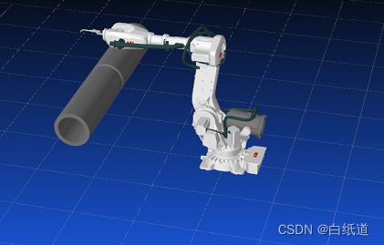
PS:在模型优化中对新模型的各连杆机构进行不同程度重构,最终将拼接起来的机器人展示在界面中并且可以达到模型各连杆之间模型不冲突,可以按要求做到连贯连续的动作。
GIF动画:
可以看到,模型在运动过程中没有出现各连杆错位或者模型错误的情况。
Reference Code(Not all of it but core code)
#if IRB6700
        private const string MODEL_PATH1 = "IRB6700-MH3_245-300_IRC5_rev01_BASE_CAD.stl";
        private const string MODEL_PATH2 = "IRB6700-MH3_245-300_IRC5_rev02_LINK01_CAD.stl";
        private const string MODEL_PATH3 = "IRB6700-MH3_245-300_IRC5_rev00_LINK02_CAD.stl";
        private const string MODEL_PATH4 = "IRB6700-MH3_245-300_IRC5_rev02_LINK03_CAD.stl";
        private const string MODEL_PATH5 = "IRB6700-MH3_245-300_IRC5_rev01_LINK04_CAD.stl";
        private const string MODEL_PATH6 = "IRB6700-MH3_245-300_IRC5_rev01_LINK05_CAD.stl";
        private const string MODEL_PATH7 = "IRB6700-MH3_245-300_IRC5_rev01_LINK06_CAD.stl";
        private const string MODEL_PATH8 = "IRB6700-MH3_245-300_IRC5_rev00_LOGO1_CAD.stl";
        private const string MODEL_PATH9 = "IRB6700-MH3_245-300_IRC5_rev00_LOGO2_CAD.stl";
        private const string MODEL_PATH10 = "IRB6700-MH3_245-300_IRC5_rev00_LOGO3_CAD.stl";
        private const string MODEL_PATH11 = "IRB6700-MH3_245-300_IRC5_rev00_CYLINDER_CAD.stl";
        private const string MODEL_PATH12 = "IRB6700-MH3_245-300_IRC5_rev02_LINK01_CABLE.stl";
        private const string MODEL_PATH13 = "IRB6700-MH3_245-300_IRC5_rev02_LINK01m_CABLE.stl";
        private const string MODEL_PATH14 = "IRB6700-MH3_245-300_IRC5_rev00_LINK02_CABLE.stl";
        private const string MODEL_PATH15 = "IRB6700-MH3_245-300_IRC5_rev00_LINK02m_CABLE.stl";
        private const string MODEL_PATH16 = "IRB6700-MH3_245-300_IRC5_rev00_LINK03a_CABLE.stl";
        private const string MODEL_PATH17 = "IRB6700-MH3_245-300_IRC5_rev00_LINK03b_CABLE.stl";
        private const string MODEL_PATH18 = "IRB6700-MH3_245-300_IRC5_rev02_LINK03m_CABLE.stl";
        private const string MODEL_PATH19 = "IRB6700-MH3_245-300_IRC5_rev01_LINK04_CABLE.stl";
        private const string MODEL_PATH20 = "hanqiang.stl";
        private const string GUAN_DAO = "guandao1.stl";
#else
        private const string MODEL_PATH1 = "IRB2600_12_165_base_CAD_01.step.STL";
        private const string MODEL_PATH2 = "IRB2600_12_165_link1_CAD_01.STL";
        private const string MODEL_PATH3 = "IRB2600_12_165_link2_CAD_01.STL";
        private const string MODEL_PATH4 = "IRB2600_12_165_link3_CAD_01.STL";
        private const string MODEL_PATH5 = "IRB2600_12_165_link4_CAD_02.STL";
        private const string MODEL_PATH6 = "IRB2600_12_165_link5_CAD_02.STL";
        private const string MODEL_PATH7 = "IRB2600_12_165_link6_CAD_01.STL";
        private const string MODEL_PATH8 = "IRB6700-MH3_245-300_IRC5_rev00_LOGO1_CAD.stl";
        private const string MODEL_PATH9 = "IRB6700-MH3_245-300_IRC5_rev00_LOGO2_CAD.stl";
        private const string MODEL_PATH10 = "IRB6700-MH3_245-300_IRC5_rev00_LOGO3_CAD.stl";
        private const string MODEL_PATH11 = "IRB2600_12_165_cables_link1a_CAD_00.STL";
        private const string MODEL_PATH12 = "IRB2600_12_165_cables_link1b_CAD_00.STL";
        private const string MODEL_PATH13 = "IRB2600_12_165_cables_link2_CAD_00.STL";
        private const string MODEL_PATH14 = "IRB2600_12_165_cables_link3_CAD_00.STL";
        private const string MODEL_PATH20 = "hanqiang2.stl";
        private const string GUAN_DAO = "guandao2.stl";
        private const string ZHENGTI = "zhengti.stl";
#endif


 public UserControl1()
        {
            InitializeComponent();
#if IRB6700
            RoboticArm.Content = Initialize_Environment(MODEL_PATH1, MODEL_PATH2, MODEL_PATH3, MODEL_PATH4, MODEL_PATH5, MODEL_PATH6, MODEL_PATH7, MODEL_PATH8, MODEL_PATH9, MODEL_PATH10, MODEL_PATH11,
                MODEL_PATH12, MODEL_PATH13, MODEL_PATH14, MODEL_PATH15, MODEL_PATH16, MODEL_PATH17, MODEL_PATH18, MODEL_PATH19, MODEL_PATH20);
#else
            RoboticArm.Content = Initialize_Environment(MODEL_PATH1, MODEL_PATH2, MODEL_PATH3, MODEL_PATH4, MODEL_PATH5, MODEL_PATH6, MODEL_PATH7, MODEL_PATH8, MODEL_PATH9, MODEL_PATH10, MODEL_PATH11,
                MODEL_PATH12, MODEL_PATH13, MODEL_PATH14);
#endif
            //显示模型的函数\
            //Zhengti.Content = ZhengTi();
            hanqiang11.Content = Hanqiang();
            sanjiaoxing.Content = GUandao();
            viewPort3d.Children.Add(RoboticArm);//helixviewPort3d的name:viewPort3d;这句code的意思是将机械臂显示在helexviewport3d上
            viewPort3d.Children.Add(sanjiaoxing);
            viewPort3d.Children.Add(hanqiang11);
            //viewPort3d.Children.Add(Zhengti);
            viewPort3d.Camera.LookDirection = new Vector3D(500, -1000, -500);//初始视角

        }


 public void Refresh3D()
        {
            try
            {

                T = new TranslateTransform3D(0, 0, 0);
                F1.Children.Add(T);

                T= new TranslateTransform3D;

                R = new RotateTransform3D(new AxisAngleRotation3D(new Vector3D(0, 0, 1), g1), new Point3D());
                F2.Children.Add(T);
                F2.Children.Add(R);
                F2.Children.Add(F1);
                //T = new TranslateTransform3D(0, 0, 0);

                T = new TranslateTransform3D;
                R = new RotateTransform3D(new AxisAngleRotation3D(new Vector3D(0, 1, 0), g2), new Point3D());
                F3.Children.Add(T);
                F3.Children.Add(R);
                F3.Children.Add(F2);

                T = new TranslateTransform3D;
                R = new RotateTransform3D(new AxisAngleRotation3D(new Vector3D(0, 1, 0), g3), new Point3D());
                F4.Children.Add(T);
                F4.Children.Add(R);
                F4.Children.Add(F3);

                T = new TranslateTransform3D;
                R = new RotateTransform3D(new AxisAngleRotation3D(new Vector3D(1, 0, 0), g4), new Point3D());
                F5.Children.Add(T);
                F5.Children.Add(R);
                F5.Children.Add(F4);

                T = new TranslateTransform3D;
                R = new RotateTransform3D(new AxisAngleRotation3D(new Vector3D(0, 1, 0), g5), new Point3D());
                F6.Children.Add(T);
                F6.Children.Add(R);
                F6.Children.Add(F5);

                T = new TranslateTransform3D;
                R = new RotateTransform3D(new AxisAngleRotation3D(new Vector3D(1, 0, 0), g6), new Point3D());
                F7.Children.Add(T);
                F7.Children.Add(R);
                F7.Children.Add(F6);
                //T = new TranslateTransform3D;
                //R = new RotateTransform3D(new AxisAngleRotation3D(new Vector3D(1, 0, 0), g6), new Point3D());
                //F11.Children.Add(T);
                //F11.Children.Add(R);
                //F11.Children.Add(F7);
                //R = new RotateTransform3D(new AxisAngleRotation3D(new Vector3D(1, 0, 0), 0), new Point3D());
                //F11.Children.Add(T);
                //F11.Children.Add(R);
                //F11.Children.Add(F7);

                T = new TranslateTransform3D;
                R = new RotateTransform3D(new AxisAngleRotation3D(new Vector3D(0, 1, 0), -90), new Point3D());
                F8.Children.Add(T);
                F8.Children.Add(R);
                F8.Children.Add(F2);

                T = new TranslateTransform3D;
                R = new RotateTransform3D(new AxisAngleRotation3D(new Vector3D(0, 1, 0), 0), new Point3D());
                RotateTransform3D R1 = new RotateTransform3D(new AxisAngleRotation3D(new Vector3D(0, 0, 1), -90));
                F9.Children.Add(T);
                F9.Children.Add(R);
                F9.Children.Add(R1);
                F9.Children.Add(F5);

                //T = new TranslateTransform3D;
                R = new RotateTransform3D(new AxisAngleRotation3D(new Vector3D(0, 1, 0), 0), new Point3D());
                F10.Children.Add(T);
                F10.Children.Add(R);
                F10.Children.Add(F9);
            }
            catch (Exception e)
            {
                //MessageBox.Show("refresh Exception Error:" + e.StackTrace);
            }
        }
二,代码结构处理和真实机器人联动功能
1.在本次创作中,首次添加了真实仿真模块,和算法模块仿真不同,该仿真模块基于现实机器人的动作进行仿真,摆脱了机器人厂家自带的仿真平台,可以拓展各个型号的机器人
上图,下图展示了获取真实机器人的位置和姿态信息,并且做出相应动作
Robotstudio中2600位姿如图:

仿真程序中2600位姿如图:

ps:焊枪不同,所以视觉看起来位置有误差,其实位姿和Robotstudio中机器人完全相同
GIF图(通过示教器控制仿真程序中机器人)
相关代码在之前文章中有类似,在此不做重复说明!
三,同样可以根据点位规划离线程序,具有更强的可视化性
如图:


Fi:算法仿真模块可以看上篇文章《基于C#的机器人仿真平台和机器人运动学算法实现》中的相关内容,本片文章不再做阐述,谢谢大家,后续会继续推出更有趣的机器人内容!!!