基于RSS和TOA两种方法的无线传感器网络定位测量算法matlab仿真
up目录
一、理论基础
二、核心程序
三、测试结果
一、理论基础
无线传感器网络(Wireless Sensor Networks, WSN)是一种分布式传感网络,它的末梢是可以感知和检查外部世界的传感器。WSN中的传感器通过无线方式通信,因此网络设置灵活,设备位置可以随时更改,还可以跟互联网进行有线或无线方式的连接。无线传感器网络主要由三大部分组成,包括节点、传感网络和用户这3部分。其中,节点一般是通过一定方式将节点覆盖在一定的范围,整个范围按照一定要求能够满足监测的范围;传感网络是最主要的部分,它是将所有的节点信息通过固定的渠道进行收集,然后对这些节点信息进行一定的分析计算,将分析后的结果汇总到一个基站,最后通过卫星通信传输到指定的用户端,从而实现无线传感的要求。
基于距离的定位算法通过测量不同节点到目标信号间的距离或角度信息,利用最大似然估计定位法、三角测量定位法、三边测量定位法估计未知目标节点的位置。
常用定位算法:
- 到达角度算法(AOA)
- 达到时间算法(TOA)
- 到达时间差算法(TDOA)
- 接收信号能量算法(RSSI)
无线传感器网络目标定位方式主要如下:
(1)主动模式
基于距离的定位:测量节点间距离或方位时采用的方法有:到达时间T0A(TOA,Time Of Arrive),到达时间差TDOA,到达角度AOA,接收信号强度指示RSSI。目前常选择RSSI来进行跟踪定位。基于距离的定位方法虽然能够达到很好的精度,但共同缺点都是需要节点间的严格同步,且能量消耗大。
(2)被动模式
与距离无关的定位中,一种方法是对节点到目标间的距离进行估计,然后通过三边测量法或极大似然估计法进行定位。还有一种方法是将包含目标的区域中心或离目标最近的节点位置作为目标位置。
(3)基于声波衰减模型的定位
这种方法需要根据经验测量获得比较接近实际的模型,因此在定位误差上有待提高。
无线传感器网络的许多应用要求节点知道自身的位置信息,才能向用户提供有用的检测服务。没有节点位置信息的监测数据在很多场合下是没有意义的。比如,对于森林火灾检测、天然气管道监测等应用,当有事件发生时,人们关心的一个首要问题就是事件发生在哪里,此时如果只知道发生了火灾却不知道火灾具体的发生地点,这种监测没有任何实质的意义,因此节点的位置信息对于很多场合是至关重要的。
RSS测量模型制定如下。假设源发射功率为Pt ,在没有干扰的情况下,第i个传感器接收到的平均功率为Pi,模型为:
在自由空间中,没有任何障碍物,信号从发射源向四面八方呈球面形状发射出去,各个方向上没有任何区别,因此信号的功率和距离的平方呈反比:(P propto frac{1}{d^2})。RSS就是功率,但是衰减的单位一般用dB来表示,那么就很容易理解RSS与距离的关系了,RSS衰减与距离的对数呈正比,假设已知一个参考距离(d_0)以及这个距离上的RSS为(RSS(d_0)),那么,(RSS(d) = RSS(d_0) - 10nlog(frac{d}{d_0}))。自由空间中(n=2),这就是最常见的对数距离损耗模型(针对室内的传播模型还有分隔损耗、楼层间分隔损耗、Ericsson多重断点模型等)。下图中的黑线是一组在走廊中测量的实际数据,红线是对数距离损耗模型的拟合结果,可以看出模型可以反映总体趋势,但和真实室内环境下的情况还是有较大区别,注意黑线的波动不是因为噪声,而是实际的信号传播环境造成的。走廊这种场景算是比较简单的,如果在其他一下更复杂的场景下,有更多的信号遮挡、反射等因素存在,RSS不仅和距离位置有关,还和周围的各种障碍物有关系,因此在更复杂一点的场景下,可以用射线跟踪技术来分析。
TOA 定位方法,主要是根据测量接收信号在基站和移动台之间的到达时间,然后转换为距离,从而进行定位。该方法至少需要三个基站,才能计算目标的位置,其定位示意图如图所示。 当基站能同时获得 TOA 和 AOA 信息时,通常联合上述公式,采用 TOA/AOA 混合定位方法,令
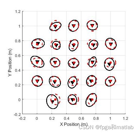
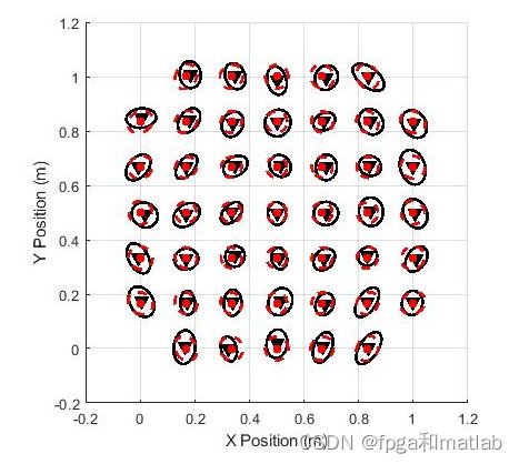
同理利用 LS 算法求解,得到移动台的位置。ToA方法计算信号从UD到ANs所需要的时间,UD在一个以AN为中心的圆周上,通过ToA测量的到达时间可以计算出圆半径d。因此,为了检测UD的确切位置,至少需要3个ANs。在本例中,UD的估计位置仅在三个圆的相交区域(如果存在的话)内,如图所示。然后,通过LS或加权最小二乘法(WLS)等任何滤波技术都可以很容易地得到实际的估计位置。
二、核心程序
% Basic simulation parameters
roomSize        = [1,1];       % Room size, meters
gridSize        = 3;           % How many sensors per side
refDevices      = 4;           % How many references (must be same length as actualRefLocs)
trials          = 30;          % How many indep trials to run
measMethod      = 'R';         % Use 'R' for RSS, 'T' for TOA
totalDevices    = gridSize^2;
blindDevices    = totalDevices - refDevices;
blindCoords     = 2*blindDevices;
actualRefLocs   = [0,0; 0,1; 1,1; 1,0];
linearRefLocs   = [actualRefLocs(:,1)', actualRefLocs(:,2)'];

% Optimization parameters
ftol  = 0.00001;
if measMethod == 'R',
    func  = 'calcError';       % Use for RSS
    dfunc = 'calcDError';      % Use for RSS
else
    func  = 'calcErrorTOA';    % Use for TOA
    dfunc = 'calcDErrorTOA';   % Use for TOA
end


%| 1. Set up the blindfolded device locations
delta    = 1/(gridSize-1);
coords   = 0:delta:1;
xMatrix  = ones(gridSize,1)*coords;
yMatrix  = xMatrix';
xBlind   = [xMatrix(2:gridSize-1), ...
        xMatrix(gridSize+1:totalDevices-gridSize), ...
        xMatrix(totalDevices-gridSize+2:totalDevices-1)];
yBlind   = [yMatrix(2:gridSize-1), ...
        yMatrix(gridSize+1:totalDevices-gridSize), ...
        yMatrix(totalDevices-gridSize+2:totalDevices-1)];
actualBlindLocs = [xBlind', yBlind'];
actualAllLocs   = [actualRefLocs; actualBlindLocs];
xActual         = actualAllLocs(:,1)';
yActual         = actualAllLocs(:,2)';
actualDist      = L2_distance(actualAllLocs', actualAllLocs',0);

%| 2.  Define the channel model
if measMethod == 'R';
    sigmaOverN = 1.7;

    C = 1;
else
    sigma_d = 0.2;                               % Use for TOA
end

for trial = 1:trials,


    if measMethod == 'R';

        dhat  = actualDist.*10.^(sigmaOverN/10 .*symrandn(totalDevices))./C;
    else

        dhat  = actualDist + sigma_d .* symrandn(totalDevices);
    end

    blindLocs0 = [xBlind, yBlind]; % Use the true coordinates (unrealistic but best case)

    funcEvals = 0;  dfuncEvals = 0;
    [coordsMLE, iter, errorMin] = frprmn(blindLocs0, ftol, func, dfunc, 0);
    disp(sprintf('%d: Function / Deriv. evals: %d / %d.', trial, funcEvals, dfuncEvals));

    coordEsts(trial, 1:blindCoords) = coordsMLE;
end % for trial

estMean = mean(coordEsts);
estCov  = cov(coordEsts);
estVars = diag(estCov);
estStds = sqrt(estVars);
locVars = estVars(1:blindDevices) + estVars((blindDevices+1):(2*blindDevices));
locStd  = sqrt(locVars);

toc  % show time of execution

% Plot the location estimates for sensors, one at a time.
if 0,
    figure
    for i=1:blindDevices,
        clf
        plot(coordEsts(:,i), coordEsts(:,blindDevices+i),'.', ...
            estMean(i), estMean(blindDevices+i), 'ro')
        hold on
        set(gca,'xlim',[-0.2 1.2])
        set(gca,'ylim',[-0.2 1.2])
%         set(gca,'FontSize',20)
%         set(gca,'DataAspectRatio',[1 1 1])
        xlabel('X Position (m)')
        ylabel('Y Position (m)')
%         set(gca,'xTick',0:0.25:1)
%         set(gca,'yTick',0:0.25:1)
        grid;
        pause;
    end
end
function [dError] = calcDErrorTOA(guessBlindLocs)

global refDevices;    % number of reference devices
global blindDevices;  % number of blind devices
global totalDevices;  % the total number of devices
global linearRefLocs; % actual coordinates of the reference devices
global dhat;          % estimated distance between devices based on the measured received power.
global dfuncEvals;    % counter for number of function evaluations.
dfuncEvals = dfuncEvals + 1;
TINY = 1e-8;

%| 1.  Use these for the calculation of the relative location error term
x = [linearRefLocs(1:refDevices), guessBlindLocs(1:blindDevices)];
y = [linearRefLocs(refDevices+1:2*refDevices), ...
     guessBlindLocs(blindDevices+1:2*blindDevices)];

for k = (refDevices+1) : totalDevices,
   l = [1:k-1];
   modelDist       = max(TINY, sqrt(((x(k)-x(l)).^2 + (y(k)-y(l)).^2)));
   commonTerm(k,l) = 2.*(1 - dhat(k,l)./modelDist);
end
commonTerm(:,totalDevices) = zeros(totalDevices,1);


dFdx = zeros(1,totalDevices);
dFdy = zeros(1,totalDevices);
% row-wise error slopes
for k = (refDevices+1) : totalDevices,
    others   = 1:k-1;
    dFdx(k)  = sum(commonTerm(k,others).*(x(k)-x(others)));
    dFdy(k)  = sum(commonTerm(k,others).*(y(k)-y(others)));
end
% column-wise error slopes
for k = refDevices+1 : (totalDevices-1),
    others   = (k+1):totalDevices;
    dFdx(k)  = dFdx(k) + sum(commonTerm(others, k)'.*(x(k)-x(others)));
    dFdy(k)  = dFdy(k) + sum(commonTerm(others, k)'.*(y(k)-y(others)));
end

%| 3. Return the error in a vector.
dError = [dFdx((refDevices+1) : totalDevices), dFdy((refDevices+1) : totalDevices)];
三、测试结果
up00015


