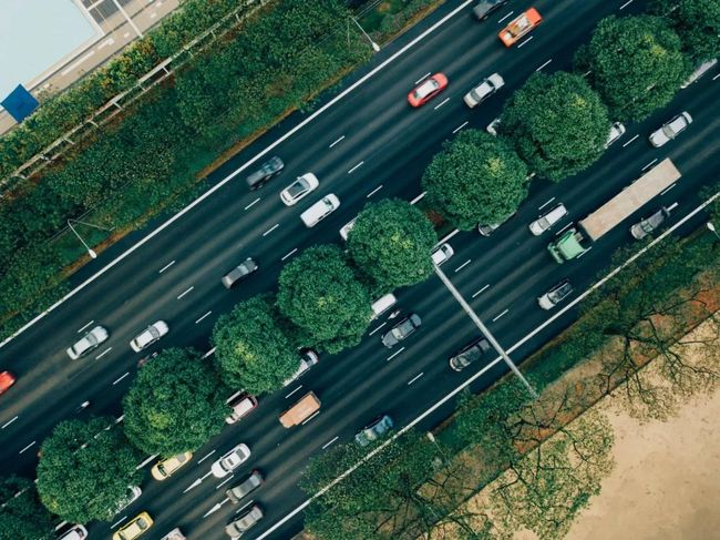
自动驾驶:基于PCL的激光雷达感知
介绍
自动驾驶是现代技术中一个相对较新且非常迷人的领域。在2004年的DARPA Grand Challenge期间公开展示,并在2007年转向更具挑战性的城市环境,自那以后,工业界和学术界一直在追求自动驾驶。
这些应用程序在个人自动驾驶汽车、自动出租车、运输、送货等方面都有所不同,但这项技术还没有成熟。
自动驾驶陷入低谷的原因之一是,感知组件是一个非常复杂的问题。虽然大多数团队都采用基于激光雷达的感知方式,但仍有人试图通过相机来感知(Tesla 和 Wayve)。
依赖激光雷达的解决方案也可以分为两类:处理点云的传统计算机视觉算法和基于深度学习的方法。
神经网络有望以较高的平均精度解决感知问题,然而,如果我们想在最坏的情况下证明合理的准确性,这是不够的。
在本文中,我们将看一看在PCL(一个开源的点云库)的帮助下制作的自动驾驶堆栈。
首先,我们将坚持系统级的测试驱动开发(TDD),以确保在第一次现场部署之前对我们的整个代码进行彻底测试。
为此,我们需要一个数据集来运行代码。卡尔斯鲁厄理工学院(Karlsruhe Institute of Technology)和芝加哥丰田理工学院(Toyota Technology Institute)2012年的经典数据集Kitti将非常适合这一目的。这是首批收集的大规模高质量数据集之一,可作为自动驾驶领域计算机视觉算法的基准。
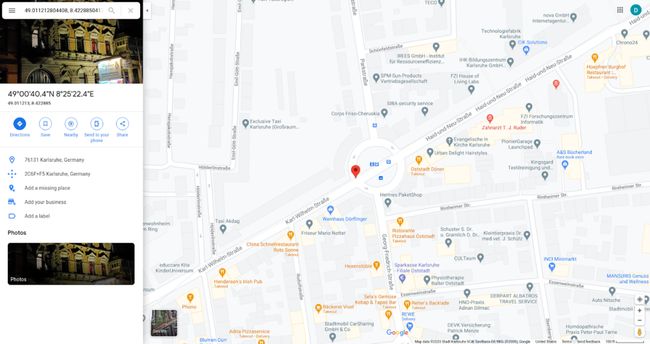
Kitti跟踪由21个同步PNG图像序列、Velodyne激光雷达扫描和来自RT3003 GPS-IMU模块的NMEA记录组成。
数据集的一个重要特征是传感器之间的彻底相互校准,包括矩阵“Tr_imu_velo”,它是从GPS-imu坐标到Velodyne激光雷达坐标的转换。
感知管道的架构如下所示。

让我们分别讨论每一个组件,深入挖掘他们的C++实现。
点云抽取
为什么我们可能需要从深度传感器(可能是一个或几个激光雷达)中抽取点云?
自动驾驶软件最重要的要求是满足实时操作约束。
第一个要求是处理管道要跟上激光雷达扫描采样的速率。在现实生活中,扫描速度可能从10到25次/秒不等,这导致最大延迟为100毫秒到40毫秒不等。如果某些操作导致延迟超过100 ms(对于每秒10次扫描的速度),要么会发生帧丢失,要么管道的总延迟将开始任意增长。这里的解决方案之一是丢掉一些点,而不是丢失整个帧。这将逐渐降低准确性指标(召回率和精度),并保持管道实时运行。
第二个要求是系统的总体延迟或反应时间。同样,总延迟应该被限制在至少100或200毫秒。对于自动驾驶来说,500ms甚至1秒的反应时间是不可接受的。因此,在算法设计开始时,首先采用抽取的方法处理少量的点是有意义的。
抽取的标准选项包括:
有规律的
(伪)随机
格栅下采样
常规下采样速度很快,但可能会导致点云上的锯齿模式。随机或伪随机下采样也很快,但可能会导致不可预测的小对象完全消失。像PCL的pcl::VoxelGrid<>类一样的格栅下采样是智能和自适应的,但需要额外的计算和内存。
原始点云:
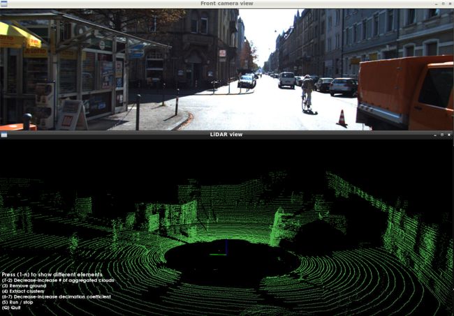
大量点云:
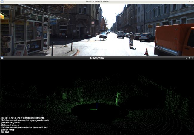
多扫描聚合
多扫描聚合是指当车相对于地面移动时,将多个历史激光雷达扫描记录到共同坐标系的过程。通用的坐标系统可以是局部导航框架或当前的激光雷达传感器坐标。我们将以后者为例。
这个阶段在理论上是可选的,但在实践中是非常重要的。问题是,后续的聚类阶段依赖于LiDAR点的密度,如果密度不够,可能会产生过聚类的影响。过聚类意味着任何对象(汽车、公共汽车、建筑墙等)都可以被分割成几个部分。
就其本身而言,这可能不是一个检测障碍的问题,然而,对于感知-跟踪-聚类的下游模块来说,这是一个实质性的挑战。跟踪器可能会不准确地关联对象的各个部分,这最终导致车辆突然刹车。我们绝对不希望聚类中的小错误在下游组件中造成雪崩式的错误。
多次连续扫描(5到10次)的聚合成比例地增加了落在每个物体上的激光雷达点的密度,并促进了精确的聚类。汽车运动的一个很好的特点是,汽车能够从不同的视角观察同一物体,激光雷达扫描模式覆盖物体的不同部分。
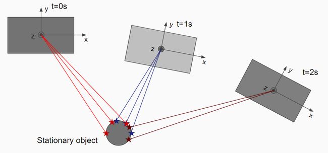
让我们看看执行聚合的代码。
第一阶段是保留一个限制长度的队列,其中包含历史点云以及后续扫描仪的姿势转换。请注意,我们如何使用从RT3003 GPS-IMU模块获得的平移速度[Vx,Vy]和旋转速度Wz来构造姿势变换。
// We accumulate the incoming scans along with their localization metadata
// into a deque to perform subsequent aggregation.
{
   Transform3f next_veh_pose_vs_curr = Transform3f::Identity();
   if (gpsimu_ptr)
   {
       float frame_interval_sec = 0.1f;

       // First, we need to calculate yaw change given the yaw rate
       // (angular speed over Z axis) and the time inteval between frames.
       float angle_z = gpsimu_ptr->wz * frame_interval_sec;
       auto rot = Eigen::AngleAxisf(angle_z, Eigen::Vector3f::UnitZ());
       next_veh_pose_vs_curr.rotate(rot);
       // Second, we need a translation transform to the next frame
       // given the speed of the ego-vehicle and the frame interval.
       next_veh_pose_vs_curr.translate(Eigen::Vector3f(
           gpsimu_ptr->vf * frame_interval_sec,
           gpsimu_ptr->vl * frame_interval_sec,
           0.0f
       ));
   }

   // Since later we want to aggregate all scans into the coordinate
   // frame of the last scans, we need the inverse transform.
   auto curr_veh_pose_vs_next = next_veh_pose_vs_curr.inverse();

   // Put the resulting pair of the cloud and the transform into a queue.
   auto cloud_and_metadata = CloudAndMetadata{decimated_cloud_ptr, curr_veh_pose_vs_next};
   m_queue.push_back(cloud_and_metadata);
   while (m_queue.size() > m_params->m_num_clouds)
   {
       m_queue.pop_front();
   }
}
在第二阶段,我们从最新的扫描时间向后遍历队列,进行聚合,并将聚合转换应用到每个历史帧。
使用这种方法,计算成本为O(N*D),其中N是点的数量,D是历史的深度(扫描的数量)。
// We accumulate the transforms starting from the latest back in time and
// transform each historical point cloud into the coordinates of the current frame.
auto aggregated_cloud_ptr = std::make_shared >();
Eigen::Matrix4f aggragated_transform = Eigen::Matrix4f::Identity();
for (int i = m_queue.size()-1; i >= 0; i--)
{
   const auto& cloud_and_metadata = m_queue[i];
   const auto& cloud_ptr = cloud_and_metadata.cloud_ptr;
   const auto& trans = cloud_and_metadata.transform_to_next;
   pcl::PointCloud::Ptr transformed_cloud_ptr;
   if (i != m_queue.size()-1)
   {
       aggragated_transform *= trans.matrix();
       transformed_cloud_ptr = std::make_shared >();
       pcl::transformPointCloud(*cloud_ptr, *transformed_cloud_ptr, aggragated_transform);
   }
   else
   {
       // For the current scan no need to transform
       transformed_cloud_ptr = cloud_ptr;
   }

   // Concatenate the transformed point cloud into the aggregate cloud
   *aggregated_cloud_ptr += *transformed_cloud_ptr;
}
聚合后,如果移动的物体看起来有点模糊,点云会显得有些模糊。可以在聚类阶段进一步解决。在这个阶段,我们需要的是一个更密集的点云,它可以从多个帧中积累信息。
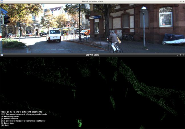
地面移除
感知堆栈的目的是提供有关动态对象和静止障碍物的信息。汽车应该在道路上行驶,通常路面不被视为障碍物。
因此,我们可以移除所有从路面反射的激光雷达点。要做到这一点,我们首先将地面检测为平面或曲面,并移除表面周围或下方约10厘米的所有点。有几种方法可以检测点云上的地面:
用Ransac探测平面
用Hough变换检测平面
基于Floodfill的非平面表面检测
让我们在EGIN和PCL库的帮助下,研究RANSAC的C++实现。
首先,让我们定义候选平面。我们将使用基点加法向量的形式。
// A plane is represented with a point on the plane (base_point)
// and a normal vector to the plane.
struct Plane
{
   Eigen::Vector3f base_point;
   Eigen::Vector3f normal;

   EIGEN_MAKE_ALIGNED_OPERATOR_NEW
};
然后,我们定义了一个辅助函数,它允许我们在点云转换为平面坐标后,在Z坐标上找到满足条件的所有点的索引。代码中的注释给出了实现的细节。
// This helper function finds indices of points that are considered inliers,
// given a plane description and a condition on distance from the plane.
std::vector find_inlier_indices(
   const pcl::PointCloud::Ptr& input_cloud_ptr,
   const Plane& plane,
   std::function condition_z_fn)
{
   typedef Eigen::Transform Transform3f;

   auto base_point = plane.base_point;
   auto normal = plane.normal;

   // Before rotation of the coordinate frame we need to relocate the point cloud to
   // the position of base_point of the plane.
   Transform3f world_to_ransac_base = Transform3f::Identity();
   world_to_ransac_base.translate(-base_point);
   auto ransac_base_cloud_ptr = std::make_shared >();
   pcl::transformPointCloud(*input_cloud_ptr, *ransac_base_cloud_ptr, world_to_ransac_base);

   // We are going to use a quaternion to determine the rotation transform
   // which is required to rotate a coordinate system that plane's normal
   // becomes aligned with Z coordinate axis.
   auto rotate_to_plane_quat = Eigen::Quaternionf::FromTwoVectors(
       normal,
       Eigen::Vector3f::UnitZ()
   ).normalized();

   // Now we can create a rotation transform and align the cloud that
   // the candidate plane matches XY plane.
   Transform3f ransac_base_to_ransac = Transform3f::Identity();
   ransac_base_to_ransac.rotate(rotate_to_plane_quat);
   auto aligned_cloud_ptr = std::make_shared >();
   pcl::transformPointCloud(*ransac_base_cloud_ptr, *aligned_cloud_ptr, ransac_base_to_ransac);

   // Once the point cloud is transformed into the plane coordinates,
   // We can apply a simple criterion on Z coordinate to find inliers.
   std::vector indices;
   for (size_t i_point = 0; i_point < aligned_cloud_ptr->size(); i_point++)
   {
       const auto& p = (*aligned_cloud_ptr)[i_point];
       if (condition_z_fn(p.z))
       {
           indices.push_back(i_point);
       }
   }
   return indices;
}
最后,主要的Ransac实现如下所示。第一步是基于Z坐标对点进行粗略过滤。此外,我们需要再次抽取点,因为我们不需要聚集云中的所有点来验证候选平面。这些操作可以一次完成。
接下来,我们开始迭代。在C++标准库的 std::mt19937伪随机生成器的帮助下,每次迭代采样3个随机点。对于每个三元组,我们计算平面并确保其法线指向上方。然后我们使用相同的辅助函数find_inlier_index来计算内点的数量。
迭代结束后,我们剩下的是最佳候选平面,我们最终使用它来复制点云中所有索引不存在于列表中的点的副本。请注意std::unordered_set<>的用法。它允许执行恒定时间O(1)搜索,而不是对std::vector<>进行的线性O(N)搜索。
// This function performs plane detection with RANSAC sampling of planes
// that lie on triplets of points randomly sampled from the cloud.
// Among all trials the plane that is picked is the one that has the highest
// number of inliers. Inlier points are then removed as belonging to the ground.
auto remove_ground_ransac(
   pcl::PointCloud::Ptr input_cloud_ptr)
{
   // Threshold for rough point dropping by Z coordinate (meters)
   const float rough_filter_thr = 0.5f;
   // How much to decimate the input cloud for RANSAC sampling and inlier counting
   const size_t decimation_rate = 10;

   // Tolerance threshold on the distance of an inlier to the plane (meters)
   const float ransac_tolerance = 0.1f;
   // After the final plane is found this is the threshold below which all
   // points are discarded as belonging to the ground.
   const float remove_ground_threshold = 0.2f;

   // To reduce the number of outliers (non-ground points) we can roughly crop
   // the point cloud by Z coordinate in the range (-rough_filter_thr, rough_filter_thr).
   // Simultaneously we perform decimation of the remaining points since the full
   // point cloud is excessive for RANSAC.
   std::mt19937::result_type decimation_seed = 41;
   std::mt19937 rng_decimation(decimation_seed);
   auto decimation_gen = std::bind(
       std::uniform_int_distribution(0, decimation_rate), rng_decimation);

   auto filtered_ptr = std::make_shared >();
   for (const auto& p : *input_cloud_ptr)
   {
       if ((p.z > -rough_filter_thr) && (p.z < rough_filter_thr))
       {
           // Use random number generator to avoid introducing patterns
           // (which are possible with structured subsampling
           // like picking each Nth point).
           if (decimation_gen() == 0)
           {
               filtered_ptr->push_back(p);
           }
       }
   }

   // We need a random number generator for sampling triplets of points.
   std::mt19937::result_type sampling_seed = 42;
   std::mt19937 sampling_rng(sampling_seed);
   auto random_index_gen = std::bind(
       std::uniform_int_distribution(0, filtered_ptr->size()), sampling_rng);

   // Number of RANSAC trials
   const size_t num_iterations = 25;
   // The best plane is determined by a pair of (number of inliers, plane specification)
   typedef std::pair BestPair;
   auto best = std::unique_ptr();
   for (size_t i_iter = 0; i_iter < num_iterations; i_iter++)
   {
       // Sample 3 random points.
       // pa is special in the sense that is becomes an anchor - a base_point of the plane
       Eigen::Vector3f pa = (*filtered_ptr)[random_index_gen()].getVector3fMap();
       Eigen::Vector3f pb = (*filtered_ptr)[random_index_gen()].getVector3fMap();
       Eigen::Vector3f pc = (*filtered_ptr)[random_index_gen()].getVector3fMap();

       // Here we figure out the normal to the plane which can be easily calculated
       // as a normalized cross product.
       auto vb = pb - pa;
       auto vc = pc - pa;
       Eigen::Vector3f normal = vb.cross(vc).normalized();

       // Flip the normal if points down
       if (normal.dot(Eigen::Vector3f::UnitZ()) < 0)
       {
           normal = -normal;
       }

       Plane plane{pa, normal};

       // Call find_inlier_indices to retrieve inlier indices.
       // We will need only the number of inliers.
       auto inlier_indices = find_inlier_indices(filtered_ptr, plane,
           [ransac_tolerance](float z) -> bool {
               return (z >= -ransac_tolerance) && (z <= ransac_tolerance);
           });

       // If new best plane is found, update the best
       bool found_new_best = false;
       if (best)
       {
           if (inlier_indices.size() > best->first)
           {
               found_new_best = true;
           }
       }
       else
       {
           // For the first trial update anyway
           found_new_best = true;
       }

       if (found_new_best)
       {
           best = std::unique_ptr(new BestPair{inlier_indices.size(), plane});
       }
   }

   // For the best plane filter out all the points that are
   // below the plane + remove_ground_threshold.
   pcl::PointCloud::Ptr cloud_no_ground_ptr;
   if (best)
   {
       cloud_no_ground_ptr = std::make_shared >();
       auto inlier_indices = find_inlier_indices(input_cloud_ptr, best->second,
           [remove_ground_threshold](float z) -> bool {
               return z <= remove_ground_threshold;
           });
       std::unordered_set inlier_set(inlier_indices.begin(), inlier_indices.end());
       for (size_t i_point = 0; i_point < input_cloud_ptr->size(); i_point++)
       {
           bool extract_non_ground = true;
           if ((inlier_set.find(i_point) == inlier_set.end()) == extract_non_ground)
           {
               const auto& p = (*input_cloud_ptr)[i_point];
               cloud_no_ground_ptr->push_back(p);
           }
       }
   }
   else
   {
       cloud_no_ground_ptr = input_cloud_ptr;
   }

   return cloud_no_ground_ptr;
}
让我们看看地面移除的结果。
在移除地面之前:
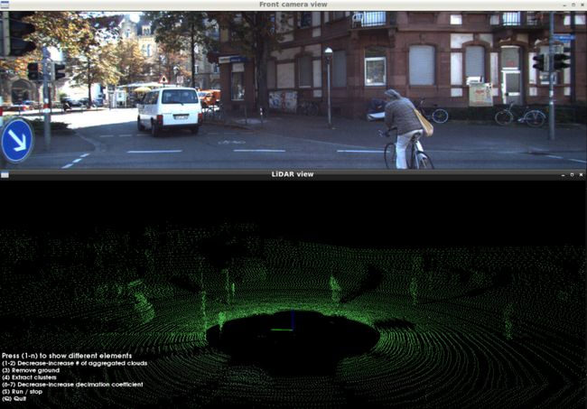
地面移除后:
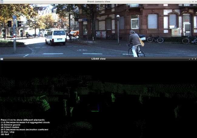
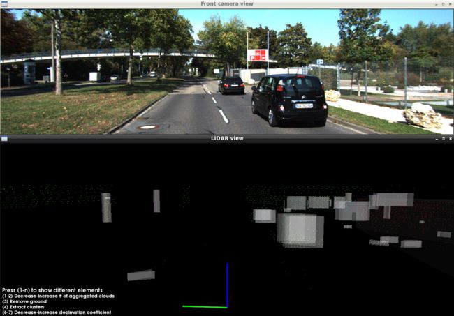
移除地面后,我们准备对剩余的点进行聚类,并通过凸包提取来压缩对象元数据。这两个阶段应该有自己的文章。我将在即将到来的第二部分中介绍它们的实现。同时下面是聚类的最终结果——凸包提取。
可视化的最终对象:
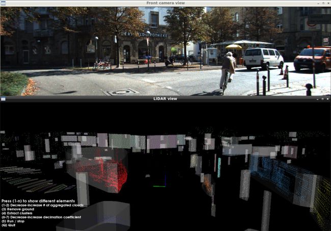
凸包绝对是任何跟踪器都渴望接受作为其输入的元数据类型。它们在RAM使用方面更加紧凑,并且比定向边界框更准确地表示对象的边界。
KITTI 0003中的聚类点云:
结论
我相信,在生活质量和整体生产力方面,自动驾驶将是人类的一次飞跃。
参考资料:
[1] Github上的源代码:https://github.com/Obs01ete/lidar_course/tree/master/src
[2] KITTI :http://www.cvlibs.net/datasets/kitti/eval_tracking.php
[3] 点云处理库PCL:https://pointclouds.org/
感谢阅读!
☆ END ☆
如果看到这里,说明你喜欢这篇文章,请转发、点赞。微信搜索「uncle_pn」,欢迎添加小编微信「 woshicver」,每日朋友圈更新一篇高质量博文。
↓扫描二维码添加小编↓
