ARM_SMMU_下
SMMU驱动代码分析
本文主要分析linux kernel中SMMUv3的代码(drivers/iommu/arm-smmu-v3.c)
linux kernel版本是linux 5.7, 体系结构是aarch64
SMMU的作用是把CPU提交给设备的VA地址,直接作为设备发出的地址,变成正确的物理地址,访问到物理内存上。和 mmu 不同的是,一个 smmu 可以有多个设备连着,他们的页表不可能复用,SMMU 用 stream id 作区分。一个设备有多个进程,所以 smmu 单元也要支持多页表,smmu 使用substream id 区分多进程的页表。
smmu的设备节点定义
在讨论smmu的代码前,先看下smmu的设备节点是怎么定义的
smmu@2b400000 {
                compatible = "arm,smmu-v3";
                reg = <0x0 0x2b400000 0x0 0x20000>;
                interrupts = <GIC_SPI 74 IRQ_TYPE_EDGE_RISING>,
                             <GIC_SPI 75 IRQ_TYPE_EDGE_RISING>,
                             <GIC_SPI 77 IRQ_TYPE_EDGE_RISING>,
                             <GIC_SPI 79 IRQ_TYPE_EDGE_RISING>;
                interrupt-names = "eventq", "priq", "cmdq-sync", "gerror";
                dma-coherent;
                #iommu-cells = <1>;
                msi-parent = <&its 0xff0000>;
        };
compatible: 用于匹配smmu驱动。
reg:smmu设备的物理基地址。
interrupts: 描述与中断名称对应的smmu中断源,上述分别对应中断类型,中断号以及中断触发方式。
interrupt-names: 中断名称。
eventq,当event queue从空变为非空状态时上报中断。
priq, 当pri queue从空变为非空状态时上报中断。
cmdq-sync, command queue中CMDQ_SYNC命令完成时产生中断。
gerror,event记录到event queue过程中产生的错误会记录在SMMU_GERROR寄存器中,并产生中断。
combined,组合中断,需要硬件支持,如果提供了组合中断,则将优先使用组合中断。
dma-coherent:表示设备通过smmu进行的DMA访问是否cache coherent的,假设DMA把外设的数据搬运到内存的某个位置,cpu去读那段地址,因为cache命中了,读到的还是旧的值,这就是cache的不coherent。
#iommu-cells: 一个cell代表一个streamid, smmu-v3必须定义为1。
msi-parent:指定msi中断控制器。
struct arm_smmu_domain {
    struct arm_smmu_device      *smmu;
    struct mutex            init_mutex; /* Protects smmu pointer */

    struct io_pgtable_ops       *pgtbl_ops;
    bool                non_strict;
    atomic_t            nr_ats_masters;

    enum arm_smmu_domain_stage  stage;
    union {
        struct arm_smmu_s1_cfg  s1_cfg;
        struct arm_smmu_s2_cfg  s2_cfg;
    };
    struct iommu_domain     domain;
    struct list_head        devices;
    spinlock_t          devices_lock;
};
arm_smmu_device: 指定smmu设备
io_pgtable_ops: io页表映射定义的一系列操作
non_strict: smmu non-strict模式,在该补丁集中引入 add non-strict mode support for arm-smmu-v3,
主要是为了解决开启smmu后,频繁的unmap,需要频繁的invalid tlb带来的性能损失, 所以不在每一次unmap后都进行tlb invalidate操作,而是累计一定次数或者时间后执行invalid all操作,但这样是有一定的安全风险(页表虽然释放了但是还是在tlb中有残留,可能被利用到)。可以通过启动参数控制。
nr_ats_masters: ats的设备数量,enable_ats时数量+1, disable ats时数量减1
arm_smmu_domain_stage: 代表smmu支持的方式,支持stage1的转换,stage2的转换,stage1 + stage2的转换,以及bypass模式。
arm_smmu_s1_cfg: stage1转换需要的数据结构
arm_smmu_s2_cfg: stage2转换需要的数据结构
smmu驱动初始化
static int arm_smmu_device_probe(struct platform_device *pdev)
{
	int irq, ret;
	struct resource *res;
	resource_size_t ioaddr;
	struct arm_smmu_device *smmu;
	struct device *dev = &pdev->dev;
	bool bypass;

	smmu = devm_kzalloc(dev, sizeof(*smmu), GFP_KERNEL);
	if (!smmu)
		return -ENOMEM;
	smmu->dev = dev;

	if (dev->of_node) {
		ret = arm_smmu_device_dt_probe(pdev, smmu);
	} else {
		ret = arm_smmu_device_acpi_probe(pdev, smmu);
		if (ret == -ENODEV)
			return ret;
	}

	/* Set bypass mode according to firmware probing result */
	bypass = !!ret;

	/* Base address */
	res = platform_get_resource(pdev, IORESOURCE_MEM, 0);
	if (!res)
		return -EINVAL;
	if (resource_size(res) < arm_smmu_resource_size(smmu)) {
		dev_err(dev, "MMIO region too small (%pr)\n", res);
		return -EINVAL;
	}
	ioaddr = res->start;

	/*
	 * Don't map the IMPLEMENTATION DEFINED regions, since they may contain
	 * the PMCG registers which are reserved by the PMU driver.
	 */
	smmu->base = arm_smmu_ioremap(dev, ioaddr, ARM_SMMU_REG_SZ);
	if (IS_ERR(smmu->base))
		return PTR_ERR(smmu->base);

	if (arm_smmu_resource_size(smmu) > SZ_64K) {
		smmu->page1 = arm_smmu_ioremap(dev, ioaddr + SZ_64K,
					       ARM_SMMU_REG_SZ);
		if (IS_ERR(smmu->page1))
			return PTR_ERR(smmu->page1);
	} else {
		smmu->page1 = smmu->base;
	}

	/* Interrupt lines */

	irq = platform_get_irq_byname_optional(pdev, "combined");
	if (irq > 0)
		smmu->combined_irq = irq;
	else {
		irq = platform_get_irq_byname_optional(pdev, "eventq");
		if (irq > 0)
			smmu->evtq.q.irq = irq;

		irq = platform_get_irq_byname_optional(pdev, "priq");
		if (irq > 0)
			smmu->priq.q.irq = irq;

		irq = platform_get_irq_byname_optional(pdev, "gerror");
		if (irq > 0)
			smmu->gerr_irq = irq;
	}
	/* Probe the h/w */
	ret = arm_smmu_device_hw_probe(smmu);
	if (ret)
		return ret;

	/* Initialise in-memory data structures */
	ret = arm_smmu_init_structures(smmu);
	if (ret)
		return ret;

	/* Record our private device structure */
	platform_set_drvdata(pdev, smmu);

	/* Check for RMRs and install bypass STEs if any */
	arm_smmu_rmr_install_bypass_ste(smmu);

	/* Reset the device */
	ret = arm_smmu_device_reset(smmu, bypass);
	if (ret)
		return ret;

	/* And we're up. Go go go! */
	ret = iommu_device_sysfs_add(&smmu->iommu, dev, NULL,
				     "smmu3.%pa", &ioaddr);
	if (ret)
		return ret;

	ret = iommu_device_register(&smmu->iommu, &arm_smmu_ops, dev);
	if (ret) {
		dev_err(dev, "Failed to register iommu\n");
		goto err_sysfs_remove;
	}

	ret = arm_smmu_set_bus_ops(&arm_smmu_ops);
	if (ret)
		goto err_unregister_device;

	return 0;

err_unregister_device:
	iommu_device_unregister(&smmu->iommu);
err_sysfs_remove:
	iommu_device_sysfs_remove(&smmu->iommu);
	return ret;
}
+->arm_smmu_device_probe() //smmu设备驱动probe入口函数
    +-> arm_smmu_device_dt_probe() //smmu设备树解析
    +-> platform_get_irq_byname() // smmu设备中断解析
    +-> arm_smmu_device_hw_probe() // smmu硬件规格探测
    +-> arm_smmu_init_structures() //smmu 数据结构初始化
    +-> arm_smmu_device_reset() // smmu设备复位, 硬件初始化配置
    +-> iommu_device_register() // iommu设备注册
    +-> arm_smmu_set_bus_ops() // 给支持的总线设置bus->iommu_ops
1.arm_smmu_device_dt_probe
static int arm_smmu_device_dt_probe(struct platform_device *pdev,
				    struct arm_smmu_device *smmu)
{
	struct device *dev = &pdev->dev;
	u32 cells;
	int ret = -EINVAL;

	if (of_property_read_u32(dev->of_node, "#iommu-cells", &cells))
		dev_err(dev, "missing #iommu-cells property\n");
	else if (cells != 1)
		dev_err(dev, "invalid #iommu-cells value (%d)\n", cells);
	else
		ret = 0;

	parse_driver_options(smmu);

	if (of_dma_is_coherent(dev->of_node))
		smmu->features |= ARM_SMMU_FEAT_COHERENCY;

	return ret;
}
a. 读取设备树,看smmu的设备节点定义中#iommu-cells是否为1, 如果不为1则直接bypass 掉smmu
b. parse_driver_options, 主要解析smmu是否有需要规避的硬件bug
c. 解析smmu设备中的dma-coherent属性
2. platform_get_irq_byname
/* Interrupt lines */
    irq = platform_get_irq_byname_optional(pdev, "combined");
    if (irq > 0)
        smmu->combined_irq = irq;
    else {
        irq = platform_get_irq_byname_optional(pdev, "eventq");
        if (irq > 0)
            smmu->evtq.q.irq = irq;

        irq = platform_get_irq_byname_optional(pdev, "priq");
        if (irq > 0)
            smmu->priq.q.irq = irq;

        irq = platform_get_irq_byname_optional(pdev, "gerror");
        if (irq > 0)
            smmu->gerr_irq = irq;
    }
分别获取dts节点中定义的"combined", “eventq”, “priq”, "gerror"中断号
3.arm_smmu_device_hw_probe
该函数主要探测smmu设备的硬件规格,主要是通过读SMMU的IDR0,IDR1,IDR5寄存器确认
4.arm_smmu_init_structures
smmu相关的数据结构的内存申请和初始化
static int arm_smmu_init_structures(struct arm_smmu_device *smmu)
{
    int ret;

    ret = arm_smmu_init_queues(smmu); ----------------- (a)
    if (ret)
        return ret;

    return arm_smmu_init_strtab(smmu);  ----------------- (b)
}
(a) arm_smmu_init_queues()
会初始化三个queue, 分别为cmd queue, event queue, pri queue.
SMMU使用这3个队列做基本的事件管理。
event queue用于记录软件配置错误的状态信息,smmu将配置错误信息记录到event queue中,软件会通过从event queue读取配置错误信息,然后进行相应的配置错误处理。
软件使用command queue和smmu 硬件进行交互,软件写命令发送到command queue中,smmu会从command queue中读取命令进行处理。
pri queue需要硬件支持pri 特性,和event queue类似,当有相应硬件事件发生时,硬件把相应的描述符写入pri queue, 然后上报中断。
(b) arm_smmu_init_strtab
static int arm_smmu_init_strtab(struct arm_smmu_device *smmu)
{
    u64 reg;
    int ret;

    if (smmu->features & ARM_SMMU_FEAT_2_LVL_STRTAB)
        ret = arm_smmu_init_strtab_2lvl(smmu);
    else
        ret = arm_smmu_init_strtab_linear(smmu);

    if (ret)
        return ret;

    /* Set the strtab base address */
    reg  = smmu->strtab_cfg.strtab_dma & STRTAB_BASE_ADDR_MASK;
    reg |= STRTAB_BASE_RA;
    smmu->strtab_cfg.strtab_base = reg;

    /* Allocate the first VMID for stage-2 bypass STEs */
    set_bit(0, smmu->vmid_map);
    return 0;
}
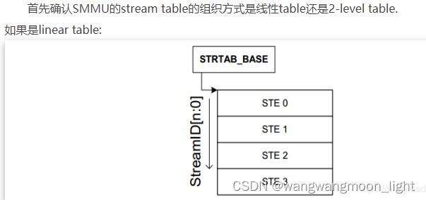
首先确认SMMU的stream table的组织方式是线性table还是2-level table.
如果是linear table:
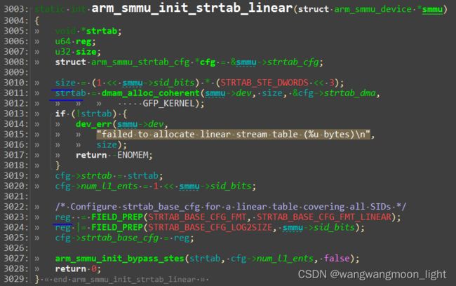
**arm_smmu_init_strtab_linear**
    // 计算stream table的size, 如果使用linear 查找,stream table的size = sid * 64(sid表示有多少个ste, 一个STE的大小为64B)
    size = (1 << smmu->sid_bits) * (STRTAB_STE_DWORDS << 3);
    // 申请Stream table的内存
    strtab = dmam_alloc_coherent()
    // 配置stream table(STRTAB_BASE_CFG)的format, 决定stream table的格式是linear
    reg  = FIELD_PREP(STRTAB_BASE_CFG_FMT, STRTAB_BASE_CFG_FMT_LINEAR);
    // 配置stream table(STRTAB_BASE_CFG)的log2size, ste的entry数目是2 ^ log2size
    reg |= FIELD_PREP(STRTAB_BASE_CFG_LOG2SIZE, smmu->sid_bits);
    // cfg->num_l1_ents对应的是sid, 对SMMU下的所有sid逐一调用arm_smmu_write_strtab_ent
    arm_smmu_init_bypass_stes(strtab, cfg->num_l1_ents)
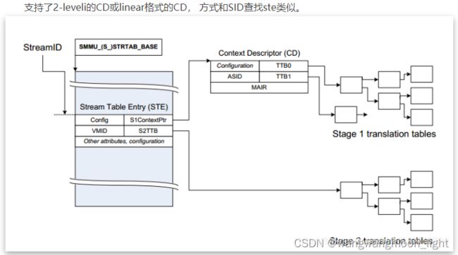
如果是2-level table:

先通过sid的高位找到L1_STD(STRTAB_BASE + sid[9:8] * 8, 一个L1_STD的大小为8B), L1_STD定义了下一级查找的基地址,然后通过sid 找到具体的STE(l2ptr + sid[7:0] * 64).
+-> arm_smmu_init_strtab_2lvl()
/* 计算l1的大小, 一个l1 std的大小为8byte, 对应的l1_std = sid[maxbit:split], maxbit是log2Size - 1, 所以l1的大小等于2 ^ (log2Size - split) * 8 */
l1size = cfg->num_l1_ents * (STRTAB_L1_DESC_DWORDS << 3);
// 申请L1 stream table的空间
strtab = dmam_alloc_coherent()
// 配置stream table(STRTAB_BASE_CFG)的format, 决定stream table的格式是2-level
reg = FIELD_PREP(STRTAB_BASE_CFG_FMT, STRTAB_BASE_CFG_FMT_2LVL);
/* 配置stream table(STRTAB_BASE_CFG)的log2size,2级ste的entry是2 ^ log2size, l1 std的
entry大小为2 ^ (log2size - split) */
reg |= FIELD_PREP(STRTAB_BASE_CFG_LOG2SIZE, size);
/* 配置stream table(STRTAB_BASE_CFG)的split, split的值可以被配置为6/8/10,
分别对应l1 std能够指向的最大二级ste的空间为4k/16k/64k*/
reg |= FIELD_PREP(STRTAB_BASE_CFG_SPLIT, STRTAB_SPLIT);
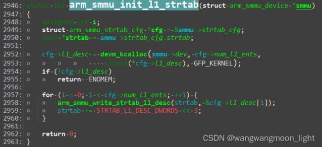
/* 分配L1STD的内存, 并配置L1 descriptor的SPAN,SPAN表示L2 table包含多少个STE */
arm_smmu_init_l1_strtab()
申请 L1 Stream table 的内存,内存大小为2 ^ (log2Size - split) * 8
申请 L1 STD 的内存, L1 STD在 stream table 的索引是 streamID[maxbit: split]
配置完stream table的结构和各级大小后,再配置stream table的基地址:
配置完 stream table 的结构和各级大小后,再配置 stream table 的基地址
5.arm_smmu_device_reset
该函数主要是进行smmu的硬件配置
	arm_smmu_device_reset()
    // 写SMMU_CR0来disable smmu,并通过SMMU_CR0ACK检查CR0是否被clear
    arm_smmu_device_disable()
    // 配置读取ste和command queue的属性
    writel_relaxed(ARM_SMMU_CR1);
    // random crap
    writel_relaxed(ARM_SMMU_CR2);
    /* 配置ARM_SMMU_STRTAB_BASE和ARM_SMMU_STRTAB_BASE寄存器,分别对应stream table的物理基地址
      以及格式,大小等*/
    writeq_relaxed(smmu->strtab_cfg.strtab_base, ARM_SMMU_STRTAB_BASE);
    writel_relaxed(smmu->strtab_cfg.strtab_base_cfg, ARM_SMMU_STRTAB_BASE);
    /* 配置cmd queue相关寄存器
     * ARM_SMMU_CMDQ_BASE是配置command queue的基地址
     * ARM_SMMU_CMDQ_PROD, 可以表示取出命令的位置
     * ARM_SMMU_CMDQ_CONS, 可以表示输入命令的位置
     * ARM_SMMU_CMDQ_PROD和ARM_SMMU_CMDQ_CONS初始化时配置为相同的值,都为0
     * 通过CMDQ_PROD和CMDQ_CONS, 可以判断command queue是否还有空间
     */
    writeq_relaxed(smmu->cmdq.q.q_base, smmu->base + ARM_SMMU_CMDQ_BASE);
    writel_relaxed(smmu->cmdq.q.llq.prod, smmu->base + ARM_SMMU_CMDQ_PROD);
    writel_relaxed(smmu->cmdq.q.llq.cons, smmu->base + ARM_SMMU_CMDQ_CONS);
    // 最后配置command queue的en,对command queue进行使能
    enables = CR0_CMDQEN;
    // 配置event queue相关寄存器, 流程和command queue类似
    config event queue
    // 如果支持pri, 则配置pri queue相关寄存器, 流程和上面一致
    config pri queue
    // 申请并使能smmu支持的相关中断(eventq irq, priq irq, gerror irq)
    arm_smmu_setup_irqs()
    // enable smmu, 写SMMU_CR0,并通过SMMU_CR0ACK检查CR0是否被enable
    arm_smmu_write_reg_sync(smmu, enables, ARM_SMMU_CR0, ARM_SMMU_CR0ACK);
再着重讲下smmu的中断注册:arm_smmu_setup_irqs()
+-> arm_smmu_setup_irqs()
    +-> arm_smmu_setup_unique_irqs()
        +-> arm_smmu_setup_msis(smmu);
            +->  arm_smmu_write_msi_msg()
        +-> devm_request_irq(smmu->dev, irq, arm_smmu_gerror_handler,
                       0, "arm-smmu-v3-gerror", smmu);
arm_smmu_write_msi_msg()函数里会去:
配置MSI中断的目的地址
配置MSI的中断数据
配置MSI中断的写地址的属性
配置完成后,当中断产生时,最终会进入中断注册的处理函数, 以gerror的中断处理为例:
arm_smmu_gerror_handler()
    // 读gerror和gerrorrn寄存器,确认gerror中断发生的错误类型
    gerror = readl_relaxed(smmu->base + ARM_SMMU_GERROR);
    gerrorn = readl_relaxed(smmu->base + ARM_SMMU_GERRORN);
    // 完成中断处理后,写gerror和gerrorn对应的的位一致,global中断处理完成
    writel(gerror, smmu->base + ARM_SMMU_GERRORN);
6. iommu_device_register
注册iommu设备,主要设计一个操作,就是将smmu设备添加到iommu_device_list中
int iommu_device_register(struct iommu_device *iommu)
{
    spin_lock(&iommu_device_lock);
    list_add_tail(&iommu->list, &iommu_device_list);
    spin_unlock(&iommu_device_lock);
    return 0;
}
7.arm_smmu_set_bus_ops
给smmu支持的总线设置bus->iommu_ops, 让总线具有了iommu attach的能力
arm_smmu_set_bus_ops(&arm_smmu_ops)
bus_set_iommu(&pci_bus_type, ops);
bus_set_iommu(&amba_bustype, ops);
bus_set_iommu(&platform_bus_type, ops);
arm_smmu_ops结构体定义如下:

主要分析smmu的两个关键操作:arm_smmu_attach_dev和arm_smmu_add_device
arm_smmu_add_device: 将smmu设备添加到总线
arm_smmu_add_device()
    smmu = arm_smmu_get_by_fwnode(fwspec->iommu_fwnode);
    /* for each sid, 如果是2-level ste, 为l2 ste分配内存
     *在之前的init_l1_strtab, 已经初始化了L1_std, L1_STD定义了下一级查找的基地址,
     * 现在可以通过sid 找到具体的STE(l2ptr + sid[7:0] * 64)
     * 这个函数先为每一个sid分配L2_STE的内存, 分配完成后在为每一个SID进行cfg配置
     */
    arm_smmu_init_l2_strtab()
    // 将device和group关联起来
    iommu_device_link()
总线扫描发现了设备,总线的发现流程负责调用iommu_ops(arm_smmu_ops )给这个设备加上iommu_group,然后让iommu_group指向对应的iommu控制器
arm_smmu_attach_dev, 尝试为设备寻找到驱动
arm_smmu_attach_dev()
    // 从iommu_domain 中得到arm_smmu_domain
    smmu_domain = to_smmu_domain(iommu_domain );
    // 一般情况下smmu_domain->smmu = NULL
    // 在arm_smmu_add_device中,我们已经为STE项分配了内存
    arm_smmu_domain_finalise(domain, master);
        // 分配asid
        asids = arm_smmu_bitmap_alloc()
        // 根据smmu stage是stage1还是stage2, 如果smmu domain是stage1
        arm_smmu_domain_finalise_s1()
            // 分配CD table的空间
            arm_smmu_alloc_cd_tables(smmu_domain);
            // 配置CD descriptor的cfg
            cfg->cd.tcr = FIELD_PREP(CTXDESC_CD_0_XXX)...
        // 如果smmu domain是stage2, STE已经包含了页表的s2ttb基地址和vmid,结束
        arm_smmu_domain_finalise_s2()
        finalise_stage_fn(smmu_domain, master, &pgtbl_cfg);
结合代码分析:
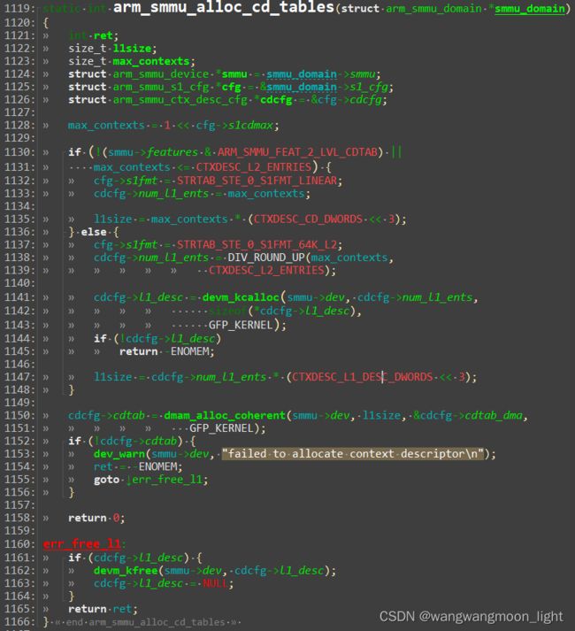
在CD的建立过程中,主要涉及到以下几点:
ste.S1Contextptr中定义了CD的基地址,CD的大小为64byte
a. 需要配置ste.S1CDMax, cdmax为0表示这个ste只有一个CD, 不需要使用到substreamid, 如果cdmax不为0, 那么CD的数目是2 ^ S1CDMax;
b. 需要配置ste.S1Fmt, 如果是linear结构的CD,CD的获取方法为S1ContextPTR + 64 * ssid; 如果是2-level结构的CD, L1CD的索引为ssid[s1cdmax - 1: 6], L2CD的索引为ssid[5:0]
attach_dev完成后,如果是stage1相关,CD的结构,大小和基地址已经成功建立,成功获取STE后,可以通过substreamid找到CD(S1ContextPTR + 64 * ssid)。找到的CD中包含页表PTW需要的TTBR寄存器,所以每一个CD对应一个页表, 这样一个SMMU单元,就可以有多张页表。
总结:
smmu 驱动的初始化流程就是一个探测硬件规格,初始化硬件配置,分配 STD/STE/CD 等空间的过程。
