MIPI CSI2 camera方案(一)camera链路框架
概述:本文重点讨论主控soc(imx8x)上mipi_csi2搭配max96712/max96705/ap0202的完整链路软件框架和实现方案,本文为本人调试过程中记录,如果不对地方欢迎讨论:[email protected]
1.Camera链路完整框架:
链路框架图:

链路简图:

AP0202连接图:
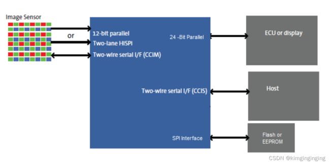
camera模组信息:
ISP : AP0202
Serializer : MAX96705
Deserializer : MAX96712
Output data : YUV422-8bit
Frame Rate : 1920*1080/22fps
I2C地址确定:
max96712:
首次上电通过CFG0上拉情况确定,具体详情如下:

我们电路配置为0xD6,bit0为方向位,所以右移一位后7bit地址为0x6B
DEV_ADDR(0x00)为地址寄存器,可通过0x6B写入新的地址,如写入0x90,实际地址右移掉方向位bit0变为0x48,后续通过该地址操作max96712
max96705:
default addr:0x80,右移一位后就是0x40,在i2c配置分别依次打开lane通道的时候会分别去写入新的地址到reg(0x00)上,LaneA、LaneB、LaneC、LaneD分别设置为0x41,0X42,0X43,0X44.
如下:
regArray[0] = 0x00;
sendBuf[0] = 0x80 + 2 * (i + 1);
i2c_ptr->I2cWrite(0x40, regArray, 1, sendBuf, 1); //分别配置ABCD通道max96705 i2c 地址
note : max96705 有个i2c address translatation功能
//set i2c_source A
regArray[0] = 0x09;
sendBuf[0] = 0xba + 2 * (i + 1);
i2c_ptr->I2cWrite(0x41 + i, regArray, 1, sendBuf, 1);
//set i2c dst A
regArray[0] = 0x0a;
sendBuf[0] = 0xba;
i2c_ptr->I2cWrite(0x41 + i, regArray, 1, sendBuf, 1);
如上例子i=0时候,就是将0xba+2(0xbc,对应的i2c address 是0x5e)转换为0xba,也就是下面说道的ap0202默认地址。i分别从0到3就会分别把0x5e,0x5f,0x60,0x60转换成0xba
AP0202:
![]()
我们的模组默认是连接到VDDIO_H,所以是0xBA,和上面max96705的i2c address translation功能结合就可以达到配置ap0202的目的
2.图像基础
YUV:
分为三个分量,“Y”表示明亮度(Luminance或Luma),也就是灰度值;而“U”和“V” 表示的则是色度(Chrominance或Chroma),作用是描述影像色彩及饱和度,用于指定像素的颜色。
YUV分为planar和packed两种格式,planar格式是先存储所有像素的Y,再存储UV。packed格式每个像素Y,U,V连续交替存储
YCbCr中的Cb标识U,Cr标识V
NV12/NV21(YUV420SP):其他YUV444/YUV422自行扫盲
two-plane模式,Y和UV分别占用一个plane,UV(CbCr)交错存储,U/V的前后顺序区分两者
YUV和RGB转换:
RGB转YUV
Y = 0.298R + 0.612G + 0.117B;
U = -0.168R - 0.330G + 0.498B + 128;
V = 0.449R - 0.435G - 0.083B + 128;
YUV转RGB:
R = Y + 1.4075( V - 128);
G = Y - 0.3455( U - 128) - 0.7169( V - 128);
B = Y + 1.779( U - 128);
3.IMX8 Camera内部框架
IMX8 MIPI-CSI2框图:

IMX8完整链路框图:

概述:
上图为imx8x内部的Display/Camera框架,包括一个MIPI-CSI2(我们重点关心的),一个Parallel接口,两个MIPI-DSI接口,可以看到CSI2接口重点包含MIPI-CSI2、ISI、MJPEG ENCODER、MJPEG DECODER、SSI等几个部分,通过PIXEL LINK、Interconnect方式连接
ISI:
The ISI is responsible for capturing and pre-processing the pixel data from multiple input sources and storing them into the memory,The processing channel performs operations like scaling, color space conversion, de-interlacing, and output buffer control which are configured by the software. The ISI sends the transformed pixel data to the system memory.
Image Sensor Interface (ISI) module interfaces to up to 3 pixel link sources, which may consist of multiple virtual channels, to obtain the image data for processing in 8 independent channels.Each pipeline processes the image line from a configured source and performs one or more functions that are configured by software such as, down scaling, color space conversion, de-interlacing, alpha insertion, 90 and 180 degree rotation, and cropping (horizontal and vertical). The processed image is stored into programmable memory locations.
ISI框图:

8 parallel processing pipelines
Each processing channel comprises of a Scaler, Color Space Conversion (CSC) and Output Buffer Control