Halcon回顾之1D Measuring
基本算子功能介绍
按功能分类介绍:
- 生成边缘提取区域
gen_measure_rectangle2():生成一个垂直于边缘的边缘提取矩形。
gen_measure_arc():生成一个垂直于边缘的边缘提取圆弧。 - 创建fuzzy函数,以使能fuzzy_measure_xxxx算子。
set_fuzzy_measure(): 定义一个fuzzy函数
set_fuzzy_measure_norm_pair(): 为边缘对定义一个归一化的fuzzy函数。
上述两个算子通常需要与下面任意一个算子搭配使用。
create_func_1d_pairs():从(x,y)对集合创建函数
create_funct_1d_arry(): 从y值序列创建函数。 - 提取指定边缘区域的边缘
measure_pairs():根据生成的边缘提取矩形或圆弧来提取边缘对(相当于必须同时提取两个边缘点)。
measure_pos():
fuzzy_measure_pos():
fuzzy_measure_pairing():
fuzzy_measure_pairs(): - 沿着指定边缘区域方向提取图像的平均灰度值
measure_projection():沿着生成的边缘矩形或圆弧提取灰度值轮廓。 - 为了能够重复重复使用已经创建的测量区域,使用如下算子。
translate_measure():平移一个1D测量对象。
write_measure():保存创建的1D测量对象。
read_measure():读取保存的1D测量对象。 - close_measure(): 释放测量对象资源。
关键算子背后的数子逻辑
1D边缘提取的基本流程:
step1: 沿着指定方向获取灰度值(灰度值取指定宽度线上的平均灰度值,如果指定方向存在角度,需要指定插值法)。
step2: 将获取的灰度值序列生成函数,并使用高斯滤波器抑制噪声;
step3: 使用一阶导数的极值点作为边缘候选点,将这些极值点出大于指定阈值的点作为边缘点。
- measure_projection():
通常该算子提取的是沿着测量矩形或圆弧路径的原始像素值,所以为了能够进一步处理必须将得到的灰度值轮廓进行平滑处理:gen_measure_rectangle2(................., MeasureHandle) measure_projection(Image, MeasureHandle, GrayValues) create_funct_1d_arry(GrayValues,Function) // 将数组转换为函数 smooth_funct_1d_gauss(Function,Sigma,SmoothFunction) // 平滑处理 // 通常使用函数的一阶导数、二阶导数进行处理获取极大值极小值等。 // 可以使用funct_1d_to_pairs(SmoothFunction,XValues,YValues)离散化函数 - fuzzy_measure_xxxxx().
核心概念:模糊逻辑的概念可以参考下面的地址链接: link
为了能够更加准确的去检测需要的边缘或者是边缘对。可以使用带有模糊逻辑函数约束的测量算子fuzzy_measure_xxx();
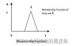
模糊逻辑 - 隶属函数如下所示:
假设定义如下的模糊逻辑函数:
create_funct_1d_pairs([7,9,11],[0,1.1,0.0],sizefunction),就表示7的隶属度为0,9的隶属度为1,11的隶属度为0,8为0.5,10为0.5.
set_fuzzy_measure(MeasureHandle, ‘size’,sizeFunction)
fuzzy_measure_pairs(…,fuzzyThresh:=0.5,…)
那么最后筛选出来的边缘队之间的间距就会返回隶属度大于0.5的值,筛选出的边缘对内的间距应在8至10之间。
推荐使用正则化的模糊逻辑函数创建算子(可以适用于尺寸可变的测量对象):
set_fuzzy_measure_norm_pair();
案例代码与功能拆分
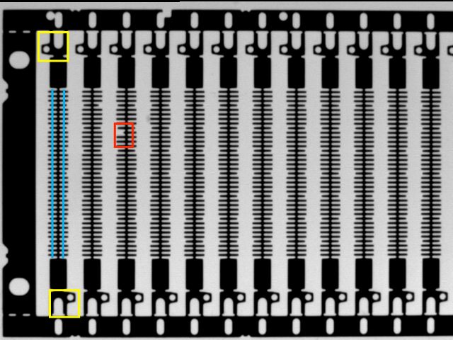
案例的目的,检测下面带有红色标记图像中缺失的部分。

整体的代码逻辑(几乎可以视为1D测量的通用方案):
step1: 创建黄色区域图像的shape模板,同时在蓝色区域创建1D测量矩形。
step2: 使用基于形状的模板匹配方法在带有缺陷的图像中进行匹配,匹配到目标后,将创建的测量矩形和模板区域放射变换到匹配位置。
step3: 自行选择使用任意一种1D测量方法进行边缘直线的提取。
step4: 根据应用需求对测量结果进行处理。
step5: 释放测量对象和模板对象。
* step1: 读取用于创建模板的图像
dev_get_window(WindowHandle);
read_image(ModelImage,'razors1')
get_image_size(ModelImage,Width,Height)
*step2:创建用于创建模板的区域对,使用对的模板精度和速度较于单个region更好。
draw_rectangle1(WindowHandle,row11,column11,row12,column12);
draw_rectangle1(WindowHandle,row21,column21,row22,column22);
gen_rectangle1(ROIpart1,row11,column11,row12,column12)
gen_rectangle1(ROIpart2,row21,column21,row22,column22)
union2(ROIpart1,ROIpart2,ModelROI)

* step3:创建定位模板
reduce_domain(ModelImage,ModelROIO,ImageROI)
create_shape_model(ImageROI,4,0,0,'auto','none','use_polarity',30,10,ModelID)

* step4:获取创建模板的contours轮廓,最后一个参数表示的是金字塔的第几层
get_shape_model_contours(ShapeModel,ModelID,1)

* step5: 创建1D测量区域,使用蓝色区域
gen_rectangle2(MeasureROI1,Rect1Row, Rect1Col, RectPhi, RectLength1, RectLength2)
gen_rectangle2(MeasureROI2,Rect2Row, Rect2Col, RectPhi, RectLength1, RectLength2)

* 为了便于测量对象后续的反复使用,需要用到仿射变换,以及与模板共用同一个仿射变换矩阵,所以通常需要将生成的区域与位于
图像原点的模板保持相对位置不变使用。
area_center(ModelROI,Area,CenterRow,CenterColumn)
move_region(MeasureROI1, MeasureROI1Ref,-CenterRow,-CenterColumn)
move_region(MeasureROIO2,MeasureROI2Ref,-CenterRow,-CenterColumn)

* 这一段代码有点不好理解:下面所得结果为模板中心点与测量矩形中心点之间的偏移距离;
* 1D测量模板移动到原点后,如果直接使用模板后的仿射矩阵,那么移动后的1D模板并不在目标位置,而是存* 在一个下面的一个偏移量,所以还需要将仿射变换后的位置再进行旋转或平移一下偏移才是最终的位置。
DistRect1CenterRow := Rect1Row - CenterROIRow
DistRect1CenterCol := Rect1Col - CenterROIColumn

DistRect2CenterRow := Rect2Row - CenterROIRow
DistRect2CenterCol := Rect2Col - CenterROIColumn

* 生成测量1D对象
 gen_measure_rectangle2 (Rect1Row, Rect1Col, RectPhi, RectLength1, RectLength2, Width, Height, 'bilinear', MeasureHandle1)
    gen_measure_rectangle2 (Rect2Row, Rect2Col, RectPhi, RectLength1, RectLength2, Width, Height, 'bilinear', MeasureHandle2)

* step6: 加载待测量图像
read_image(SearchImage,'razors2')

* step7:进行模板搜索
find_shape_model(SearchImage,ModelID,0,0,0.8,0,0.5,'least_squares',0,0.7,RowCheck,ColumnCheck,AngleCheck,Score)

* step8: 遍历所有匹配到的位置,并将模板区域和1D测量区域仿射变换到检测的新的位置。
if(|Score| > 0)
   for i:=0 to |Score|-1 by 1
   * STEP8.1: 使用点和角度获取原点到模板匹配点之间的仿射变换矩阵,并将模板轮廓转移到当前匹配的位置
   vector_angle_to_rigid(0,0,0,RowCheck[i],ColumnCheck[i],AngleCheck[i],MovementOfObject)
   affine_trans_contour_xld(ShapeModel,ModelAtNewPosition,MovementOfObject)
   * 显示模板到匹配位置
   dev_display(ModelAtNewPosition)
   *Step8.2: 将测量矩形region仿射变换到匹配的位置,用于显示当前的测量位置
   affine_trans_region(MeasureROI1Ref,MeasureROIO1AtNewPosition,MovementOfObject)
   affine_trans_region(MeasureROI2Ref,MeasureROIO2AtNewPosition,MovementOfObject)
   dev_display(MeasureROIO1AtNewPosition)
   dev_display(MeasureROIO2AtNewPosition)

   *step8.3: 将之前生成的测量对象应用于当前的匹配测量区域或者重新生成1D测量对象
    affine_trans_pixel (MovementOfObject, DistRect1CenterRow, DistRect1CenterCol, Rect1RowCheck, Rect1ColCheck)
    affine_trans_pixel (MovementOfObject, DistRect2CenterRow, DistRect2CenterCol, Rect2RowCheck, Rect2ColCheck)

    * 执行测量,检测出边缘对
     translate_measure (MeasureHandle1, Rect1RowCheck, Rect1ColCheck)
     translate_measure (MeasureHandle2, Rect2RowCheck, Rect2ColCheck)
     measure_pairs (SearchImage, MeasureHandle1, 2, 25, 'negative', 'all', RowEdge11, ColEdge11, Amp11, RowEdge21, ColEdge21, Amp21, Width1, Distance1)
     measure_pairs (SearchImage, MeasureHandle2, 2, 25, 'negative', 'all', RowEdge12, ColEdge12, Amp12, RowEdge22, ColEdge22, Amp22, Width2, Distance2)

	* step8.4: 根据测量的结果进行判断
	...............................................
   endfor
endif

* step9: 释放测量对象
close_measure(MeasureHandle1)
close_measure()MeasureHandle2
* step10: 释放模板对象
clear_shape_model(ModelID)
应用扩展实现圆、直线的检测
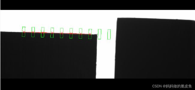
通常1D测量的结果为一个边缘点,为了实现直线和圆的检测可以通过结合gen_contour_polygon_xld与fit_line_contour_xld()或fit_circle_contour_xld()实现。
直线检测代码
基本逻辑:
step1: 沿着要检测的边缘绘制一条直线区域;
step2: 设定需要检测多少个边缘点用于直线拟合;
step3: 生成指定个数的边缘检测矩形;
step4: 生成1D测量对象;
step5: 执行检测;
step6: 使用gen_contour_polygon_xld将检测的边缘点转换为轮廓类型数据
step7: 使用fit_line_contour_xld()执行拟合。
实现代码:
read_image (Realep92, 'C:/Users/Administrator/Desktop/image4.jpg')

* step1:根据指定的检测目标直线生成指定条测量直线
dev_get_window (WindowHandle)
draw_rectangle1 (WindowHandle, Row11, Column11, Row21, Column21)
gen_rectangle1 (Rectangle, Row11, Column11, Row21, Column21)
reduce_domain (Realep92, Rectangle, ImageReduced)
crop_domain (ImageReduced, ImagePart)
dev_display (ImagePart)
draw_line (WindowHandle, Row1, Column1, Row2, Column2)
line_orientation (Row1, Column1, Row2, Column2, AngleLX)
* 根据指定的测量直线数量划分直线
tuple_abs (Column2 - Column1, X_dis)
tuple_abs (Row2 - Row1, Y_dis)

splitePoint:=10
if((splitePoint-1) > 0)
    per_disx := X_dis / (splitePoint-1)
    per_disy := Y_dis / (splitePoint-1)
else
    per_disx := X_dis / 2
    per_disy := Y_dis / 2
endif

MeasureLineStart_row := []
MeasureLineStart_column := []

MeasureLineEnd_row := []
MeasureLineEnd_column := []

* 检测矩形的中心点
MeasureRectangleCenter_row:=[]
MeasureRectangleCenter_column:=[]

dev_set_draw ('margin')
dev_set_color ('red')
dev_set_line_width (1)

for index:=0 to splitePoint-1 by 1
    if(Row1<=Row2)
        temRow := Row1 + per_disy*index
    else
        temRow := Row1 - per_disy*index
    endif

    if(Column1<=Column2)
        temColumn := Column1 + per_disx*index
    else
        temColumn := Column1 - per_disx*index
    endif

    * 计算过划分点的垂直直线的起点
    tuple_cos (AngleLX, Cos)
    MeasureLineStart_row[index] := (temRow -Cos * 100)
     tuple_sin (AngleLX, Sin)
    MeasureLineStart_column[index] := (temColumn -Sin * 100)

    * 计算过划分点的垂直直线的终点
    MeasureLineEnd_row[index] := (temRow + Cos * 100)
    MeasureLineEnd_column[index] := (temColumn + Sin * 100)

    MeasureRectangleCenter_row[index] := temRow
    MeasureRectangleCenter_column[index] := temColumn
endfor

* 显示所有的检测直线区域
* gen_region_line (RegionLines, MeasureLineStart_row, MeasureLineStart_column,  \
               MeasureLineEnd_row, MeasureLineEnd_column)
* dev_display (RegionLines)

* 将检测直线转换为检测矩形
temDr := MeasureLineStart_row - MeasureLineEnd_row
temDc := MeasureLineEnd_column - MeasureLineStart_column
tuple_atan2 (temDr, temDc, TemPhi)
tuple_sqrt (temDr*temDr + temDc*temDc, Sqrt)
TemLen1 := 0.5 * Sqrt
tuple_length (MeasureRectangleCenter_row, Length)
tuple_gen_const (Length, 30, TemLen2)

dev_set_color ('green')
gen_rectangle2 (Rectangle1, MeasureRectangleCenter_row, MeasureRectangleCenter_column, TemPhi, TemLen1, TemLen2)
dev_display (Rectangle1)

* step2: 开始边缘点的检测
get_image_size (ImagePart, Width, Height)

EdgePoint_row := []
EdgePoint_column := []
for index1:=0 to Length-1 by 1
    gen_measure_rectangle2 (MeasureRectangleCenter_row[index1], MeasureRectangleCenter_column[index1], TemPhi[index1], TemLen1[index1], \
                        TemLen2[index1], Width, Height, 'nearest_neighbor', MeasureHandle)

    measure_pos (ImagePart, MeasureHandle, 1, 10, 'all', 'first', RowEdge, ColumnEdge, Amplitude, Distance)

    tuple_length (RowEdge, Length2)
    if(Length2 > 0)
         EdgePoint_row[index1] := RowEdge
         EdgePoint_column[index1] := ColumnEdge
    endif
    close_measure (MeasureHandle)
endfor

* step3: 实现直线拟合
tuple_length (EdgePoint_row, Length1)

if(Length1 > 2)
    dev_set_color ('red')
    gen_region_points (Region, EdgePoint_row, EdgePoint_column)
    gen_cross_contour_xld (Cross, EdgePoint_row, EdgePoint_column, 76, 0.7)
    dev_display (Region)

    gen_contour_polygon_xld (Contour, EdgePoint_row, EdgePoint_column)
    fit_line_contour_xld (Contour, 'tukey', -1, 0, 5, 2, RowBegin, ColBegin, RowEnd, ColEnd, Nr, Nc, Dist)
    gen_region_line (RegionLines, RowBegin, ColBegin, RowEnd, ColEnd)
    count_obj (RegionLines, Number)
endif
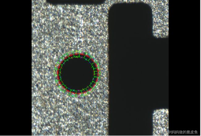
圆检测代码
基本检测逻辑:
step1: 沿着要检测的边缘绘制一条圆弧区域;
step2: 设定需要检测多少个边缘点用于直线拟合;
step3: 生成指定个数的边缘检测矩形;
step4: 生成1D测量对象;
step5: 执行检测;
step6: 使用gen_contour_polygon_xld将检测的边缘点转换为轮廓类型数据
step7: 使用fit_circle_contour_xld执行拟合。
实现代码:
read_image (Realep92, 'C:/Users/Administrator/Desktop/0.jpg.bmp')


* step1:根据指定的检测目标直线生成指定条测量直线
dev_get_window (WindowHandle)
draw_rectangle1 (WindowHandle, Row11, Column11, Row21, Column21)
gen_rectangle1 (Rectangle, Row11, Column11, Row21, Column21)
reduce_domain (Realep92, Rectangle, ImageReduced)
crop_domain (ImageReduced, ImagePart)
dev_display (ImagePart)

draw_circle (WindowHandle, Row, Column, Radius)

* 根据指定测量圆弧去划分测量圆弧段,直接用圆的周长除以测量矩形的宽度就是需要的测量矩阵数
pi:=acos(0.0)*2
circumference:=2*pi*Radius

* 设定测量矩形的宽度为20
splitCircle := circumference / 20
tuple_int (splitCircle, splitCircleInt)

* 获取测量矩形的中心点的直线的起点(园内点)和终点(圆外点)坐标
SmallRadius := Radius - 10
LargeRadius := Radius + 10

MeasureCircleStart_row := []
MeasureCircleStart_column := []

MeasureCircleEnd_row := []
MeasureCircleEnd_column := []

perAngle := 360 / splitCircle
StartAngle :=  perAngle / 2

for index:=0 to splitCircle by 1
    SmallDr := SmallRadius * sin(rad(StartAngle))
    SmallDc := SmallRadius * cos(rad(StartAngle))

    LargeDr := LargeRadius * sin(rad(StartAngle))
    LargeDc := LargeRadius * cos(rad(StartAngle))

    StartAngle := StartAngle + perAngle

    MeasureCircleStart_row[index] := Row - SmallDr
    MeasureCircleStart_column[index] := Column + SmallDc

    MeasureCircleEnd_row[index] := Row - LargeDr
    MeasureCircleEnd_column[index] := Column + LargeDc
endfor
gen_cross_contour_xld (Cross, MeasureCircleStart_row, MeasureCircleStart_column, 10, 0.7)
gen_cross_contour_xld (Cross1, MeasureCircleEnd_row, MeasureCircleEnd_column, 10, 0.7)


* 将检测直线转换为检测矩形
MeasureRectangleCenter_row := 0.5*(MeasureCircleStart_row + MeasureCircleEnd_row)
MeasureRectangleCenter_column := 0.5*(MeasureCircleStart_column + MeasureCircleEnd_column)

temDr := MeasureCircleStart_row - MeasureCircleEnd_row
temDc := MeasureCircleEnd_column - MeasureCircleStart_column

tuple_atan2 (temDr, temDc, TemPhi)
tuple_sqrt (temDr*temDr + temDc*temDc, Sqrt)

TemLen1 := 0.5 * Sqrt
tuple_length (MeasureCircleStart_row, Length)
tuple_gen_const (Length, 10, TemLen2)

dev_set_draw ('margin')
dev_set_color ('green')
gen_rectangle2 (Rectangle1, MeasureRectangleCenter_row, MeasureRectangleCenter_column, TemPhi, TemLen1, TemLen2)
dev_display (Rectangle1)


* step2: 开始边缘点的检测,这里也可以进行优化
get_image_size (ImagePart, Width, Height)
EdgePoint_row := []
EdgePoint_column := []

for index1:=0 to Length-1 by 1
    gen_measure_rectangle2 (MeasureRectangleCenter_row[index1], MeasureRectangleCenter_column[index1], TemPhi[index1], TemLen1[index1], \
                        TemLen2[index1], Width, Height, 'nearest_neighbor', MeasureHandle)

    measure_pos (ImagePart, MeasureHandle, 1, 10, 'all', 'first', RowEdge, ColumnEdge, Amplitude, Distance)
    tuple_length (RowEdge, Length1)
    if(Length1 > 0)
         EdgePoint_row[index1] := RowEdge
         EdgePoint_column[index1] := ColumnEdge
    endif
    close_measure (MeasureHandle)
endfor


* step3: 实现直线拟合,当然这里的拟合过程可以进行更多优化处理
dev_set_color ('red')
gen_region_points (Region, EdgePoint_row, EdgePoint_column)
gen_cross_contour_xld (Cross, EdgePoint_row, EdgePoint_column, 10, 0.7)
dev_display (Region)

gen_contour_polygon_xld (Contour, EdgePoint_row, EdgePoint_column)

fit_circle_contour_xld (Contour, 'algebraic', -1, 0, 0, 3, 2, Row1, Column1, Radius1, \
                        StartPhi, EndPhi, PointOrder)

gen_circle (Circle, Row1, Column1, Radius1)
count_obj (Circle, Number)

