快速入门使用tikz绘制深度学习网络图
【GiantPandaCV导语】本文主要介绍最最最基础的tikz命令和一些绘制CNN时需要的基础的LaTeX知识,希望能在尽可能短的时间内学会并实现使用tikz这个LaTeX工具包来绘制卷积神经网络示意图。
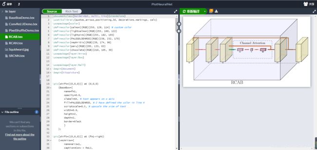
之前看到tikz可以画出这种图,感觉特别专业,所以萌发出了解一下tikz的想法。
1. overleaf平台
在电脑上安装过LaTeX都知道,LaTeX安装包巨大,并且安装速度缓慢,下载和安装的时间需要几乎一下午才能完成。庆幸的是有一个平台可以在线编译文档,那就是overleaf,如今overleaf也推出了中文版本网站:https://cn.overleaf.com/ 以下代码全部是在overleaf平台上编写运行得到的。
最左侧是项目文件列表,中间是代码编辑区,右侧是可视化区,十分方便,只要网络通常,就可以方便地得到结果。并且这个平台提供了好多模板,可以直接使用,太太太太太棒啦。
2. 快速入门tikz
快速熟悉还是要推荐《minimaltikz》这本电子书,可以直接访问http://cremeronline.com/LaTeX/minimaltikz.pdf获取或者在后台回复latex获取。
这本书一共24页,算是尽量压缩了内容了,在这一节中将分析一下其中给的几个例子,用于快速入门:
所有tikz绘制图像的代码都应该在tikzpicture这个环境中使用。
\begin{tikzpicture}
...
\end{tikzpicture}
直角坐标系下:( < a > <a>, < b > <b>)的形式代表二维坐标系中的一个点,单位是cm。
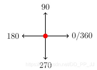
极坐标系下:( < θ > <\theta> <θ>: < r >
\coordinate可以对某个点进行重命名如:
\coordinate (s) at (0,1);
2.1 直线
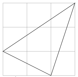
那最基础的画几条线的实现是通过\draw完成:
    \begin{tikzpicture}
    \draw[help lines] (0,0) grid(3,3);
    \coordinate (a) at (0,1);
    \coordinate (b) at (3,3);
    \coordinate (c) at (2,0);
    \draw (a) -- (b) -- (c) --cycle;
    \end{tikzpicture}
–符号代表两点之间的连线,可以连续链接多段。cycle代表让路径回到起点,生成闭合路径。
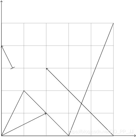
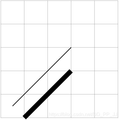
\draw还可以添加选项,比如让线变粗、变红、箭头等需求,都很简单。
\begin{tikzpicture}[scale=1]
\draw[help lines] (0,0) grid(5,5);
\draw (0,0) -- (1,2)--(3,0) --(5,5);
\draw [->] (0,0) -- (2,1);
\draw [<-] (2,3) -- (5,0);
\draw [|->] (0.5,3) -- (0,4);
\draw [<->] (0,6) -- (0,0) -- (6,0);
\end{tikzpicture}
\begin{tikzpicture}
\draw[help lines] (0,0) grid(5,5);
\draw[thick] (0.5, 0.5) -- (3,3);
% [ultra thick, thick, thin, very thick]
\draw[line width=0.2cm] (1,0) -- (3,2);
\end{tikzpicture}
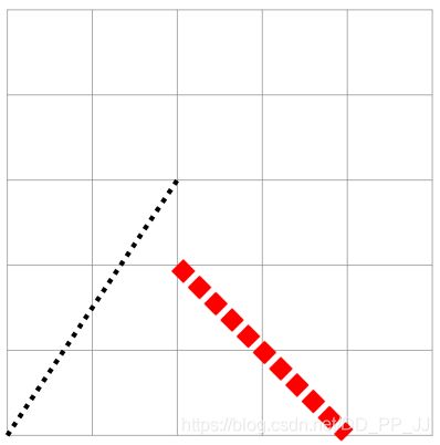
\begin{tikzpicture}
\draw[help lines] (0,0) grid(5,5);
\draw[ultra thick, dotted] (0,0) -- (2,3);
\draw[line width=0.2cm, dotted,red] (2,2) -- (4,0);
%[red, blue, green, cyan, magenta, yellow, black, gray, darkgray, lightgray, browbn, lime, olive, orange, pink, purple, teal, violet, white]
\end{tikzpicture}
2.2 曲线
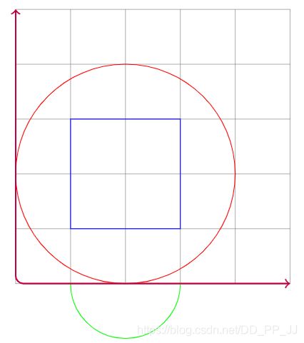
画一些曲线就需要使用circle、rectangle、arc等进行约束。
\begin{tikzpicture}
\draw[help lines] (0,0) grid(5,5);
\draw[blue] (1,1) rectangle(3,3); % 正方形 需要左下角坐标和右上角坐标
\draw[red] (2,2) circle[radius=2]; %圆形 需要圆心坐标和半径
\draw[green] (1,0) arc [radius=1,start angle=180,end angle=360];
\draw[<->, rounded corners, thick, purple] (0,5) -- (0,0) -- (5,0);
\end{tikzpicture}
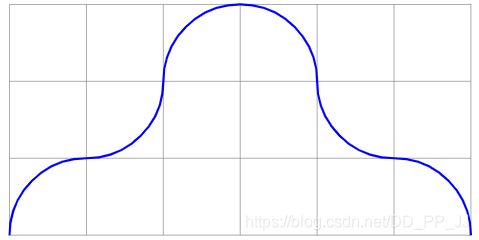
\begin{tikzpicture}
\draw[help lines] (0,0) grid(6,3);
\draw[blue, thick] (0,0) to[out=90,in=180] (1,1) to[in=270,out=360] (2,2)
to[in=180,out=90] (3,3) to[in=90,out=360] (4,2) to[in=180,out=270] (5,1)
to[in=90, out=0] (6,0);
\end{tikzpicture}
这是练习画弧线的时候想练习的一个例子,结果如下
in代表进入的角度,out代表出来时候的角度,为了方便,笔者画了一个辅助图,对照代码方便理解。
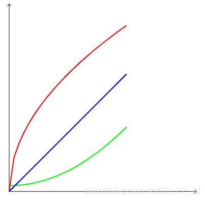
2.3 画函数曲线
\begin{tikzpicture}[xscale=6,yscale=6]
\draw[<->] (0,0.8) -- (0,0) -- (0.8,0);
\draw[green,thick,domain=0:0.5]
plot(\x, {0.025+\x*\x});
\draw[red, thick, domain=0:0.5]
plot(\x, {sqrt(\x)});
\draw[blue, thick, domain=0:0.5]
plot(\x, {abs(\x)});
\end{tikzpicture}
domain限制变量范围,然后可以画图,结果如下:
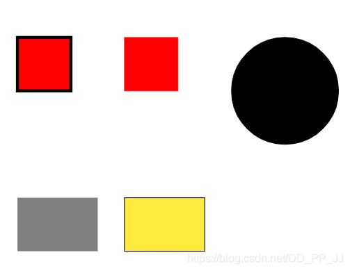
2.4 填充
\begin{tikzpicture}
\draw[fill=red,ultra thick] (0,0) rectangle(1,1);
\draw[fill=red,ultra thin, red] (2,0) rectangle(3,1);
\draw[fill] (5,0) circle[radius=1];
\draw [fill=orange] (9,0) rectangle (11,1);
\draw [fill=white] (9.25,0.25) rectangle (10,1.5);
\path [fill=gray] (0,-2) rectangle (1.5,-3);
\draw [fill=yellow] (2,-2) rectangle (3.5,-3);
\end{tikzpicture}
通过fill参数控制结果,效果如下:
2.6 添加文字
使用\node
\node [] () at () {};
举个例子:
\begin{tikzpicture}[scale=2]
\draw [thick, <->] (0,1) -- (0,0) -- (1,0);
\draw[fill] (1,1) circle [radius=0.025];
\node [below right, red] at (.5,.75) {below right};
\node [above left, green] at (.5,.75) {above left};
\node [below left, purple] at (.5,.75) {below left};
\node [above right, magenta] at (.5,.75) {above right};
\end{tikzpicture}
其实CNN画图主要用的是画一条线的功能,下面来看如何画CNN。
3. 绘制一个CNN模块
对于一个初学者来说,https://github.com/HarisIqbal88/PlotNeuralNet 这个库虽然画的很好,但是难度曲线太高了,退而求其次,使用https://github.com/pprp/SimpleCVReproduction/tree/master/tikz_cnn 进行解析。
首先介绍一个LaTeX中用于封装的命令,\newcommand,当我们不希望写很长的命令,那就需要类似函数的一个方式,封装好固定的操作,根据传入参数完成执行。
\newcommand<命令>[<参数个数>][<首参数默认值>]{<具体的定义>}
举一个例子:
\newcommand\loves[2]{#1 喜欢 #2}
\loves{我}{你}
输出结果就是:我喜欢你
\newcommand{\networkLayer}[9]{
	% Define the macro.
	% 1st argument: Height and width of the layer rectangle slice.
	% 2nd argument: Depth of the layer slice
	% 3rd argument: X Offset --> use it to offset layers from previously drawn layers.
	% 4th argument: Y Offset --> Use it when an output needs to be fed to multiple layers that are on the same X offset.
	% 5th argument: Z Offset --> Use to offset layers from previous
	% 6th argument: Options for filldraw.
	% 7th argument: Text to be placed below this layer.
	% 8th argument: Name of coordinates. When name = "start" this resets the offset counter
	% 9th argument: list of nodes to connect to (previous layers)
	% 全局变量
	\xdef\totalOffset{\totalOffset}
 	\ifthenelse{\equal{#8} {start}}
 	{\FPset{totalOffset}{0}}
 	{}
 	\FPeval\currentOffset{0+(totalOffset)+(#3)}

	\def\hw{#1} % Used to distinguish input resolution for current layer.
	\def\b{0.02}
	\def\c{#2} % Width of the cube to distinguish number of input channels for current layer.
	\def\x{\currentOffset} % X offset for current layer.
	\def\y{#4} % Y offset for current layer.
	\def\z{#5} % Z offset for current layer.
	\def\inText{#7}

    % Define references to points on the cube surfaces
    \coordinate (#8_front) at  (\x+\c  , \z      , \y);
    \coordinate (#8_back) at   (\x     , \z      , \y);
    \coordinate (#8_top) at    (\x+\c/2, \z+\hw/2, \y);
    \coordinate (#8_bottom) at (\x+\c/2, \z-\hw/2, \y);

 	% Define cube coords
	\coordinate (blr) at (\c+\x,  -\hw/2+\z,  -\hw/2+\y); %back lower right
	\coordinate (bur) at (\c+\x,   \hw/2+\z,  -\hw/2+\y); %back upper right
	\coordinate (bul) at (0 +\x,   \hw/2+\z,  -\hw/2+\y); %back upper left
	\coordinate (fll) at (0 +\x,  -\hw/2+\z,   \hw/2+\y); %front lower left
	\coordinate (flr) at (\c+\x,  -\hw/2+\z,   \hw/2+\y); %front lower right
	\coordinate (fur) at (\c+\x,   \hw/2+\z,   \hw/2+\y); %front upper right
	\coordinate (ful) at (0 +\x,   \hw/2+\z,   \hw/2+\y); %front upper left


    % Draw connections from other points to the back of this node
    \ifthenelse{\equal{#9} {}}
 	{} % 为空什么都不做
 	{ % 非空 开始画层与层之间的连线
 	    \foreach \val in #9
 	    % \val = start_front
 	        \draw[line width=0.3mm] (\val)--(#8_back);
 	}

	% Draw the layer body.
	% back plane
	\draw[line width=0.3mm](blr) -- (bur) -- (bul);
	% front plane
	\draw[line width=0.3mm](fll) -- (flr) node[midway,below] {\inText} -- (fur) -- (ful) -- (fll);
	\draw[line width=0.3mm](blr) -- (flr);
	\draw[line width=0.3mm](bur) -- (fur);
	\draw[line width=0.3mm](bul) -- (ful);

	% Recolor visible surfaces
	% front plane
	\filldraw[#6] ($(fll)+(\b,\b,0)$) -- ($(flr)+(-\b,\b,0)$) -- ($(fur)+(-\b,-\b,0)$) -- ($(ful)+(\b,-\b,0)$) -- ($(fll)+(\b,\b,0)$);
	\filldraw[#6] ($(ful)+(\b,0,-\b)$) -- ($(fur)+(-\b,0,-\b)$) -- ($(bur)+(-\b,0,\b)$) -- ($(bul)+(\b,0,\b)$);

	% Colored slice.
	\ifthenelse {\equal{#6} {}}
	{} % Do not draw colored slice if #6 is blank.
	% Else, draw a colored slice.
	{\filldraw[#6] ($(flr)+(0,\b,-\b)$) -- ($(blr)+(0,\b,\b)$) -- ($(bur)+(0,-\b,\b)$) -- ($(fur)+(0,-\b,-\b)$);}

	\FPeval\totalOffset{0+(currentOffset)+\c}

	\draw[ultra thick, red] (#8_back) circle[radius=0.02];
	\node[left] at (#8_back) {back};

	\draw[ultra thick, red] (#8_top) circle[radius=0.02];
	\node[above] at (#8_top) {top};

	\draw[ultra thick, red] (#8_bottom) circle[radius=0.02];
	\node[below] at (#8_bottom) {bottom};

	\draw[ultra thick, red] (#8_front) circle[radius=0.02];
	\node[left] at (#8_front) {front};
}
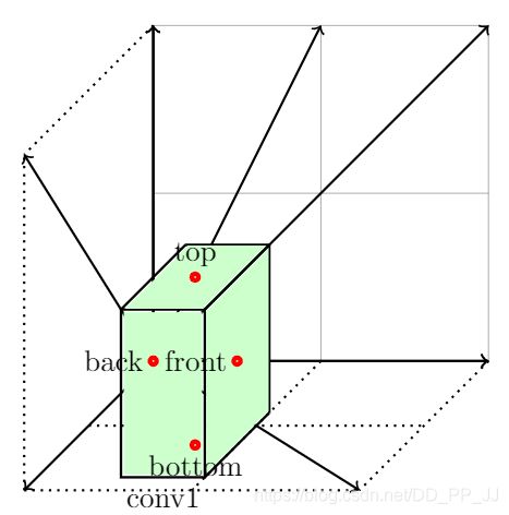
假设以下命令调用,结果会是什么?
\begin{tikzpicture}[scale=2]
\draw[help lines] (0,0) grid(2,2);
\draw[->,thick] (0,0,0) -- (0,0,2);
\draw[->,thick] (0,0,0) -- (0,2,0);
\draw[->,thick] (0,0,0) -- (2,0,0);
\draw[->,thick] (0,0,0) -- (2,2,0);
\draw[->,thick] (0,0,0) -- (1,2,0);
\draw[->,thick] (0,0,0) -- (0,2,2);
\draw[->,thick] (0,0,0) -- (2,0,2);
\draw[dotted,thick] (0,0,2) -- (0,2,2);
\draw[dotted,thick] (0,2,0) -- (0,2,2);
\draw[dotted,thick] (0,0,2) -- (2,0,2);
\draw[dotted,thick] (2,0,0) -- (2,0,2);
\draw[dotted,thick] (1,0,0) -- (1,0,2);
\draw[dotted,thick] (0,0,1) -- (2,0,1);
\draw[<->, thick] (0,2) -- (0,0) -- (2,0);
			%HW -D -  x- y- z - fill color -  text - 坐标 - 链接
\networkLayer{1}{0.5}{0}{0}{0}{color=green!20}{conv1}{}{}
\end{tikzpicture}
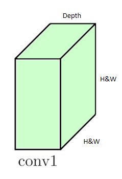
显示结果如下:
卷积神经网络的示意图实际上是一个个立方体构成的,立方体之间可能会有额外连线,代表特征融合;还可能需要题注,为这个特征图立方体进行命名;必须要有立方体的位置信息,长宽高;还需要颜色填充的功能;
综合以上需求,这个函数提供了9个参数分别是:
- #1 H&W 控制立方体右侧这一面的高度,默认为正方形。
- #2 Depth 控制深度
- #3 X 方向上的偏置
- #4 Y方向上的偏置
- #5 Z方向上的偏置
- #6 填充的颜色
- #7 Text展示的文本,放在最下侧
- #8 坐标名称,通过命名便于#9访问
- #9 通过名称指定连接位置,用于连接前方层的时候使用
由于每绘制一个立方体,右侧立方体的X偏置就应该加上左侧立方体的Depth值,这部分代码这样处理的。
\FPset{totalOffset}{0} % 设置全局变量totaloffset
\xdef\totalOffset{\totalOffset}
\ifthenelse{\equal{#8} {start}}
% 如果#8坐标名称为start,那么将totaloffset归零
{\FPset{totalOffset}{0}}
{}% 否则什么都不做
\FPeval\currentOffset{0+(totalOffset)+(#3)}
% 计算当前offset也就是#3 X+totalOffset
赋值过程:
\def\hw{#1} % Used to distinguish input resolution for current layer.
\def\b{0.02}
\def\c{#2} % Width of the cube to distinguish number of input channels for current layer.
\def\x{\currentOffset} % X offset for current layer.
\def\y{#4} % Y offset for current layer.
\def\z{#5} % Z offset for current layer.
\def\inText{#7}
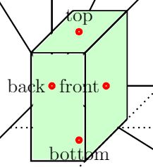
计算立方体表面坐标(将点可视化是额外添加的,为了便于理解)
% Define references to points on the cube surfaces
\coordinate (#8_front) at  (\x+\c  , \z      , \y);
\coordinate (#8_back) at   (\x     , \z      , \y);
\coordinate (#8_top) at    (\x+\c/2, \z+\hw/2, \y);
\coordinate (#8_bottom) at (\x+\c/2, \z-\hw/2, \y);
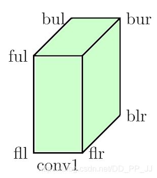
计算7个顶点位置,被挡住的也可以计算,但是因为这里不打算绘制所以不计算。
% Define cube coords
\coordinate (blr) at (\c+\x,  -\hw/2+\z,  -\hw/2+\y); %back lower right
\coordinate (bur) at (\c+\x,   \hw/2+\z,  -\hw/2+\y); %back upper right
\coordinate (bul) at (0 +\x,   \hw/2+\z,  -\hw/2+\y); %back upper left
\coordinate (fll) at (0 +\x,  -\hw/2+\z,   \hw/2+\y); %front lower left
\coordinate (flr) at (\c+\x,  -\hw/2+\z,   \hw/2+\y); %front lower right
\coordinate (fur) at (\c+\x,   \hw/2+\z,   \hw/2+\y); %front upper right
\coordinate (ful) at (0 +\x,   \hw/2+\z,   \hw/2+\y); %front upper left
绘制立方块之间的连线:
% Draw connections from other points to the back of this node
\ifthenelse{\equal{#9} {}}
{} % 为空什么都不做
{ % 非空 开始画层与层之间的连线
\foreach \val in #9
% \val = start_front
\draw[line width=0.3mm] (\val)--(#8_back);
}
绘制立方体主体部分,也就是将7个点连接起来。
% back plane
\draw[line width=0.3mm](blr) -- (bur) -- (bul);
% front plane
\draw[line width=0.3mm](fll) -- (flr) node[midway,below] {\inText} -- (fur) -- (ful) -- (fll);
\draw[line width=0.3mm](blr) -- (flr);
\draw[line width=0.3mm](bur) -- (fur);
\draw[line width=0.3mm](bul) -- (ful);
填充颜色:
% front plane
\filldraw[#6] ($(fll)+(\b,\b,0)$) -- ($(flr)+(-\b,\b,0)$) -- ($(fur)+(-\b,-\b,0)$) -- ($(ful)+(\b,-\b,0)$) -- ($(fll)+(\b,\b,0)$);
\filldraw[#6] ($(ful)+(\b,0,-\b)$) -- ($(fur)+(-\b,0,-\b)$) -- ($(bur)+(-\b,0,\b)$) -- ($(bul)+(\b,0,\b)$);

% Colored slice.
\ifthenelse {\equal{#6} {}}
{} % Do not draw colored slice if #6 is blank.
% Else, draw a colored slice.
{\filldraw[#6] ($(flr)+(0,\b,-\b)$) -- ($(blr)+(0,\b,\b)$) -- ($(bur)+(0,-\b,\b)$) -- ($(fur)+(0,-\b,-\b)$);}
上边的图是通过以下代码生成的:
\begin{tikzpicture}

% INPUT
\networkLayer{3.0}{0.03}{0.0}{0.0}{0.0}{color=gray!80}{}{start}{}

% ENCODER
\networkLayer{3.0}{0.1}{0.5}{0.0}{0.0}{color=white}{conv}{}{}    % S1
\networkLayer{3.0}{0.1}{0.1}{0.0}{0.0}{color=white}{}{}{}        % S2
\networkLayer{2.5}{0.2}{0.1}{0.0}{0.0}{color=white}{conv}{}{}    % S1
\networkLayer{2.5}{0.2}{0.1}{0.0}{0.0}{color=white}{}{}{}        % S2
\networkLayer{2.0}{0.4}{0.1}{0.0}{0.0}{color=white}{conv}{}{}    % S1
\networkLayer{2.0}{0.4}{0.1}{0.0}{0.0}{color=white}{}{}{}        % S2
\networkLayer{1.5}{0.8}{0.1}{0.0}{0.0}{color=white}{conv}{}{}    % S1
\networkLayer{1.5}{0.8}{0.1}{0.0}{0.0}{color=white}{}{}{}        % S2
\networkLayer{1.0}{1.5}{0.1}{0.0}{0.0}{color=white}{conv}{}{}    % S1
\networkLayer{1.0}{1.5}{0.1}{0.0}{0.0}{color=white}{}{mid}{}        % S2

\networkLayer{1.0}{0.5}{1.5}{0.0}{-1.5}{color=green!50}{}{bot}{{mid_front}}
\networkLayer{1.0}{0.5}{-0.5}{0.0}{1.5}{color=green!50}{}{top}{{mid_front}}
\networkLayer{1.0}{0.5}{1.5}{0.0}{0.0}{color=blue!50}{sum}{}{{bot_front,top_front}}

% DECODER
\networkLayer{1.0}{1.5}{0.1}{0.0}{0.0}{color=white}{deconv}{}{} % S1
\networkLayer{1.0}{1.5}{0.1}{0.0}{0.0}{color=white}{}{}{}       % S2
\networkLayer{1.5}{0.8}{0.1}{0.0}{0.0}{color=white}{deconv}{}{} % S1
\networkLayer{1.5}{0.8}{0.1}{0.0}{0.0}{color=white}{}{}{}       % S2
\networkLayer{2.0}{0.4}{0.1}{0.0}{0.0}{color=white}{}{}{}       % S1
\networkLayer{2.0}{0.4}{0.1}{0.0}{0.0}{color=white}{}{}{}       % S2
\networkLayer{2.5}{0.2}{0.1}{0.0}{0.0}{color=white}{}{}{}       % S1
\networkLayer{2.5}{0.2}{0.1}{0.0}{0.0}{color=white}{}{}{}       % S2
\networkLayer{3.0}{0.1}{0.1}{0.0}{0.0}{color=white}{}{}{}       % S1
\networkLayer{3.0}{0.1}{0.1}{0.0}{0.0}{color=white}{}{}{}       % S2

% OUTPUT
\networkLayer{3.0}{0.05}{0.9}{0.0}{0.0}{color=red!40}{}{}{}     % Pixelwise segmentation with classes.

\end{tikzpicture}
需要注意的是#8和#9命令,mid_front代表的是链接#8=mid的front部分,front也可以被top、back、bottom取代。
4. 资源推荐
https://cn.overleaf.com/project/5e8c38c31cccb20001a4998d
https://cn.overleaf.com/project/5f50b21ae802b6000155ec4f
https://github.com/HarisIqbal88/PlotNeuralNet
https://github.com/pprp/SimpleCVReproduction/tree/master/tikz_cnn


