【树莓派 Pico 基于MicroPython编程Thonny开发】
【树莓派 Pico 基于MicroPython编程Thonny开发】
- 1. MicroPython 介绍
- 2. 入门
-
- 2.1 硬件设置
- 2.2 软件设置
- 3. RP2040 连接到 PC 并点亮
-
- 3.1 步骤 1
- 3.2 步骤 2
- 3.3 步骤 3
- 4. IIC 连接RP2040在SSD1306显示
-
- 4.1 硬件连接
- 5. 其他资源
1. MicroPython 介绍
MicroPython是具有部分原生代码编译功能的 Python 解释器。MicroPython 实现了 Python 3.4 和 Python 3.5 及更高版本的一些精选功能,用于嵌入式处理器和受限系统。它与 CPython 不同,您可以在此处阅读有关差异的更多信息。
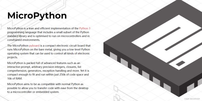
- MicroPython 是 Python 3编程语言的精简高效实现,其中包括 Python 标准库的一小部分,并且经过优化,可在微控制器和受限环境中运行。
- MicroPython pyboard是在裸机上运行 MicroPython 的紧凑型电子电路板,为您提供可用于控制各种电子项目的低级 Python 操作系统。
- MicroPython 充满了高级功能,例如交互式提示、任意精度整数、闭包、列表推导、生成器、异常处理等等。然而,它足够紧凑,可以在 256k 的代码空间和 16k 的 RAM 内安装和运行。
- MicroPython 旨在尽可能与普通 Python 兼容,让您可以轻松地将代码从桌面传输到微控制器或嵌入式系统。

2. 入门
首先,我们将Pi RP2040 连接到计算机,并从 MicroPython 上传一个简单的代码来检查板子是否运行良好。

2.1 硬件设置
- Pi RP2040 x1
- 安卓Micro数据线 x1
- 电脑 x1
2.2 软件设置
-
步骤 1 :根据您的操作系统下载并安装最新版本的Thonny 编辑器

我的是windows,选推荐的第一个,下载地址

-
步骤 2 :启动Thonny
选择简体中文和Pi

-
步骤 3 :点击“切换至一般模式”,重新启动。
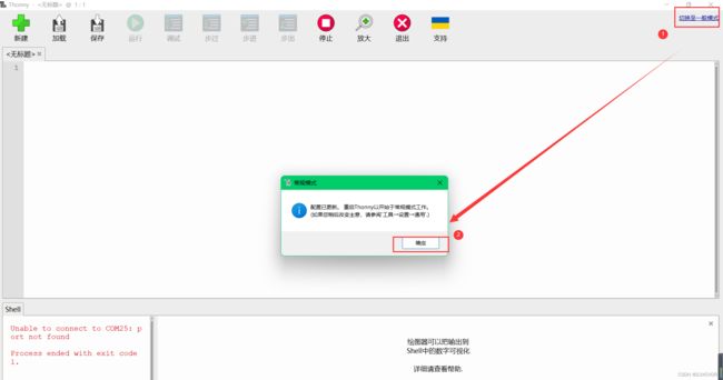
效果如下

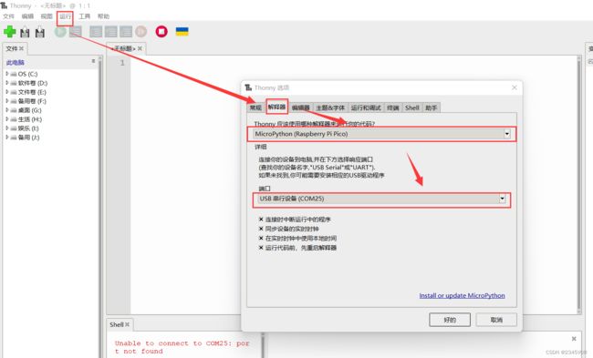
第 4 步。连接Pi Pico,依次选择运行>配置解释器>解释器>端口,选择设备为MicroPython(Raspberry Pi Pico),端口为Try to detect prot automatically
3. RP2040 连接到 PC 并点亮
3.1 步骤 1
按住“BOOT”按钮,然后通过安卓线将RP2040连接到PC。如果运行良好,PC 上会显示“RPI-RP2”桌面。

3.2 步骤 2
按下“停止/重启后端”按钮,将弹出一个窗口,帮助您在板上安装 MicroPython 固件。
为您的开发板下载正确的 MicroPython UF2 文件:
- Raspberry Pi Pico
- Raspberry Pi Pico W
固件完成后,打开设备管理器查看端口。

端口是COM25
3.3 步骤 3
检查解释器是否一致COM25
将以下代码复制到 Thonny。
from machine import Pin, Timer

led = Pin(25, Pin.OUT)
Counter = 0
Fun_Num = 0

def fun(tim):
    global Counter
    Counter = Counter + 1
    print(Counter)
    led.value(Counter%2)

tim = Timer(-1)
tim.init(period=1000, mode=Timer.PERIODIC, callback=fun)
第 4 步。通过单击“运行当前脚本”按钮上传代码。第一次,Thonny 会询问您要将代码文件保存在哪里。This Computer和Raspberry Pi Pico都很好。

如果运行良好,您将看到 LED 灯每秒打开和关闭一次。并且越来越多的输出也将显示在 Shell 中。

4. IIC 连接RP2040在SSD1306显示
在本项目中,我们将通过IIC接口连接Grove - OLED Display 0.96" (SSD1306),在Seeed Studio XIAO RP2040上演示IIC功能。
4.1 硬件连接
步骤 1。下载ssd1306.py库并用 Thonny 打开它。
# MicroPython SSD1306 OLED driver, I2C and SPI interfaces

from micropython import const
import framebuf


# register definitions
SET_CONTRAST = const(0x81)
SET_ENTIRE_ON = const(0xA4)
SET_NORM_INV = const(0xA6)
SET_DISP = const(0xAE)
SET_MEM_ADDR = const(0x20)
SET_COL_ADDR = const(0x21)
SET_PAGE_ADDR = const(0x22)
SET_DISP_START_LINE = const(0x40)
SET_SEG_REMAP = const(0xA0)
SET_MUX_RATIO = const(0xA8)
SET_COM_OUT_DIR = const(0xC0)
SET_DISP_OFFSET = const(0xD3)
SET_COM_PIN_CFG = const(0xDA)
SET_DISP_CLK_DIV = const(0xD5)
SET_PRECHARGE = const(0xD9)
SET_VCOM_DESEL = const(0xDB)
SET_CHARGE_PUMP = const(0x8D)

# Subclassing FrameBuffer provides support for graphics primitives
# http://docs.micropython.org/en/latest/pyboard/library/framebuf.html
class SSD1306(framebuf.FrameBuffer):
    def __init__(self, width, height, external_vcc):
        self.width = width
        self.height = height
        self.external_vcc = external_vcc
        self.pages = self.height // 8
        self.buffer = bytearray(self.pages * self.width)
        super().__init__(self.buffer, self.width, self.height, framebuf.MONO_VLSB)
        self.init_display()

    def init_display(self):
        for cmd in (
            SET_DISP | 0x00,  # off
            # address setting
            SET_MEM_ADDR,
            0x00,  # horizontal
            # resolution and layout
            SET_DISP_START_LINE | 0x00,
            SET_SEG_REMAP | 0x01,  # column addr 127 mapped to SEG0
            SET_MUX_RATIO,
            self.height - 1,
            SET_COM_OUT_DIR | 0x08,  # scan from COM[N] to COM0
            SET_DISP_OFFSET,
            0x00,
            SET_COM_PIN_CFG,
            0x02 if self.width > 2 * self.height else 0x12,
            # timing and driving scheme
            SET_DISP_CLK_DIV,
            0x80,
            SET_PRECHARGE,
            0x22 if self.external_vcc else 0xF1,
            SET_VCOM_DESEL,
            0x30,  # 0.83*Vcc
            # display
            SET_CONTRAST,
            0xFF,  # maximum
            SET_ENTIRE_ON,  # output follows RAM contents
            SET_NORM_INV,  # not inverted
            # charge pump
            SET_CHARGE_PUMP,
            0x10 if self.external_vcc else 0x14,
            SET_DISP | 0x01,
        ):  # on
            self.write_cmd(cmd)
        self.fill(0)
        self.show()

    def poweroff(self):
        self.write_cmd(SET_DISP | 0x00)

    def poweron(self):
        self.write_cmd(SET_DISP | 0x01)

    def contrast(self, contrast):
        self.write_cmd(SET_CONTRAST)
        self.write_cmd(contrast)

    def invert(self, invert):
        self.write_cmd(SET_NORM_INV | (invert & 1))

    def show(self):
        x0 = 0
        x1 = self.width - 1
        if self.width == 64:
            # displays with width of 64 pixels are shifted by 32
            x0 += 32
            x1 += 32
        self.write_cmd(SET_COL_ADDR)
        self.write_cmd(x0)
        self.write_cmd(x1)
        self.write_cmd(SET_PAGE_ADDR)
        self.write_cmd(0)
        self.write_cmd(self.pages - 1)
        self.write_data(self.buffer)


class SSD1306_I2C(SSD1306):
    def __init__(self, width, height, i2c, addr=0x3C, external_vcc=False):
        self.i2c = i2c
        self.addr = addr
        self.temp = bytearray(2)
        self.write_list = [b"\x40", None]  # Co=0, D/C#=1
        super().__init__(width, height, external_vcc)

    def write_cmd(self, cmd):
        self.temp[0] = 0x80  # Co=1, D/C#=0
        self.temp[1] = cmd
        self.i2c.writeto(self.addr, self.temp)

    def write_data(self, buf):
        self.write_list[1] = buf
        self.i2c.writevto(self.addr, self.write_list)


class SSD1306_SPI(SSD1306):
    def __init__(self, width, height, spi, dc, res, cs, external_vcc=False):
        self.rate = 10 * 1024 * 1024
        dc.init(dc.OUT, value=0)
        res.init(res.OUT, value=0)
        cs.init(cs.OUT, value=1)
        self.spi = spi
        self.dc = dc
        self.res = res
        self.cs = cs
        import time

        self.res(1)
        time.sleep_ms(1)
        self.res(0)
        time.sleep_ms(10)
        self.res(1)
        super().__init__(width, height, external_vcc)

    def write_cmd(self, cmd):
        self.spi.init(baudrate=self.rate, polarity=0, phase=0)
        self.cs(1)
        self.dc(0)
        self.cs(0)
        self.spi.write(bytearray([cmd]))
        self.cs(1)

    def write_data(self, buf):
        self.spi.init(baudrate=self.rate, polarity=0, phase=0)
        self.cs(1)
        self.dc(1)
        self.cs(0)
        self.spi.write(buf)
        self.cs(1)
步骤 2。单击“文件→另存为”并将库保存在“Raspberry Pi Pico”中
选择“Raspberry Pi Pico”作为我们保存的位置。
确保保存的文件名为“ssd1306.py”,否则将无法使用。

步骤 3。将以下代码复制到 Thonny。
from ssd1306 import SSD1306_I2C
from machine import Pin, I2C
from time import sleep

i2c = I2C(1, scl=Pin(7), sda=Pin(6), freq=200000)#Grove - OLED Display 0.96" (SSD1315)
oled = SSD1306_I2C(128, 64, i2c)

while True:
    oled.fill(0)#clear
    oled.text("Hello,World!",0,0)
    oled.show()
    #sleep(0.5)
第 4 步。通过单击“运行当前脚本”按钮上传代码。第一次,Thonny 会询问您要将代码文件保存在哪里。This Computer和Raspberry Pi Pico都很好。

接线入下
| 端口A | 板子 | 端口B | 板子 |
|---|---|---|---|
| VCC | SSD1306 | 3V3 | Pico |
| GND | SSD1306 | GND | Pico |
| SCL | SSD1306 | GPIO7 | Pico |
| SDA | SSD1306 | GPIO6 | Pico |
如果运行良好,您将看到文本“Hello,World!” 显示在屏幕上。

5. 其他资源
一些额外的库和示例代码在这里:
[ZIP] XIAO-RP2040-MicroPython-Grove.zip
MicroPython
【树莓派 Pico 基于Arduino IDE编程开发】
【树莓派 Pico 和 Pico W】