【Linux0.11 源码历险记 2】《保护模式》
继续跟着stup.s 来看:
	lidt	idt_48		; load idt with 0,0
	lgdt	gdt_48		; load gdt with whatever appropriate
	...
idt_48:
	.word	0			; idt limit=0
	.word	0,0			; idt base=0L

gdt_48:
	.word	0x800		; gdt limit=2048, 256 GDT entries
	.word	512+gdt,0x9	; gdt base = 0X9xxxx
在实模式下,ds 是段基址,但是在保护模式下,段基址是放在gdt里的,利用ds到gdt里取出每一段的段基址,同时还有一些其他的信息。下面就是一个段描述符的价绍,其实我在另一篇帖子也提到过(https://blog.csdn.net/lyk82698/article/details/127609577)
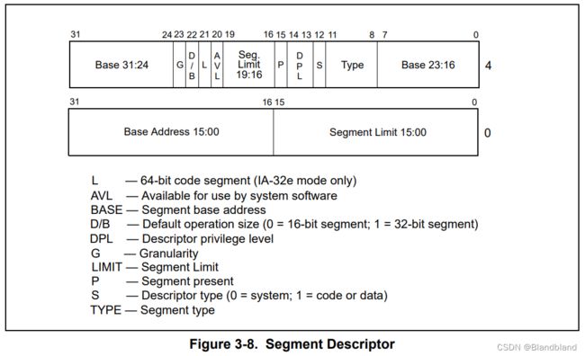
现在去找一个地址,就不再是简单的 ds + 偏移地址了。而是 ds 先去全局描述符表里找到对应的段描述符,然后根据段描述符里的内容作为段基址,结合偏移地址确定最终地址。而全局描述符表的位置,就放在寄存器 gdtr 里面。
| 47-16 | 15-0 |
|---|---|
| gdt起始地址 | gdt的长度限制 |
因此根据下面设置gdtr 表示gdt的限制和起始地址
gdt_48:
	.word	0x800		; gdt limit=2048, 256 GDT entries
	.word	512+gdt,0x9	; gdt base = 0X9xxxx
其中现在的 gdt 如图:
gdt:
	.word	0,0,0,0		; dummy

	.word	0x07FF		; 8Mb - limit=2047 (2048*4096=8Mb)
	.word	0x0000		; base address=0
	.word	0x9A00		; code read/exec
	.word	0x00C0		; granularity=4096, 386

	.word	0x07FF		; 8Mb - limit=2047 (2048*4096=8Mb)
	.word	0x0000		; base address=0
	.word	0x9200		; data read/write
	.word	0x00C0		; granularity=4096, 386
下面开A20 进入保护模式;
	call	empty_8042    ! 测试8042状态寄存器,等待输入缓冲器空,
	mov	al,#0xD1		  ! command write 0xD1命令码表示写数据到8042的P2端口
	out	#0x64,al

	call	empty_8042    !等待输入缓冲器空,看命令是否被接受
	mov	al,#0xDF		  ! A20 on
	out	#0x60,al
	call	empty_8042    !若此时输入缓冲器为空,则表示A20线也选通
为了兼容。早期8086CPU 只有20根线,到32位后,需要向前兼容,一开始是限制地址只能20位的,这里就打开限制。
 well, that went ok, I hope. Now we have to reprogram the interrupts :-(
; we put them right after the intel-reserved hardware interrupts, at
; int 0x20-0x2F. There they won't mess up anything. Sadly IBM really
; messed this up with the original PC, and they haven't been able to
; rectify it afterwards. Thus the bios puts interrupts at 0x08-0x0f,
; which is used for the internal hardware interrupts as well. We just
; have to reprogram the 8259's, and it isn't fun.

	mov	al,#0x11		; initialization sequence
	out	#0x20,al		; send it to 8259A-1
	.word	0x00eb,0x00eb		; jmp $+2, jmp $+2
	out	#0xA0,al		; and to 8259A-2
	.word	0x00eb,0x00eb
	mov	al,#0x20		; start of hardware int's (0x20)
	out	#0x21,al
	.word	0x00eb,0x00eb
	mov	al,#0x28		; start of hardware int's 2 (0x28)
	out	#0xA1,al
	.word	0x00eb,0x00eb
	mov	al,#0x04		; 8259-1 is master
	out	#0x21,al
	.word	0x00eb,0x00eb
	mov	al,#0x02		; 8259-2 is slave
	out	#0xA1,al
	.word	0x00eb,0x00eb
	mov	al,#0x01		; 8086 mode for both
	out	#0x21,al
	.word	0x00eb,0x00eb
	out	#0xA1,al
	.word	0x00eb,0x00eb
	mov	al,#0xFF		; mask off all interrupts for now
	out	#0x21,al
	.word	0x00eb,0x00eb
	out	#0xA1,al
上面就是对8259进行编码。具体咱就不看了。
下面就正式进入保护模式:
mov ax,#0x0001  ; protected mode (PE) bit
lmsw ax      ; This is it;
jmpi 0,8     ; jmp offset 0 of segment 8 (cs)
前两行,将 cr0 这个寄存器的位 0 置 1,模式就从实模式切换到保护模式了。进入保护模式,DS,CS等就变成了段选择子,他们相当于GDT的索引,进入GDT进行选择,同时还带着特权等级。
jmpi 0,8 ; jmp offset 0 of segment 8 (cs)
再往后,又是一个段间跳转指令 jmpi,后面的 8 表示 cs(代码段寄存器)的值,0 表示偏移地址。请注意,此时已经是保护模式了,之前也说过,保护模式下内存寻址方式变了,段寄存器里的值被当做段选择子。
8 用二进制表示就是
00000,0000,0000,1000
对照上面段选择子的结构,可以知道描述符索引值是 1,也就是要去全局描述符表(gdt)中找第一项段描述符。
所以,这里取的就是这个代码段描述符,段基址是 0,偏移也是 0,那加一块就还是 0 咯,所以最终这个跳转指令,就是跳转到内存地址的 0 地址处,开始执行。
下面就要进入 head.s 去执行了。