三层架构冗余实验
1.实验要求:
2.实施——拓扑搭建
3.交换机配置——eth-trunk、trunk干道、VLAN、Stp、SVI、VRRP、DHCP、OSPF(三层架构跑动态协议)
3.1eth-trunk:
sysname SW1
#
interface Eth-Trunk1 创建eth-trunk1
#
interface GigabitEthernet0/0/23 将G0/0/23加入eth-trunk 1
eth-trunk 1
#
interface GigabitEthernet0/0/24 将G0/0/24加入eth-trunk 1
eth-trunk 1
#
interface Eth-Trunk1
port link-type trunk 将eth-trunk1化为trunk并允许VLAN2、3通过
port trunk allow-pass vlan 2 to 3
sysname SW2
#
interface Eth-Trunk1 创建eth-trunk1
#
interface GigabitEthernet0/0/23 将G0/0/23加入eth-trunk 1
eth-trunk 1
#
interface GigabitEthernet0/0/24 将G0/0/24加入eth-trunk 1
eth-trunk 1
#
interface Eth-Trunk1
port link-type trunk 将eth-trunk1化为trunk并允许VLAN2、3通过
port trunk allow-pass vlan 2 to 3
3.2交换机上其他接口的配置
sysname SW1
#
vlan batch 2 to 3 100
#
interface GigabitEthernet0/0/1
port link-type access
port default vlan 100
#
interface GigabitEthernet0/0/2
port link-type trunk
port trunk allow-pass vlan 2 to 3
#
interface GigabitEthernet0/0/3
port link-type trunk
port trunk allow-pass vlan 2 to 3
sysname SW2
#
vlan batch 2 to 3 100
#
interface GigabitEthernet0/0/1
port link-type access
port default vlan 100
#
interface GigabitEthernet0/0/2
port link-type trunk
port trunk allow-pass vlan 2 to 3
#
interface GigabitEthernet0/0/3
port link-type trunk
port trunk allow-pass vlan 2 to 3
sysname SW3
#
vlan batch 2 to 3
#
interface GigabitEthernet0/0/1
port link-type trunk
port trunk allow-pass vlan 2 to 3
#
interface GigabitEthernet0/0/2
port link-type trunk
port trunk allow-pass vlan 2 to 3
#
interface Ethernet0/0/1
port link-type access
port default vlan 2
#
interface Ethernet0/0/2
port link-type access
port default vlan 3
sysname SW4
#
vlan batch 2 to 3
#
interface GigabitEthernet0/0/1
port link-type trunk
port trunk allow-pass vlan 2 to 3
#
interface GigabitEthernet0/0/2
port link-type trunk
port trunk allow-pass vlan 2 to 3
#
interface Ethernet0/0/1
port link-type access
port default vlan 2
#
interface Ethernet0/0/2
port link-type access
port default vlan 3
3.3Stp配置
SW1
#
stp mode MSTP
stp enable
#
stp region-configuration
region-name A
instance 1 vlan 2
instance 2 vlan 3
active region-configuration
#
stp instance 1 root primary
stp instance 2 root secondary
SW2
#
stp mode MSTP
stp enable
#
stp region-configuration
region-name A
instance 1 vlan 2
instance 2 vlan 3
active region-configuration
#
stp instance 2 root primary
stp instance 1 root secondary
SW3
#
stp mode MSTP
stp enable
#
stp region-configuration
region-name A
instance 1 vlan 2
instance 2 vlan 3
active region-configuration
#
interface Ethernet0/0/1
stp edged-port enable
#
interface Ethernet0/0/2
stp edged-port enable
SW4
#
stp mode MSTP
stp enable
#
stp region-configuration
region-name A
instance 1 vlan 2
instance 2 vlan 3
active region-configuration
#
interface Ethernet0/0/1
stp edged-port enable
#
interface Ethernet0/0/2
stp edged-port enable
3.4SVI配置
SW1
#
interface Vlanif2
ip address 172.16.1.1 255.255.255.128
#
interface Vlanif3
ip address 172.16.1.129 255.255.255.128
#
interface Vlanif100
ip address 172.16.0.1 255.255.255.252
SW2
#
interface Vlanif2
ip address 172.16.1.2 255.255.255.128
#
interface Vlanif3
ip address 172.16.1.130 255.255.255.128
#
interface Vlanif100
ip address 172.16.0.5 255.255.255.252
3.5VRRP配置 (SW1和SW2互为备份,一旦出现故障对方会抢走MSTEER)
SW1
#
interface Vlanif2
ip address 172.16.1.1 255.255.255.128
vrrp vrid 1 virtual-ip 172.16.1.126
vrrp vrid 1 priority 120 定SW1为vlanif2 MSTRER(主)
vrrp vrid 1 track interface GigabitEthernet0/0/1 reduced 30 上行链路追踪发现故障优先级下调30
#
interface Vlanif3
ip address 172.16.1.129 255.255.255.128
vrrp vrid 1 virtual-ip 172.16.1.254
SW2
#
interface Vlanif2
ip address 172.16.1.2 255.255.255.128
vrrp vrid 1 virtual-ip 172.16.1.126
#
interface Vlanif3
ip address 172.16.1.130 255.255.255.128
vrrp vrid 1 virtual-ip 172.16.1.254
vrrp vrid 1 priority 120 定SW2为vlanif3 MSTRER(主)
vrrp vrid 1 track interface GigabitEthernet0/0/1 reduced 30 上行链路追踪发现故障优先级下调30
3.6DHCP
SW1
#
DHCP enable
#
ip pool dhcp
gateway-list 172.16.1.126
network 172.16.1.0 mask 255.255.255.128
dns-list 61.134.1.4
#
ip pool vlan3
gateway-list 172.16.1.254
network 172.16.1.128 mask 255.255.255.128
dns-list 61.134.1.4
#
interface Vlanif2
dhcp select global
#
interface Vlanif3
dhcp select global
SW2
#
DHCP enable
#
ip pool dhcp
gateway-list 172.16.1.126
network 172.16.1.0 mask 255.255.255.128
dns-list 61.134.1.4
#
ip pool vlan3
gateway-list 172.16.1.254
network 172.16.1.128 mask 255.255.255.128
dns-list 61.134.1.4
#
interface Vlanif2
dhcp select global
#
interface Vlanif3
dhcp select global
3.7路由器配置——所有节点均拥有合理的IP地址
sysname R1
#
interface GigabitEthernet0/0/0
ip address 172.16.0.2 255.255.255.252
#
interface GigabitEthernet0/0/1
ip address 172.16.0.6 255.255.255.252
#
interface GigabitEthernet0/0/2
ip address 12.1.1.1 255.255.255.0
#
sysname ISP
#
interface GigabitEthernet0/0/1
ip address 12.1.1.2 255.255.255.0
#
interface LoopBack0
ip address 2.2.2.2 255.255.255.0
3.8起ospf协议
R1
#
ospf 1 router-id 1.1.1.1
area 0.0.0.0
network 172.16.0.2 0.0.0.0
network 172.16.0.6 0.0.0.0
SW1
#
ospf 1 router-id 1.1.1.2
silent-interface all 沉默所有接口
undo silent-interface GigabitEthernet0/0/1 放行G0/0/1
undo silent-interface Eth-Trunk1 放行Eth-Trunk1
undo silent-interface Vlanif100 放行Vlanif100
undo silent-interface Vlanif2 放行Vlanif2
area 0.0.0.0
network 172.16.0.1 0.0.0.0
area 0.0.0.1
network 172.16.1.0 0.0.0.255
SW2
#
ospf 1 router-id 1.1.1.3
silent-interface all 沉默所有接口
undo silent-interface GigabitEthernet0/0/1 放行G0/0/1
undo silent-interface Eth-Trunk1 放行Eth-Trunk1
undo silent-interface Vlanif100 放行Vlanif100
undo silent-interface Vlanif2 放行Vlanif2
area 0.0.0.0
network 172.16.0.5 0.0.0.0
area 0.0.0.1
network 172.16.1.0 0.0.0.255
备注:因为需要沉默汇聚层三层交换机SVI口以及向下的物理接口有很多,所以我们的做法就是直接沉默所有,
然后放行我们需要放行的,还有eth-trunk通道基于每个SVI口都会建一个ospf邻居,而且ospf hello保活包会
每隔10s周期周期收发,占用物理链路带宽,基于以上两点,我们需要沉默所有,放行eth-trunk、 放行vlanif100
(这个是模拟器不支持关闭二层接口配IP地址,所以和路由器连接的接口配成access口,划分到VLAN100,
真的三层交换机支持该功能)放行G0/0/1、放行vlanif2(让SW1和SW2基于vlanif2建个邻居,当然下面的设备
是收不到VLAN2的hello包的,只有eth-trunk1能收到VLAN2的 hello周期保活包)
3.9写静态缺省路由、配NAT实现全网可达
R1
ip route-static 0.0.0.0 0.0.0.0 12.1.1.2
#
acl number 2000
rule 5 permit source 172.16.0.0 0.0.255.255
#
interface GigabitEthernet0/0/2
nat outbound 2000
#
ospf 1 router-id 1.1.1.1
default-route-advertise 引入缺省路由
4测试
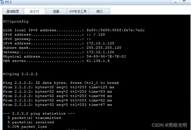
由上图可知,终端获取IP正常,可以访问外网了,SW1/SW2配置了vrrp,我们关闭SW1G0/0/1口
来模拟一下故障,看所有流量能否切换到SW2上来
下图是PC1正常时路径:
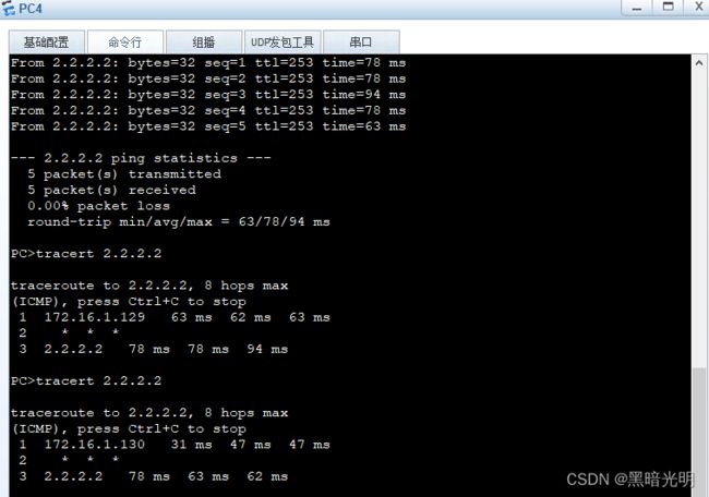
下面我们再关闭SW2上的G0/0/1进行测试:
由上图可知已经成功将所有流量切换到SW1上,下面我们再看一张切换前后对比图片:
5.总结:本实验中三层架构中第一个要注意点是:
①三层架构中根网桥、网关、汇聚要统一,请看下图
由上图可知,如果网关、根网桥不在同一台设备上会出现绕路走的现象,如果都这样走,中间eth-trunk1链路上的负荷会相当重!
②三层架构跑ospf,沉默接口配置必要性,不然整个网络有可能被ospf的hello保活包占用很大一部分带宽,造成占用物理链路带宽和设备硬件资源的浪费
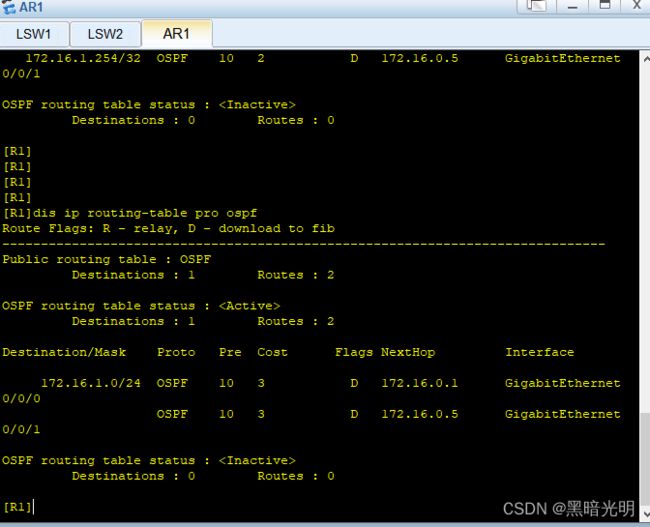
③优化(汇总)本实验里面有两台ABR分别汇总区域1的路由
[SW1-ospf-1-area-0.0.0.1]abr-summary 172.16.1.0 255.255.255.0
[SW2-ospf-1-area-0.0.0.1]abr-summary 172.16.1.0 255.255.255.0
汇总后区域0路由只剩2条
本实验中咱们没配置Telnet或者ssh


