华为路由器 VRRP主备配置
组网需求
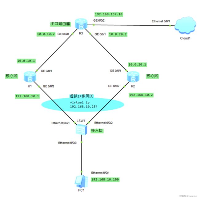
如下图所示,PC1通过SW1双归属到R1和R2。为保证用户的各种业务在网络传输中不中断,需在R1和R2上配置VRRP主备备份功能。
-
正常情况下,主机以R1为默认网关接入Internet,当R1故障时,R2接替R1作为网关继续进行工作,实现网关的冗余备份。
-
R1故障恢复后,其延时20秒通过抢占的方式重新成为Master,承担数据传输。
拓扑图
地址规划
| 机器 | 接口 | IP | 网关 |
| PC1 | 192.168.10.100 | 192.168.10.254 | |
| R1 | G0/0/2 | 192.168.10.1 |
|
| G0/0/1 | 10.0.10.1 | ||
| R2 | G0/0/2 | 192.168.10.2 | |
| G0/0/1 | 10.0.20.1 | ||
| R3 | G0/0/0 | 10.0.10.2 | |
| G0/0/1 | 10.0.20.2 | ||
| G0/0/2 | 192.168.137.10 |
1、R1 路由器
sys
[R1]un in en
[R1]sys R1
[R1]int g0/0/1
[R1-GigabitEthernet0/0/1]ip addr 10.0.10.1 24
[R1-GigabitEthernet0/0/1]int g0/0/2
[R1-GigabitEthernet0/0/2]ip addr 192.168.10.1 24

# 设置 ospf
[R1-GigabitEthernet0/0/2]ospf
[R1-ospf-1]area 0
[R1-ospf-1-area-0.0.0.0]net 192.168.10.0 0.0.0.255
[R1-ospf-1-area-0.0.0.0]net 10.0.10.0 0.0.0.255
[R1-ospf-1-area-0.0.0.0]quit

# 设置 vrrp
[R1-ospf-1]int g0/0/2

# 创建 虚拟IP
[R1-GigabitEthernet0/0/2]vrrp vrid 1 virtual-ip 192.168.10.254

# g0/0/2接口的优先级为120(越大越优先),默认是100
[R1-GigabitEthernet0/0/2]vrrp vrid 1 priority 120

# 设置接口为抢占模式,在故障恢复后延迟20s会抢占会Master的地位
[R1-GigabitEthernet0/0/2]vrrp vrid 1 preempt-mode timer delay 20

# 始终跟踪着g0/0/1端口,如果g0/0/1端口down,会将g0/0/2的优先级自动 -30
[R1-GigabitEthernet0/0/2]vrrp vrid 1 track interface g0/0/1 reduced 30
[R1-GigabitEthernet0/0/2]quit
2、R2 路由器
sys
[R2]un in en
[R2]sys R2
[R2]int g0/0/1
[R2-GigabitEthernet0/0/1]ip addr 10.0.20.1 24
[R2-GigabitEthernet0/0/1]int g0/0/2
[R2-GigabitEthernet0/0/2]ip addr 192.168.10.2 24

# 设置 ospf
[R2-GigabitEthernet0/0/2]ospf
[R2-ospf-1]area 0
[R2-ospf-1-area-0.0.0.0]net 192.168.10.0 0.0.0.255
[R2-ospf-1-area-0.0.0.0]net 10.0.20.0 0.0.0.255
[R2-ospf-1-area-0.0.0.0]quit

# 设置 vrrp
[R2-ospf-1]int g0/0/2
[R2-GigabitEthernet0/0/2]vrrp vrid 1 virtual-ip 192.168.10.254
3、R3 出口路由器
sys
[R3]un in en
[R3]sys R3
[R3]int g0/0/0
[R3-GigabitEthernet0/0/0]ip addr 10.0.10.2 24
[R3-GigabitEthernet0/0/0]int g0/0/1
[R3-GigabitEthernet0/0/1]ip addr 10.0.20.2 24
[R3-GigabitEthernet0/0/1]int g0/0/2
[R3-GigabitEthernet0/0/2]ip addr 192.168.137.10 24

# 设置 ospf
[R3-GigabitEthernet0/0/2]ospf
[R3-ospf-1]area 0
[R3-ospf-1-area-0.0.0.0]net 10.0.10.0 0.0.0.255
[R3-ospf-1-area-0.0.0.0]net 10.0.20.0 0.0.0.255
[R3-ospf-1-area-0.0.0.0]net 192.168.137.0 0.0.0.255
[R3-ospf-1-area-0.0.0.0]quit
4、验证配置结果
完成上述配置以后,在R1和R2上分别执行display vrrp命令,可以看到R1在备份组中的状态为Master,R2在备份组中的状态为Backup
[R1]dis vrrp
  GigabitEthernet0/0/2 | Virtual Router 1
    State : Master
    Virtual IP : 192.168.10.254
    Master IP : 192.168.10.1
    PriorityRun : 120
    PriorityConfig : 120
    MasterPriority : 120
    Preempt : YES   Delay Time : 20 s
    TimerRun : 1 s
    TimerConfig : 1 s
    Auth type : NONE
    Virtual MAC : 0000-5e00-0101
    Check TTL : YES
    Config type : normal-vrrp
    Backup-forward : disabled
    Track IF : GigabitEthernet0/0/1   Priority reduced : 30
    IF state : UP
    Create time : 2023-03-27 17:13:19 UTC-08:00
    Last change time : 2023-03-27 17:21:26 UTC-08:00
[R2]dis vrrp
  GigabitEthernet0/0/2 | Virtual Router 1
    State : Backup
    Virtual IP : 192.168.10.254
    Master IP : 192.168.10.1
    PriorityRun : 100
    PriorityConfig : 100
    MasterPriority : 120
    Preempt : YES   Delay Time : 0 s
    TimerRun : 1 s
    TimerConfig : 1 s
    Auth type : NONE
    Virtual MAC : 0000-5e00-0101
    Check TTL : YES
    Config type : normal-vrrp
    Backup-forward : disabled
    Create time : 2023-03-27 17:13:32 UTC-08:00
    Last change time : 2023-03-27 17:38:02 UTC-08:00
5、 测试网络互通
# 访问出口路由器
[R1]ping 192.168.137.10
  PING 192.168.137.10: 56  data bytes, press CTRL_C to break
    Reply from 192.168.137.10: bytes=56 Sequence=1 ttl=255 time=20 ms
    Reply from 192.168.137.10: bytes=56 Sequence=2 ttl=255 time=20 ms
    Reply from 192.168.137.10: bytes=56 Sequence=3 ttl=255 time=20 ms
    Reply from 192.168.137.10: bytes=56 Sequence=4 ttl=255 time=20 ms
    Reply from 192.168.137.10: bytes=56 Sequence=5 ttl=255 time=20 ms

  --- 192.168.137.10 ping statistics ---
    5 packet(s) transmitted
    5 packet(s) received
    0.00% packet loss
    round-trip min/avg/max = 20/20/20 ms

# 访问 R2 路由器
[R1]ping 10.0.20.1
  PING 10.0.20.1: 56  data bytes, press CTRL_C to break
    Reply from 10.0.20.1: bytes=56 Sequence=1 ttl=254 time=30 ms
    Reply from 10.0.20.1: bytes=56 Sequence=2 ttl=254 time=20 ms
    Reply from 10.0.20.1: bytes=56 Sequence=3 ttl=254 time=30 ms
    Reply from 10.0.20.1: bytes=56 Sequence=4 ttl=254 time=30 ms
    Reply from 10.0.20.1: bytes=56 Sequence=5 ttl=254 time=30 ms

  --- 10.0.20.1 ping statistics ---
    5 packet(s) transmitted
    5 packet(s) received
    0.00% packet loss
    round-trip min/avg/max = 20/28/30 ms
6、模拟 R1 路由器出现故障
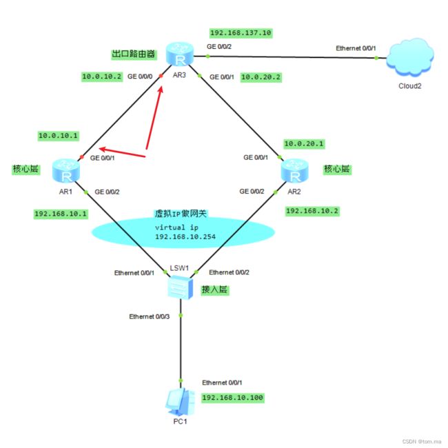
(1)通过上面我知道,现在 Master IP 在 192.168.10.1 R1 路由器上面,现在我们尝试断开 R1 路由器的 g0/0/1 接口
[R1]int g0/0/1
[R1-GigabitEthernet0/0/1]shutdown
(2)再次查看 vrrp,发现Master IP:已经漂移到 192.168.10.2 R2 路由器上面
[R1-GigabitEthernet0/0/1]dis vrrp
  GigabitEthernet0/0/2 | Virtual Router 1
    State : Backup
    Virtual IP : 192.168.10.254
    Master IP : 192.168.10.2
    PriorityRun : 90
    PriorityConfig : 120
    MasterPriority : 100
    Preempt : YES   Delay Time : 20 s
    TimerRun : 1 s
    TimerConfig : 1 s
    Auth type : NONE
    Virtual MAC : 0000-5e00-0101
    Check TTL : YES
    Config type : normal-vrrp
    Backup-forward : disabled
    Track IF : GigabitEthernet0/0/1   Priority reduced : 30
    IF state : DOWN
    Create time : 2023-03-27 17:13:19 UTC-08:00
    Last change time : 2023-03-27 17:54:18 UTC-08:00
(3)我们在 PC1 上面再次访问出口路由器,发现是OK的
PC1>ping 192.168.137.10

Ping 192.168.137.10: 32 data bytes, Press Ctrl_C to break
From 192.168.137.10: bytes=32 seq=1 ttl=254 time=47 ms
From 192.168.137.10: bytes=32 seq=2 ttl=254 time=31 ms
From 192.168.137.10: bytes=32 seq=3 ttl=254 time=32 ms
From 192.168.137.10: bytes=32 seq=4 ttl=254 time=31 ms
From 192.168.137.10: bytes=32 seq=5 ttl=254 time=32 ms

--- 192.168.137.10 ping statistics ---
  5 packet(s) transmitted
  5 packet(s) received
  0.00% packet loss
  round-trip min/avg/max = 31/34/47 ms

