交换综合实验以及链路聚合和VRRP
1. MSTP针对RSTP做了哪些改进?请详细说明
在划分VLAN的网络中运行RSTP/STP。局域网内的所有VLAN共享一棵生成树,被阻塞后的链路将不再承载任何流量。无法在VLAN间实现数据流量的负载均衡;导致带宽利用率、设备资源利用率较低

(1)达成负载均衡
- 通过多生成树收敛不同路径来达成负载均衡
- 对于同一VLAN生成树无法做到负载均衡
(2)划分生成树网络
- 生成树交换网络规模无法做到很大,一般是50个设备的规模
- 区域内部一颗树,区域之间一棵树(把各区域抽象成一台交换机)
(3)MSTP兼容STP和RSTP,既可以快速收敛,又提供了数据转发的多个冗余路径,在数据转发过程中实现VLAN数据的负载均衡。
2. 链路聚合方式有哪些?
两种方式:手工模式和LACP模式
(1)手工模式
- Eth-trunk的建立,成员节口的加入均由手动配置,双方系统间不使用LACP协议进行协商
- 正常情况下所有链路都参与数据的转发,平均分担流量,如果某条活动链路故障,链路聚合组自动在剩余活动链路中平均分担流量。---可以选择负载分担模式
- 当聚合接口两端设备中存在一个不支持LACP协议时,可以使用手工模式
(2)LACP模式
-
采用 LACP 协议的一种链路聚合模式。设备间通过链路聚合控制协议数据单元( Link Aggregation Control Protocol Data Unit , LACPDU )进行交互,通过协议协商确保对端是同一台设 备、同一个聚合接口的成员接口。
-
LACP模式下,两端设备所选择的活动接口必须保持一致,否则链路聚合组将无法建立。此时可以是其中一端成为主动端,另一端(被动端)根据主动端选择活动接口。
-
通过系统LACP的优先级确定主动端,值越小优先级越高
3. 手动聚合与LACP聚合有哪些区别?
(1)手工模式
所有链路都会参与流量转发,设备不支持主备,不支持链路备份,不能检测到端口是否连接错误,不支持跨设备
(2)LACP聚合
支持主备,支持链路备份,可以检测到端口连接错误,支持跨设备
4. 链路的聚合条件是什么?
为了使链路聚合接口正常工作,必须保证本端链路聚合接口中所有成员接口的对端接口:
- 属于同一设备
- 加入同一链路聚合接口
- 华为设备要求,加入聚合口袋成员节口必须具备相同的速率,双工模式,相同的接口类型保活接口放通的VLAN运行列表以及PVID(配置之前不能存在任何配置,聚合后在接口中配置)
5. MSTP如何实现负载均衡?
在数据转发过程中实现对VLAN负载均衡。
MSTP将一个或多个VLAN映射到一个instance(实例),再基于instance计算生成树,映射到同一个instance的VLAN共享同一棵生成树

例:如图中例子,最终生成两棵生成树
instance1对应的生成树以SW1为根交换设备,转发VLAN1-VLAN10的报文
instance2对应的生成树以SW2为根交换设备,转发VLAN11-VLAN20的报文
不同的VLAN报文沿着不同的路径转发,实现了负载分担。
PS:生成树不是基于VLAN运行的,而是基于instance运行的
6. 链路聚合如何实现负载均衡?
为了保证企业网络稳定性,仅进行设备备份是不够的,需要针对链路进行备份。避免出现链路故障导致网路无法正常通信。

以太网链路聚合Eth-Trunk:简称链路聚合,通过物理接口捆绑成一个逻辑接口,在不进行硬件升级的情况下,达到增加链路带宽的目的
7. LACP如何配置稳定的带宽?
(1)LACP:链路聚合控制协议。
LACPDU报文中包含设备优先级、MAC地址、接口优先级、接口号等
(2)工作过程
- LACP模式下,两端设备所选择的活动接口数目必须保持一致,否则链路聚合组就无法建立。此时可以使其中一端成为主动端,另一端(被动端)根据主动端选择活动接口
- 通过系统LACP接口优先级确定主动端,值越小优先级越高
- 选出主动端,两端都以主动端的接口优先级选择活动接口,优先级高的接口优先被选为活动接口。
- LACP支持配置最大活动接口数目,成员接口数目超过最大活动接口数目时会比较接口的优先级,接口号选举较优的接口称为活动接口,其余的成为备份端口(非活动接口),同时对应的链路分别成为活动链路、非活动链路。交换机只会从活动接口发送、接收报文。
- 当活动链路出现链路故障时,可以从非活动链路中找出一条优先级最高(接口优先级、接口编号比较)
8. 详细说明VRRP的工作原理?
- VRRP组中的设备选举出Master。Master设备通过发送免费ARP报文,将虚拟MAC地址通知给与它连接的设备或者主机,从而承担报文转发任务。
- Master设备周期性向备份组内所有Backup设备发送VRRP通告报文。
- 如果Master设备出现故障,VRRP备份组中的Backup设备重新选举新的Master。
- VRRP组状态切换时,Master设备由一台设备切换为另外一台设备,新的Master设备会立即发送携带虚拟路由器的虚拟MAC地址和虚拟IP地址信息的免费ARP报文刷新与它连接的主机或设备中的MAC表项,从而把用户流量引到新的Master设备上来,整个过程对用户完全透明。
- 原Master设备故障恢复时,若该设备为IP地址拥有者(则其优先级为255),将直接切换至Master状态。若该设备优先级小于255,将首先切换至Backup状态,且其优先级恢复为故障前配置的优先级。
- Backup设备的优先级高于Master设备时,由Backup设备的工作方式(抢占方式和非抢占方式)决定是否重新选举Master。(默认抢占值:0 从而出现立即抢占)
9. VRRP如何实现上行链路监控?
VRRP可监视(通过Track配置)上行端口状态,当设备感知到上行端口或者链路发生故障时,可主动减低VRPP优先级,从而保证上行链路正常的Backup设备通过选举切换为Master状态。指导报文转发。

10.交换综合实验

(1)接入层配置
- 将接口划入VLAN
[sw3]vlan batch 2 to 5
[sw3]int g0/0/3
[sw3-GigabitEthernet0/0/3]port link-type access
[sw3-GigabitEthernet0/0/3]port default vlan 2
[sw3]int g0/0/4
[sw3-GigabitEthernet0/0/4]port link-type access
[sw3-GigabitEthernet0/0/4]port default vlan 3
[sw3]port-group group-member g0/0/1 g0/0/2
[sw3-port-group]port link-type trunk
[sw3-GigabitEthernet0/0/1]port link-type trunk
[sw3-GigabitEthernet0/0/2]port link-type trunk
[sw3-port-group]port trunk allow-pass vlan 2
[sw3-port-group]port trunk allow-pass vlan 2 to 5
[sw3-GigabitEthernet0/0/1]port trunk allow-pass vlan 2 to 5
[sw3-GigabitEthernet0/0/2]port trunk allow-pass vlan 2 to 5
[sw3-port-group]undo port trunk allow-pass vlan 1
[sw3-GigabitEthernet0/0/1]undo port trunk allow-pass vlan 1
[sw3-GigabitEthernet0/0/2]undo port trunk allow-pass vlan 1
[sw4]int g0/0/3
[sw4-GigabitEthernet0/0/3]port link-type access
[sw4-GigabitEthernet0/0/3]port default vlan 4
[sw4]int g0/0/4
[sw4-GigabitEthernet0/0/4]port link-type a
[sw4-GigabitEthernet0/0/4]port link-type access
[sw4-GigabitEthernet0/0/4]port default vlan 5
[sw4]port-group group-member g0/0/1 g0/0/2
[sw4-port-group] port link-type trunk
[sw4-GigabitEthernet0/0/1] port link-type trunk
[sw4-GigabitEthernet0/0/2] port link-type trunk
[sw4-port-group] undo port trunk allow-pass vlan 1
[sw4-GigabitEthernet0/0/1] undo port trunk allow-pass vlan 1
[sw4-GigabitEthernet0/0/2] undo port trunk allow-pass vlan 1
[sw4-port-group] port trunk allow-pass vlan 2 to 5
[sw4-GigabitEthernet0/0/1] port trunk allow-pass vlan 2 to 5
[sw4-GigabitEthernet0/0/2] port trunk allow-pass vlan 2 to 5- 将连接PC端的接口划为边缘接口,开启BPDU保护
[sw3]port-group group-member g0/0/3 g0/0/4
[sw3-port-group]stp edged-port enable---将接口划入边缘接口
[sw3-GigabitEthernet0/0/3]stp edged-port enable
[sw3-GigabitEthernet0/0/4]stp edged-port enable
[sw3]stp bpdu-protection---开启BPDU保护
[sw4]port-group group-member g0/0/3 g0/0/4
[sw4-port-group]stp edged-port enable
[sw4-GigabitEthernet0/0/3]stp edged-port enable
[sw4-GigabitEthernet0/0/4]stp edged-port enable
[sw4]stp bpdu-protection
(2)汇聚层配置
- 接口划入VLAN
[sw1]vlan batch 2 to 5
[sw1]port-group group-member g0/0/4 g0/0/5
[sw1-port-group]port link-type trunk
[sw1-GigabitEthernet0/0/4]port link-type trunk
[sw1-GigabitEthernet0/0/5]port link-type trunk
[sw1-port-group] undo port trunk allow-pass vlan 1
[sw1-GigabitEthernet0/0/4] undo port trunk allow-pass vlan 1
[sw1-GigabitEthernet0/0/5] undo port trunk allow-pass vlan 1
[sw1-port-group] port trunk allow-pass vlan 2 to 5
[sw1-GigabitEthernet0/0/4] port trunk allow-pass vlan 2 to 5
[sw1-GigabitEthernet0/0/5] port trunk allow-pass vlan 2 to 5
[sw2]vlan batch 2 to 5
[sw2]port-group group-member g0/0/4 g0/0/5
[sw2-port-group]port link-type trunk
[sw2-GigabitEthernet0/0/4]port link-type trunk
[sw2-GigabitEthernet0/0/5]port link-type trunk
[sw2-port-group] undo port trunk allow-pass vlan 1
[sw2-GigabitEthernet0/0/4] undo port trunk allow-pass vlan 1
[sw2-GigabitEthernet0/0/5] undo port trunk allow-pass vlan 1
[sw2-port-group] port trunk allow-pass vlan 2 to 5
[sw2-GigabitEthernet0/0/4] port trunk allow-pass vlan 2 to 5
[sw2-GigabitEthernet0/0/5] port trunk allow-pass vlan 2 to 5- 配置VLANIF接口,开启DHCP分配地址
[sw1]dhcp enable
[sw1]int vlan 2
[sw1-Vlanif3]ip add 10.1.2.1 24
[sw1-Vlanif3]dhcp select interface
[sw1]int vlan 3
[sw1-Vlanif3]ip add 10.1.3.1 24
[sw1-Vlanif3]dhcp select interface
[sw2]dhcp enable
[sw2]int vlan 4
[sw2-Vlanif4]ip add 10.1.4.1 24
[sw2-Vlanif4]dhcp select interface
[sw2]int vlan 5
[sw2-Vlanif5]ip add 10.1.5.1 24
[sw2-Vlanif5]dhcp select interface- 将汇聚层上层接口划为边缘接口
[sw1]int g0/0/1
[sw1-GigabitEthernet0/0/1]stp edged-port enable
[sw1]stp bpdu-protection
[sw2]int g0/0/1
[sw2-GigabitEthernet0/0/1]stp edged-port enable
[sw2]stp bpdu-protection
(将PC端开启DHCP自动获取IP地址)
- 将SW1和SW2相连的接口划入Eth-trunk 1
[sw1]int Eth-Trunk 1
[sw1-Eth-Trunk1]trunkport g0/0/2
[sw1-Eth-Trunk1]trunkport g0/0/3
[sw1-Eth-Trunk1] port link-type trunk
[sw1-Eth-Trunk1] port trunk allow-pass vlan 2 to 5---因为默认流量在VLAN1上流通,所以此处需要放通VLAN1的流量
[sw2]int Eth-Trunk 1
[sw2-Eth-Trunk1]trunkport g0/0/2
[sw2-Eth-Trunk1]trunkport g0/0/3
[sw2-Eth-Trunk1] port link-type trunk
[sw2-Eth-Trunk1] port trunk allow-pass vlan 2 to 5- 查看配置效果

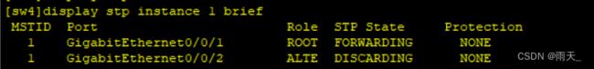


(3)进行MSTP配置
- 基础配置,划分实例
[sw1]stp mode mstp
[sw1]stp region-configuration
[sw1-mst-region] region-name HW
[sw1-mst-region] revision-level 1
[sw1-mst-region] instance 1 vlan 2 to 3
[sw1-mst-region] instance 2 vlan 4 to 5
[sw1-mst-region] active region-configuration
[sw2]stp mode mstp
[sw2]stp region-configuration
[sw2-mst-region] region-name HW
[sw2-mst-region] revision-level 1
[sw2-mst-region] instance 1 vlan 2 to 3
[sw2-mst-region] instance 2 vlan 4 to 5
[sw2-mst-region] active region-configuration
[sw3]stp mode mstp
[sw3]stp region-configuration
[sw3-mst-region] region-name HW
[sw3-mst-region] revision-level 1
[sw3-mst-region] instance 1 vlan 2 to 3
[sw3-mst-region] instance 2 vlan 4 to 5
[sw3-mst-region] active region-configuration
[sw4]stp mode mstp
[sw4]stp region-configuration
[sw4-mst-region] region-name HW
[sw4-mst-region] revision-level 1
[sw4-mst-region] instance 1 vlan 2 to 3
[sw4-mst-region] instance 2 vlan 4 to 5
[sw4-mst-region] active region-configuration
- 配置SW1为instance1和instance0的根接口,instance2的备根接口。SW2为instance1和instance0的备根接口,instance2的根接口
[sw1]stp instance 1 root primary
[sw1]stp instance 0 root primary
[sw1]stp instance 2 root secondary
[sw2]stp instance 1 root secondary
[sw2]stp instance 0 root secondary
[sw2]stp instance 2 root primary- 在SW1上开启根保护
[sw1]port-group group-member g0/0/4 g0/0/5
[sw1-port-group]stp root-protection
[sw1-GigabitEthernet0/0/4]stp root-protection
[sw1-GigabitEthernet0/0/5]stp root-protection
(4)进行VRRP配置
- 将VLAN2和VLAN4的网关配置成为虚拟网关,在SW1和SW2上进行配置
[sw1]int vlan 2
[sw1-Vlanif2]ip add 10.1.2.3 24
[sw1-Vlanif2]dhcp select interface
[sw1-Vlanif2]vrrp vrid 1 virtual-ip 10.1.2.1---不修改本地VLANIF的IP地址,将不进行Master选举,直接成为Master
[sw1-Vlanif2]vrrp vrid 1 priority 120---优先级越大越优
[sw2]int vlan 2
[sw2-Vlanif2]ip add 10.1.2.2 24
[sw2-Vlanif2]dhcp select interface
[sw2-Vlanif2]vrrp vrid 1 virtual-ip 10.1.2.1
[sw2-Vlanif2]vrrp vrid 1 priority 100
[sw1]int vlan 4
[sw1-Vlanif4]ip add 10.1.4.2 24
[sw1-Vlanif4]dhcp select interface
[sw1-Vlanif4]vrrp vrid 2 virtual-ip 10.1.4.1
[sw1-Vlanif4]vrrp vrid 2 priority 100
[sw2]int vlan 4
[sw2-Vlanif4]ip add 10.1.4.3 24
[sw2-Vlanif2]dhcp select interface
[sw2-Vlanif4]vrrp vrid 2 virtual-ip 10.1.4.1
[sw2-Vlanif4]vrrp vrid 2 priority 120- 监视SW1和SW2的上行接口
[sw1]int vlan 2
[sw1-Vlanif2]vrrp vrid 1 track interface g0/0/1 reduced 30
[sw2]int vlan 4
[sw2-Vlanif4]vrrp vrid 2 track interface g0/0/1 reduced 30
(5)将汇聚层和核心层划入OSPF
- IP地址划分和配置
[sw1]int g0/0/1
[sw1-GigabitEthernet0/0/1]port link-type access
[sw1-GigabitEthernet0/0/1]port default vlan 200
[sw1]int vlan 200
[sw1-Vlanif200]ip add 12.1.1.2 24

[sw1]int vlan 150
[sw1-Vlanif150]ip add 23.1.1.1 24
[sw2]int vlan 150
[sw2-Vlanif150]ip add 23.1.1.2 24

[sw2]int g0/0/1
[sw2-GigabitEthernet0/0/1]port link-type access
[sw2-GigabitEthernet0/0/1]port default vlan 100
[sw2]int vlan 100
[sw2-Vlanif100]ip add 13.1.1.2 24

[r1]int g0/0/0
[r1-GigabitEthernet0/0/0]ip add 12.1.1.1 24
[r1]int g0/0/1
[r1-GigabitEthernet0/0/1]ip add 13.1.1.1 24
[r1]int g0/0/2
[r1-GigabitEthernet0/0/2]ip add 14.1.1.1 24

[r2]int g0/0/0
[r2-GigabitEthernet0/0/0]ip add 14.1.1.2 24
[r2]int lo0
[r2-LoopBack0]ip add 4.4.4.4 24- 将接口IP地址划入OSPF
[sw2]ospf 1 router-id 3.3.3.3
[sw2-ospf-1]a 0
[sw2-ospf-1-area-0.0.0.0]network 13.1.1.2 0.0.0.0
[sw2-ospf-1-area-0.0.0.0]network 23.1.1.2 0.0.0.0
[sw2-ospf-1]a 1
[sw2-ospf-1-area-0.0.0.1]network 10.1.2.0 0.0.0.255
[sw2-ospf-1-area-0.0.0.1]network 10.1.4.0 0.0.0.255
[sw2-ospf-1]silent-interface Vlanif 2---沉默接口,让其停止发送hello包
[sw2-ospf-1]silent-interface Vlanif 4
[sw1]ospf 1 router-id 2.2.2.2
[sw1-ospf-1]a 0
[sw1-ospf-1-area-0.0.0.0]network 12.1.1.2 0.0.0.0
[sw1-ospf-1-area-0.0.0.0]network 23.1.1.1 0.0.0.0
[sw1-ospf-1]a 1
[sw1-ospf-1-area-0.0.0.1]network 10.1.4.0 0.0.0.255
[sw1-ospf-1-area-0.0.0.1]network 10.1.2.0 0.0.0.255

[r1]ospf 1 router-id 1.1.1.1
[r1-ospf-1]a 0
[r1-ospf-1-area-0.0.0.0]network 12.1.1.1 0.0.0.0
[r1-ospf-1-area-0.0.0.0]network 13.1.1.1 0.0.0.0
[r1-ospf-1-area-0.0.0.0]network 14.1.1.1 0.0.0.0
[r1-ospf-1]silent-interface g0/0/2- 修改接口类型
[sw1-ospf-1]int vlan 200
[sw1-Vlanif200]ospf network-type p2p
[sw1-ospf-1]int vlan 150
[sw1-Vlanif150]ospf network-type p2p
[sw2-ospf-1]int vlan 100
[sw2-Vlanif100]ospf network-type p2p
[sw2-ospf-1]int vlan 150
[sw2-Vlanif150]ospf network-type p2p

[r1]int g0/0/0
[r1-GigabitEthernet0/0/0]ospf network-type p2p
[r1]int g0/0/1
[r1-GigabitEthernet0/0/1]ospf network-type p2p- 将VLAN2和VLAN4的网关配置成为虚拟网关,在SW1和SW2上进行配置
[sw1]int vlan 2
[sw1-Vlanif2]vrrp vrid 1 virtual-ip 10.1.2.1---不修改本地VLANIF的IP地址,将不进行Master选举,直接成为Master
[sw1-Vlanif2]vrrp vrid 1 priority 120---优先级越大越优
[sw2]int vlan 2
[sw2-Vlanif2]ip add 10.1.2.2 24
[sw2-Vlanif2]vrrp vrid 1 virtual-ip 10.1.2.1
[sw2-Vlanif2]vrrp vrid 1 priority 100
[sw1]int vlan 4
[sw1-Vlanif4]ip add 10.1.4.2 24
[sw1-Vlanif4]vrrp vrid 2 virtual-ip 10.1.4.1
[sw1-Vlanif4]vrrp vrid 2 priority 100
[sw2]int vlan 4
[sw2-Vlanif4]vrrp vrid 2 virtual-ip 10.1.4.1
[sw2-Vlanif4]vrrp vrid 2 priority 120- 查看建邻状况

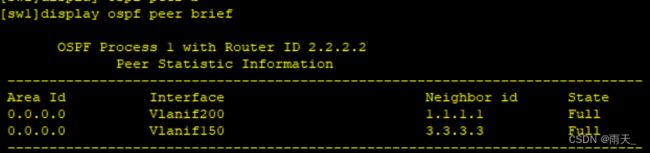

- 将AR2宣告到OSPF域中
[r2]ospf 1 router-id 4.4.4.4
[r2-ospf-1]a 0
[r2-ospf-1-area-0.0.0.0]network 14.1.1.2 0.0.0.0
[r2-ospf-1-area-0.0.0.0]network 4.4.4.4 0.0.0.0
(6)测试

