OSPF含特殊区域实验,MGRE构建和重发布
实验要求
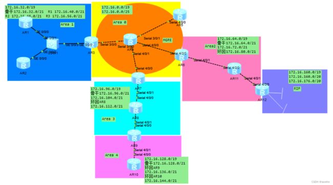
1.IP地址的划分
172.168.0.0/16划分6个网段 借3位
区域1
172.16.32.0/19划分4个子网
172.16.32.0/21 172.16.40.0/21 172.16.48.0/21 172.16.56.0/21
区域0
172.16.0.0/19 用作MGRE网段
区域2
172.16.64.0/19划分4个子网
172.16.64.0/21 172.16.72.0/21 172.16.80.0/21
备用 172.16.88.0/21
区域3
172.16.96.0/19划分4个子网
172.16.96.0/21 172.16.104.0/21 172.16.112.0/21
备用 172.168.120.0/21
区域4
172.16.128.0/19划分4个子网
172.16.128.0/21 172.16.136.0/21 172.16.144.0/21
备用 172.16.152.0/21
RIP
172.16.160.0/19划分2个子网
172.16.160.0/20 172.168.176.0/20
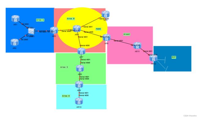
2.拓扑结构的搭建
3.IP地址的配置
以R1、R2、R3、R4举例
R1:
interface GigabitEthernet0/0/0
ip address 172.16.32.1 255.255.248.0
interface LoopBack0
ip address 172.16.40.1 255.255.248.0
R2:
interface GigabitEthernet0/0/0
ip address 172.16.32.2 255.255.248.0
interface LoopBack0
ip address 172.16.48.1 255.255.248.0
R3:
interface Serial3/0/0
ip address 11.1.1.1 255.255.255.0
interface GigabitEthernet0/0/0
ip address 172.16.32.3 255.255.248.0
interface LoopBack0
ip address 172.16.56.1 255.255.248.0
R4:
interface Serial3/0/0
ip address 11.1.1.2 255.255.255.0
interface Serial3/0/1
ip address 12.1.1.2 255.255.255.0
interface Serial4/0/0
ip address 13.1.1.2 255.255.255.0
interface Serial4/0/1
ip address 14.1.1.2 255.255.255.0
interface LoopBack0
ip address 1.1.1.1 255.255.255.0
4.缺省路由+NAT的配置
R3,R5,R6,R7添加缺省路由和NAT
以R3为例 ip route-static 0.0.0.0 0.0.0.0 11.1.1.2
![]()
添加nat
acl 2000
rule 1 permit any

interface Serial3/0/0
nat outbound 2000
5.R3—R5/6/7为MGRE环境,R3为中心站点
R3:
interface Tunnel0/0/0
ip address 172.16.0.1 255.255.255.128
tunnel-protocol gre p2mp
source 11.1.1.1
ospf network-type broadcast
nhrp entry multicast dynamic
nhrp network-id 100
R5:
 interface Tunnel0/0/0
 ip address 172.16.0.2 255.255.255.128
 tunnel-protocol gre p2mp
 source Serial4/0/0
 ospf network-type broadcast
 ospf dr-priority 0
 nhrp network-id 100
 nhrp entry 172.16.0.1 11.1.1.1 register
R6:
 interface Tunnel0/0/0
 ip address 172.16.0.3 255.255.255.128
 tunnel-protocol gre p2mp
 source Serial4/0/0
 ospf network-type broadcast
 ospf dr-priority 0
 nhrp network-id 100
 nhrp entry 172.16.0.1 11.1.1.1 register
R7:
 interface Tunnel0/0/0
 ip address 172.16.0.4 255.255.255.128
 tunnel-protocol gre p2mp
 source Serial4/0/0
 ospf network-type broadcast
 ospf dr-priority 0
 nhrp network-id 100
 nhrp entry 172.16.0.1 11.1.1.1 register
6.OSPF协议
以区域1为例
AR1:
ospf 1 router-id 1.1.1.1
area 0.0.0.1
network 172.16.0.0 0.0.255.255
AR2:
ospf 1 router-id 2.2.2.2
area 0.0.0.1
network 172.16.0.0 0.0.255.255
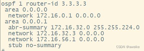
AR3:
ospf 1 router-id 3.3.3.3
 area 0.0.0.0
  network 172.16.0.1 0.0.0.0
 area 0.0.0.1
  abr-summary 172.16.32.0 255.255.224.0
  network 172.16.32.3 0.0.0.0
  network 172.16.56.1 0.0.0.0
7.重发布
在R9和R12上进行
R9:
创建ospf 2
ospf 2
 area 0.0.0.4
  network 172.16.128.1 0.0.0.0
  network 172.16.136.1 0.0.0.0
在ospf 1中进行重发步
import-route ospf 2
R12:
先起rip
rip 1
 version 2
 network 172.16.0.0
在ospf 1中重发步
import-route rip 1
8.域间路由汇总、域外路由汇总
R3:abr-summary 172.16.32.0 255.255.224.0
R6:abr-summary 172.16.64.0 255.255.224.0
R7:abr-summary 172.16.96.0 255.255.224.0
R9:asbr-summary 172.16.128.0 255.255.224.0
R12:asbr-summary 172.16.160.0 255.255.224.0
9.特殊区域
区域1为末梢区域
末梢区域—该区域拒绝4/5的LSA进入;由该区域连接骨干区域的ABR设备,向区域内发送一条3类的缺省路由;
完全末梢区域,在末梢区域的基础上进一步拒绝3类的LSA;仅保留一条3类的缺省路由;
先将该区域配置为末梢区域,然后仅在ABR上定义完全末梢即可;
区域2,3,4为nssa区域
同时存在ASBR
完全NSSA – 完全的非完全末梢区域;在普通NSSA的基础上,近一步拒绝3类的LSA,由ABR产生一条3类缺省先将该区域配置为普通的NSSA,然后仅在ABR上定义完全NSSA即可
10.空接口防环路由
在R3,R6,R7,R9,R12上设置
以R3为例
![]()
测试-实现全网可达
R1ping私网 R1pingR12的环回


