STM32之SPI和W25Q128
目录
SPI 介绍
SPI 物理架构
SPI 工作原理
SPI 工作模式
W25Q128 介绍
W25Q128 存储架构
W25Q128 常用指令
W25Q128 状态寄存器
W25Q128 常见操作流程
实验:使用 SPI 通讯读写 W25Q128 模块
硬件接线
cubeMX配置
w25q128_write_nocheck流程图
代码:
SPI 介绍
SPI 是什么?
SPI 是串行外设接口( Serial Peripheral Interface )的缩写,是一种高速的,全双工,同步的通信总
线,并且在芯片的管脚上只占用四根线,节约了芯片的管脚,同时为 PCB 的布局上节省空间,提
供方便,正是出于这种简单易用的特性,越来越多的芯片集成了这种通信协议,比如
AT91RM9200
SPI 物理架构
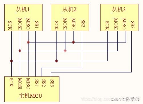
SPI 包含 4 条总线, SPI 总线包含 4 条总线,分别为 SS 、 SCK 、 MOSI 、 MISO 。它们的作用介绍如
下 :
(1) MISO – Master Input Slave Output ,主设备数据输入,从设备数据输出 (2) MOSI – Master
Output Slave Input ,主设备数据输出,从设备数据输入 (3) SCK – Serial Clock ,时钟信号,由主
设备产生 (4) CS – Chip Select ,片选信号,由主设备控制
SPI 工作原理
SPI 工作模式
时钟极性( CPOL ) :
没有数据传输时时钟线的空闲状态电平 0 : SCK 在空闲状态保持低电平 1 : SCK 在空闲状态保持高
电平
时钟相位( CPHA ) :
时钟线在第几个时钟边沿采样数据 0 : SCK 的第一(奇数)边沿进行数据位采样,数据在第一个时
钟边沿被锁存 1 : SCK 的第二(偶数)边沿进行数据位采样,数据在第二个时钟边沿被锁存
模式 0 和模式 3 最常用。
模式 0 时序图:
W25Q128 介绍
什么是 W25Q128 ?
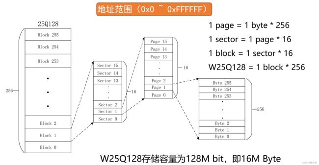
W25Q128 是华邦公司推出的一款 SPI 接口的 NOR Flash 芯片,其存储空间为 128 Mbit ,相当于
16M 字节。
Flash 是常用的用于储存数据的半导体器件,它具有容量大,可重复擦写、按 “ 扇区 / 块 ” 擦除、掉
电后数据可继续保存的特性。
Flash 是有一个物理特性:只能写 0 ,不能写 1 ,写 1 靠擦除。
W25Q128 全部指令非常多,但常用的如下几个指令:
写使能 (06H)
执行页写,扇区擦除,块擦除,片擦除,写状态寄存器等指令前,需要写使能。
拉低 CS 片选 → 发送 06H → 拉高 CS 片选
读状态寄存器( 05H )
拉低 CS 片选 → 发送 05H→ 返回 SR1 的值 → 拉高 CS 片选
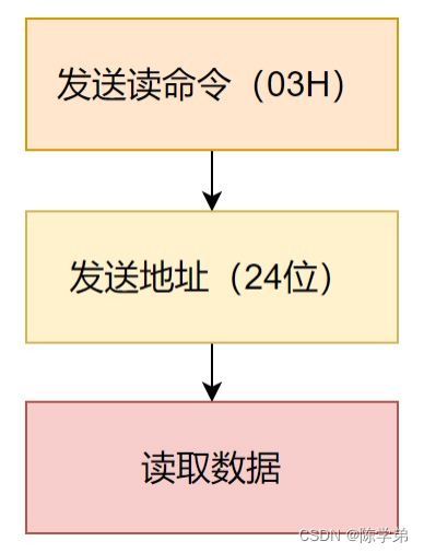
读时序( 03H )
拉低 CS 片选 → 发送 03H→ 发送 24 位地址 → 读取数据( 1~n ) → 拉高 CS 片选
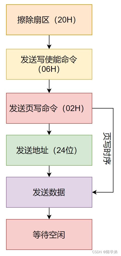
页写时序 (02H)
页写命令最多可以向 FLASH 传输 256 个字节的数据。
拉低 CS 片选 → 发送 02H→ 发送 24 位地址 → 发送数据( 1~n ) → 拉高 CS 片选
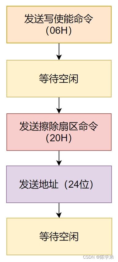
扇区擦除时序( 20H )
写入数据前,检查内存空间是否全部都是 0XFF ,不满足需擦除。
拉低 CS 片选 → 发送 20H→ 发送 24 位地址 → 拉高 CS 片选
W25Q128 状态寄存器
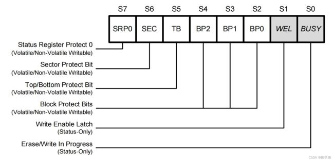
W25Q128 一共有 3 个状态寄存器,它们的作用是跟踪芯片的状态。
其中,状态寄存器 1 较为常用
BUSY :指示当前的状态, 0 表示空闲, 1 表示忙碌 WEL :写使能锁定,为 1 时,可以操作页 / 扇
区 / 块。为 0 时,写禁止。
W25Q128 常见操作流程
以下流程省略了拉低/拉高片选信号CS。
读操作:
擦除扇区:
写操作
实验:使用 SPI 通讯读写 W25Q128 模块
硬件接线
VCC -- 3.3V
CS -- PA4
CLK -- PA5
DO -- PA6
DI -- PA7
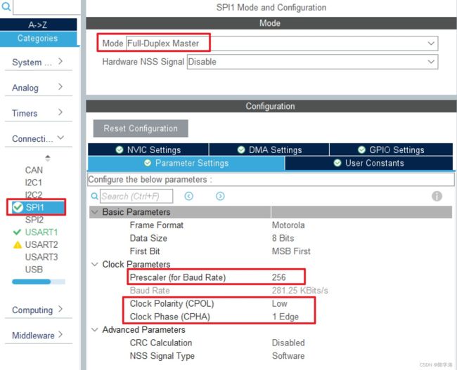
cubeMX配置
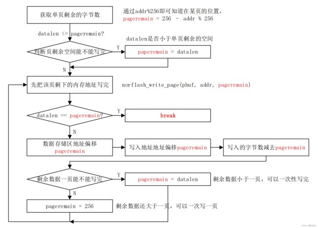
w25q128_write_nocheck流程图
代码:
spi.h
/* USER CODE BEGIN Header */
/**
  ******************************************************************************
  * @file    spi.h
  * @brief   This file contains all the function prototypes for
  *          the spi.c file
  ******************************************************************************
  * @attention
  *
  * Copyright (c) 2023 STMicroelectronics.
  * All rights reserved.
  *
  * This software is licensed under terms that can be found in the LICENSE file
  * in the root directory of this software component.
  * If no LICENSE file comes with this software, it is provided AS-IS.
  *
  ******************************************************************************
  */
/* USER CODE END Header */
/* Define to prevent recursive inclusion -------------------------------------*/
#ifndef __SPI_H__
#define __SPI_H__

#ifdef __cplusplus
extern "C" {
#endif

/* Includes ------------------------------------------------------------------*/
#include "main.h"

/* USER CODE BEGIN Includes */

/* USER CODE END Includes */

extern SPI_HandleTypeDef hspi1;

/* USER CODE BEGIN Private defines */

/* USER CODE END Private defines */

void MX_SPI1_Init(void);

/* USER CODE BEGIN Prototypes */
uint8_t spi1_read_write_byte(uint8_t data);
/* USER CODE END Prototypes */

#ifdef __cplusplus
}
#endif

#endif /* __SPI_H__ */
spi.c
/* USER CODE BEGIN Header */
/**
  ******************************************************************************
  * @file    spi.c
  * @brief   This file provides code for the configuration
  *          of the SPI instances.
  ******************************************************************************
  * @attention
  *
  * Copyright (c) 2023 STMicroelectronics.
  * All rights reserved.
  *
  * This software is licensed under terms that can be found in the LICENSE file
  * in the root directory of this software component.
  * If no LICENSE file comes with this software, it is provided AS-IS.
  *
  ******************************************************************************
  */
/* USER CODE END Header */
/* Includes ------------------------------------------------------------------*/
#include "spi.h"

/* USER CODE BEGIN 0 */

/* USER CODE END 0 */

SPI_HandleTypeDef hspi1;

/* SPI1 init function */
void MX_SPI1_Init(void)
{

  /* USER CODE BEGIN SPI1_Init 0 */

  /* USER CODE END SPI1_Init 0 */

  /* USER CODE BEGIN SPI1_Init 1 */

  /* USER CODE END SPI1_Init 1 */
  hspi1.Instance = SPI1;
  hspi1.Init.Mode = SPI_MODE_MASTER;
  hspi1.Init.Direction = SPI_DIRECTION_2LINES;
  hspi1.Init.DataSize = SPI_DATASIZE_8BIT;
  hspi1.Init.CLKPolarity = SPI_POLARITY_LOW;
  hspi1.Init.CLKPhase = SPI_PHASE_1EDGE;
  hspi1.Init.NSS = SPI_NSS_SOFT;
  hspi1.Init.BaudRatePrescaler = SPI_BAUDRATEPRESCALER_256;
  hspi1.Init.FirstBit = SPI_FIRSTBIT_MSB;
  hspi1.Init.TIMode = SPI_TIMODE_DISABLE;
  hspi1.Init.CRCCalculation = SPI_CRCCALCULATION_DISABLE;
  hspi1.Init.CRCPolynomial = 10;
  if (HAL_SPI_Init(&hspi1) != HAL_OK)
  {
    Error_Handler();
  }
  /* USER CODE BEGIN SPI1_Init 2 */

  /* USER CODE END SPI1_Init 2 */

}

void HAL_SPI_MspInit(SPI_HandleTypeDef* spiHandle)
{

  GPIO_InitTypeDef GPIO_InitStruct = {0};
  if(spiHandle->Instance==SPI1)
  {
  /* USER CODE BEGIN SPI1_MspInit 0 */

  /* USER CODE END SPI1_MspInit 0 */
    /* SPI1 clock enable */
    __HAL_RCC_SPI1_CLK_ENABLE();

    __HAL_RCC_GPIOA_CLK_ENABLE();
    /**SPI1 GPIO Configuration
    PA5     ------> SPI1_SCK
    PA6     ------> SPI1_MISO
    PA7     ------> SPI1_MOSI
    */
    GPIO_InitStruct.Pin = GPIO_PIN_5|GPIO_PIN_7;
    GPIO_InitStruct.Mode = GPIO_MODE_AF_PP;
    GPIO_InitStruct.Speed = GPIO_SPEED_FREQ_HIGH;
    HAL_GPIO_Init(GPIOA, &GPIO_InitStruct);

    GPIO_InitStruct.Pin = GPIO_PIN_6;
    GPIO_InitStruct.Mode = GPIO_MODE_INPUT;
    GPIO_InitStruct.Pull = GPIO_NOPULL;
    HAL_GPIO_Init(GPIOA, &GPIO_InitStruct);

  /* USER CODE BEGIN SPI1_MspInit 1 */

  /* USER CODE END SPI1_MspInit 1 */
  }
}

void HAL_SPI_MspDeInit(SPI_HandleTypeDef* spiHandle)
{

  if(spiHandle->Instance==SPI1)
  {
  /* USER CODE BEGIN SPI1_MspDeInit 0 */

  /* USER CODE END SPI1_MspDeInit 0 */
    /* Peripheral clock disable */
    __HAL_RCC_SPI1_CLK_DISABLE();

    /**SPI1 GPIO Configuration
    PA5     ------> SPI1_SCK
    PA6     ------> SPI1_MISO
    PA7     ------> SPI1_MOSI
    */
    HAL_GPIO_DeInit(GPIOA, GPIO_PIN_5|GPIO_PIN_6|GPIO_PIN_7);

  /* USER CODE BEGIN SPI1_MspDeInit 1 */

  /* USER CODE END SPI1_MspDeInit 1 */
  }
}

/* USER CODE BEGIN 1 */
uint8_t spi1_read_write_byte(uint8_t data)
{
    uint8_t rec_data = 0;

    HAL_SPI_TransmitReceive(&hspi1, &data, &rec_data, 1, 1000);

    return rec_data;
}
/* USER CODE END 1 */
main.c
/* USER CODE BEGIN Header */
/**
  ******************************************************************************
  * @file           : main.c
  * @brief          : Main program body
  ******************************************************************************
  * @attention
  *
  * Copyright (c) 2023 STMicroelectronics.
  * All rights reserved.
  *
  * This software is licensed under terms that can be found in the LICENSE file
  * in the root directory of this software component.
  * If no LICENSE file comes with this software, it is provided AS-IS.
  *
  ******************************************************************************
  */
/* USER CODE END Header */
/* Includes ------------------------------------------------------------------*/
#include "main.h"
#include "spi.h"
#include "usart.h"
#include "gpio.h"

/* Private includes ----------------------------------------------------------*/
/* USER CODE BEGIN Includes */
#include "stdio.h"
#include "string.h"
#include "w25q128.h"
/* USER CODE END Includes */

/* Private typedef -----------------------------------------------------------*/
/* USER CODE BEGIN PTD */

/* USER CODE END PTD */

/* Private define ------------------------------------------------------------*/
/* USER CODE BEGIN PD */
/* USER CODE END PD */

/* Private macro -------------------------------------------------------------*/
/* USER CODE BEGIN PM */
#define TEXT_SIZE 16
#define  FLASH_WriteAddress     0x00000
#define  FLASH_ReadAddress      FLASH_WriteAddress
/* USER CODE END PM */

/* Private variables ---------------------------------------------------------*/

/* USER CODE BEGIN PV */

/* USER CODE END PV */

/* Private function prototypes -----------------------------------------------*/
void SystemClock_Config(void);
/* USER CODE BEGIN PFP */

/* USER CODE END PFP */

/* Private user code ---------------------------------------------------------*/
/* USER CODE BEGIN 0 */

/* USER CODE END 0 */

/**
  * @brief  The application entry point.
  * @retval int
  */
int main(void)
{
  /* USER CODE BEGIN 1 */
	uint8_t datatemp[TEXT_SIZE];
  /* USER CODE END 1 */

  /* MCU Configuration--------------------------------------------------------*/

  /* Reset of all peripherals, Initializes the Flash interface and the Systick. */
  HAL_Init();

  /* USER CODE BEGIN Init */

  /* USER CODE END Init */

  /* Configure the system clock */
  SystemClock_Config();

  /* USER CODE BEGIN SysInit */

  /* USER CODE END SysInit */

  /* Initialize all configured peripherals */
  MX_GPIO_Init();
  MX_SPI1_Init();
  MX_USART1_UART_Init();
  /* USER CODE BEGIN 2 */
	w25q128_init();

	/* 写入测试数据 */
	sprintf((char *)datatemp, "liangxu shuai");
	w25q128_write(datatemp, FLASH_WriteAddress, TEXT_SIZE);
	printf("数据写入完成!\r\n");

	/* 读出测试数据 */
	memset(datatemp, 0, TEXT_SIZE);
	w25q128_read(datatemp, FLASH_ReadAddress, TEXT_SIZE);
	printf("读出数据:%s\r\n", datatemp);
  /* USER CODE END 2 */

  /* Infinite loop */
  /* USER CODE BEGIN WHILE */
  while (1)
  {
    /* USER CODE END WHILE */

    /* USER CODE BEGIN 3 */
  }
  /* USER CODE END 3 */
}

/**
  * @brief System Clock Configuration
  * @retval None
  */
void SystemClock_Config(void)
{
  RCC_OscInitTypeDef RCC_OscInitStruct = {0};
  RCC_ClkInitTypeDef RCC_ClkInitStruct = {0};

  /** Initializes the RCC Oscillators according to the specified parameters
  * in the RCC_OscInitTypeDef structure.
  */
  RCC_OscInitStruct.OscillatorType = RCC_OSCILLATORTYPE_HSE;
  RCC_OscInitStruct.HSEState = RCC_HSE_ON;
  RCC_OscInitStruct.HSEPredivValue = RCC_HSE_PREDIV_DIV1;
  RCC_OscInitStruct.HSIState = RCC_HSI_ON;
  RCC_OscInitStruct.PLL.PLLState = RCC_PLL_ON;
  RCC_OscInitStruct.PLL.PLLSource = RCC_PLLSOURCE_HSE;
  RCC_OscInitStruct.PLL.PLLMUL = RCC_PLL_MUL9;
  if (HAL_RCC_OscConfig(&RCC_OscInitStruct) != HAL_OK)
  {
    Error_Handler();
  }

  /** Initializes the CPU, AHB and APB buses clocks
  */
  RCC_ClkInitStruct.ClockType = RCC_CLOCKTYPE_HCLK|RCC_CLOCKTYPE_SYSCLK
                              |RCC_CLOCKTYPE_PCLK1|RCC_CLOCKTYPE_PCLK2;
  RCC_ClkInitStruct.SYSCLKSource = RCC_SYSCLKSOURCE_PLLCLK;
  RCC_ClkInitStruct.AHBCLKDivider = RCC_SYSCLK_DIV1;
  RCC_ClkInitStruct.APB1CLKDivider = RCC_HCLK_DIV2;
  RCC_ClkInitStruct.APB2CLKDivider = RCC_HCLK_DIV1;

  if (HAL_RCC_ClockConfig(&RCC_ClkInitStruct, FLASH_LATENCY_2) != HAL_OK)
  {
    Error_Handler();
  }
}

/* USER CODE BEGIN 4 */

/* USER CODE END 4 */

/**
  * @brief  This function is executed in case of error occurrence.
  * @retval None
  */
void Error_Handler(void)
{
  /* USER CODE BEGIN Error_Handler_Debug */
  /* User can add his own implementation to report the HAL error return state */
  __disable_irq();
  while (1)
  {
  }
  /* USER CODE END Error_Handler_Debug */
}

#ifdef  USE_FULL_ASSERT
/**
  * @brief  Reports the name of the source file and the source line number
  *         where the assert_param error has occurred.
  * @param  file: pointer to the source file name
  * @param  line: assert_param error line source number
  * @retval None
  */
void assert_failed(uint8_t *file, uint32_t line)
{
  /* USER CODE BEGIN 6 */
  /* User can add his own implementation to report the file name and line number,
     ex: printf("Wrong parameters value: file %s on line %d\r\n", file, line) */
  /* USER CODE END 6 */
}
#endif /* USE_FULL_ASSERT */
