STM32单片机(三)第四节:GPIO输入练习(按键控制LED、光敏传感器控制蜂鸣器)
❤️ 专栏简介:本专栏记录了从零学习单片机的过程,其中包括51单片机和STM32单片机两部分;建议先学习51单片机,其是STM32等高级单片机的基础;这样再学习STM32时才能融会贯通。
☀️ 专栏适用人群 :适用于想要从零基础开始学习入门单片机,且有一定C语言基础的的童鞋。
专栏目标:实现从零基础入门51单片机和STM32单片机,力求在玩好单片机的同时,能够了解一些计算机的基本概念,了解电路及其元器件的基本理论等。⭐️ 专栏主要内容: 主要学习STM32单片机的功能、各个模块、单片机的外设、驱动等,最终玩好单片机和单片机的外设,全程手敲代码,实现我们所要实现的功能。
专栏说明 :如果文章知识点有错误的地方,欢迎大家随时在文章下面评论,我会第一时间改正。让我们一起学习,一起进步。
专栏主页:http://t.csdn.cn/HCD8v
本学习过程参考:https://space.bilibili.com/383400717
STM3单片机安装软件、各种资料以及源码的路径:
链接:https://pan.baidu.com/s/1snD0uuTfMhchFqOMWvAiHA?pwd=asdf#list/path=%2F
提取码:asdf
链接里压缩包的解压密码:32
本大节主要学习GPIO通用输入输出口,包含两部分,第一小节主要学习GPIO的输出,第二小节是写三个简单的程序进行练习,分别是LED闪烁、LED流水灯、蜂鸣器等;第三小节是学习GPIO输入,第四小节是写两个简单的程序进行练习,分别是按键控制LED和光敏传感器控制蜂鸣器;
本小节主要是对上一节学习的GPIO输入知识进行实战练习,编写两个程序进行练习,分别实现按键控制LED和光敏传感器控制蜂鸣器等,并附上程序源码;
文章目录
- 一、本节目标
-
- 1.1 按键控制LED
- 1.2 光敏传感器控制蜂鸣器
- 二、按键控制LED
-
- 2.1 接线图
- 2.2 代码实现
- 三、光敏传感器控制蜂鸣器
-
- 3.1 接线图
- 3.2 代码实现
一、本节目标
1.1 按键控制LED
1.2 光敏传感器控制蜂鸣器
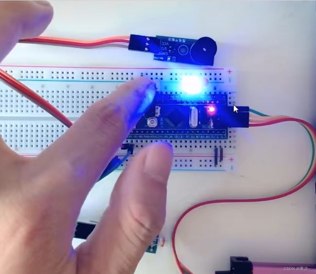
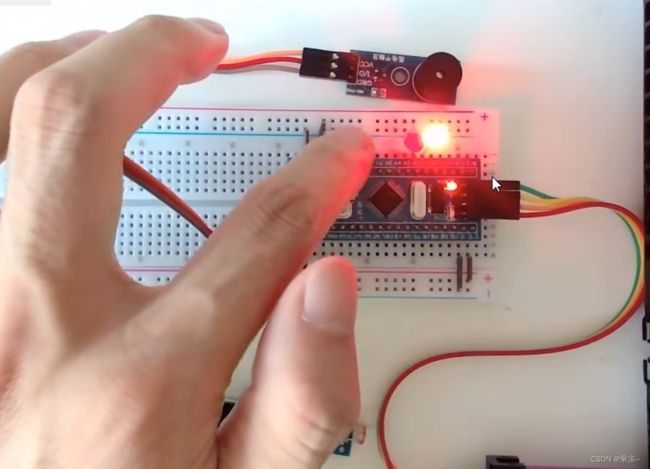
面包板上连接蜂鸣器模块和光敏电阻传感器模块,当用手挡住光敏电阻,光线变暗时,蜂鸣器就会响;把手拿开,光线变亮时,蜂鸣器就停止。
二、按键控制LED
2.1 接线图

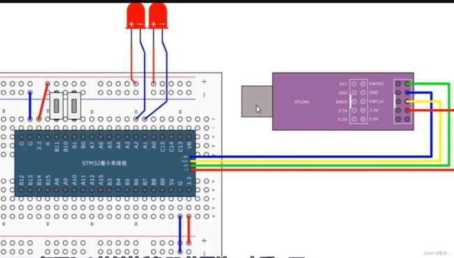
接线图入上图所示,接了两个按键和两个LED,两个按键分别接在PB1和PB11两个口上,按键一段接GPIO口,另一端接GND;两个LED分别接在了PA1和PA2两个口上,LED一段接GPIO口,另一端接VCC,就是低电平点亮的接法;
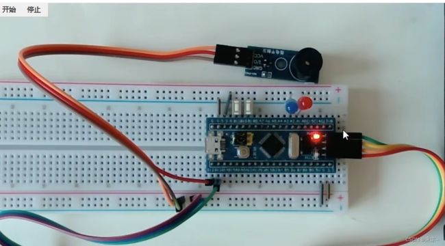
硬件接好好如上图所示;
2.2 代码实现
代码路径:STM32入门教程资料\程序源码\STM32Project\3-4 按键控制LED\User
具体代码:
#include "stm32f10x.h"                  // Device header
#include "Delay.h"
#include "LED.h"
#include "Key.h"

uint8_t KeyNum;

int main(void)
{
	LED_Init();
	Key_Init();

	while (1)
	{
		KeyNum = Key_GetNum();
		if (KeyNum == 1)
		{
			LED1_Turn();
		}
		if (KeyNum == 2)
		{
			LED2_Turn();
		}
	}
}
key.c://主要负责按键的相关功能
#include "stm32f10x.h"                  // Device header
#include "Delay.h"

void Key_Init(void)
{
	RCC_APB2PeriphClockCmd(RCC_APB2Periph_GPIOB, ENABLE);

	GPIO_InitTypeDef GPIO_InitStructure;
	GPIO_InitStructure.GPIO_Mode = GPIO_Mode_IPU;
	GPIO_InitStructure.GPIO_Pin = GPIO_Pin_1 | GPIO_Pin_11;
	GPIO_InitStructure.GPIO_Speed = GPIO_Speed_50MHz;
	GPIO_Init(GPIOB, &GPIO_InitStructure);
}

uint8_t Key_GetNum(void)
{
	uint8_t KeyNum = 0;
	if (GPIO_ReadInputDataBit(GPIOB, GPIO_Pin_1) == 0)
	{
		Delay_ms(20);
		while (GPIO_ReadInputDataBit(GPIOB, GPIO_Pin_1) == 0);
		Delay_ms(20);
		KeyNum = 1;
	}
	if (GPIO_ReadInputDataBit(GPIOB, GPIO_Pin_11) == 0)
	{
		Delay_ms(20);
		while (GPIO_ReadInputDataBit(GPIOB, GPIO_Pin_11) == 0);
		Delay_ms(20);
		KeyNum = 2;
	}

	return KeyNum;
}
LED.c://主要负责LEC相关操作
#include "stm32f10x.h"                  // Device header

void LED_Init(void)
{
	RCC_APB2PeriphClockCmd(RCC_APB2Periph_GPIOA, ENABLE);

	GPIO_InitTypeDef GPIO_InitStructure;
	GPIO_InitStructure.GPIO_Mode = GPIO_Mode_Out_PP;
	GPIO_InitStructure.GPIO_Pin = GPIO_Pin_1 | GPIO_Pin_2;
	GPIO_InitStructure.GPIO_Speed = GPIO_Speed_50MHz;
	GPIO_Init(GPIOA, &GPIO_InitStructure);

	GPIO_SetBits(GPIOA, GPIO_Pin_1 | GPIO_Pin_2);
}

void LED1_ON(void)
{
	GPIO_ResetBits(GPIOA, GPIO_Pin_1);
}

void LED1_OFF(void)
{
	GPIO_SetBits(GPIOA, GPIO_Pin_1);
}

void LED1_Turn(void)
{
	if (GPIO_ReadOutputDataBit(GPIOA, GPIO_Pin_1) == 0)
	{
		GPIO_SetBits(GPIOA, GPIO_Pin_1);
	}
	else
	{
		GPIO_ResetBits(GPIOA, GPIO_Pin_1);
	}
}

void LED2_ON(void)
{
	GPIO_ResetBits(GPIOA, GPIO_Pin_2);
}

void LED2_OFF(void)
{
	GPIO_SetBits(GPIOA, GPIO_Pin_2);
}

void LED2_Turn(void)
{
	if (GPIO_ReadOutputDataBit(GPIOA, GPIO_Pin_2) == 0)
	{
		GPIO_SetBits(GPIOA, GPIO_Pin_2);
	}
	else
	{
		GPIO_ResetBits(GPIOA, GPIO_Pin_2);
	}
}
三、光敏传感器控制蜂鸣器
3.1 接线图
蜂鸣器:
VCC接电源正,GND接电源负,控制脚接PB12;
光敏传感器:
VCC接电源正,GND接电源负,DO输出脚接PB13;
如下图所示:

上电,可以看到光敏传感器的灯亮了;当我们遮住光线时,输出指示灯灭,代表输出高电平;松手时,输出指示灯亮,代表输出低电平;
3.2 代码实现
代码路径:STM32入门教程资料\程序源码\STM32Project\3-5 光敏传感器控制蜂鸣器\User
具体代码:
#include "stm32f10x.h"                  // Device header
#include "Delay.h"
#include "Buzzer.h"
#include "LightSensor.h"

int main(void)
{
	Buzzer_Init();
	LightSensor_Init();

	while (1)
	{
		if (LightSensor_Get() == 1)
		{
			Buzzer_ON();
		}
		else
		{
			Buzzer_OFF();
		}
	}
}
LightSensor.c:
#include "stm32f10x.h"                  // Device header

void LightSensor_Init(void)
{
	RCC_APB2PeriphClockCmd(RCC_APB2Periph_GPIOB, ENABLE);

	GPIO_InitTypeDef GPIO_InitStructure;
	GPIO_InitStructure.GPIO_Mode = GPIO_Mode_IPU;
	GPIO_InitStructure.GPIO_Pin = GPIO_Pin_13;
	GPIO_InitStructure.GPIO_Speed = GPIO_Speed_50MHz;
	GPIO_Init(GPIOB, &GPIO_InitStructure);
}

uint8_t LightSensor_Get(void)
{
	return GPIO_ReadInputDataBit(GPIOB, GPIO_Pin_13);
}
Buzzer.c://蜂鸣器相关功能实现
#include "stm32f10x.h"                  // Device header

void Buzzer_Init(void)
{
	RCC_APB2PeriphClockCmd(RCC_APB2Periph_GPIOB, ENABLE);

	GPIO_InitTypeDef GPIO_InitStructure;
	GPIO_InitStructure.GPIO_Mode = GPIO_Mode_Out_PP;
	GPIO_InitStructure.GPIO_Pin = GPIO_Pin_12;
	GPIO_InitStructure.GPIO_Speed = GPIO_Speed_50MHz;
	GPIO_Init(GPIOB, &GPIO_InitStructure);

	GPIO_SetBits(GPIOB, GPIO_Pin_12);
}

void Buzzer_ON(void)
{
	GPIO_ResetBits(GPIOB, GPIO_Pin_12);
}

void Buzzer_OFF(void)
{
	GPIO_SetBits(GPIOB, GPIO_Pin_12);
}

void Buzzer_Turn(void)
{
	if (GPIO_ReadOutputDataBit(GPIOB, GPIO_Pin_12) == 0)
	{
		GPIO_SetBits(GPIOB, GPIO_Pin_12);
	}
	else
	{
		GPIO_ResetBits(GPIOB, GPIO_Pin_12);
	}
}
LightSensor.c://负责光敏电阻功能实现
#include "stm32f10x.h"                  // Device header

void LightSensor_Init(void)
{
	RCC_APB2PeriphClockCmd(RCC_APB2Periph_GPIOB, ENABLE);

	GPIO_InitTypeDef GPIO_InitStructure;
	GPIO_InitStructure.GPIO_Mode = GPIO_Mode_IPU;
	GPIO_InitStructure.GPIO_Pin = GPIO_Pin_13;
	GPIO_InitStructure.GPIO_Speed = GPIO_Speed_50MHz;
	GPIO_Init(GPIOB, &GPIO_InitStructure);
}

uint8_t LightSensor_Get(void)
{
	return GPIO_ReadInputDataBit(GPIOB, GPIO_Pin_13);
}


