第12课【DMA 直接数据访问】直接数据访问 效率 数据总线冲突 通道 仲裁器
目录
- 简介
- 功能框图
-
- 请求
- 通道
- 仲裁器
- 使用配置
-
- 传输方向
- 数据量
- 传输模式
- 实例分析
-
- 存储器间传输
- 存储器到外设
简介
DMA(Direct Memory Access 直接内存访问)指的是STM32中的一个外设。它可以在无需CPU介入的情况下,实现外设和存储器之间或存储器与存储器之间的数据传输,这里的存储器指的是SRAM或者是Flash。在进行一些大批量的,或者是周期性重复的数据转移工作时,通常都会使用到DMA,这使得CPU可以腾出时间完成其他更具意义的任务,从而提高处理效率,在这点上,DMA和GPU的存在意义类似,都是用于处理专门的需求或者数据而存在的
STM32的DMA的控制器包含了两个DMA:DMA1和DMA2,其中DMA1拥有7个通道(可以理解为数据传输通道),DMA2拥有5各通道。DMA2在大容量类型或互联网类型STM32产品上才会搭载
STM32上的DMA外设有以下特点:
- 12个通道(DMA1有7个,DMA2有5个)都可独立配置
- 低、中、高、最高四种通道优先级可选
- SRAM,Flash,AHB/APB1/APB2总线上的基本所有外设都支持DMA
功能框图
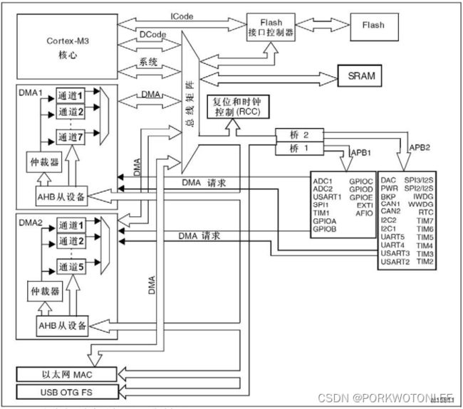
STM32的DMA外设同其他外设一样,也是独立于Cortex内核的存在,其可以大致分为三部分:请求,通道,仲裁器,功能框图如下:
请求
其他外设如果需要使用DMA功能,需要向DMA发送请求,DMA收到请求后,会根据情况给发起请求的外设一个应答信号,只有当请求的外设收到应答信号时,才会启动DMA传输功能
通道
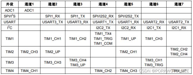
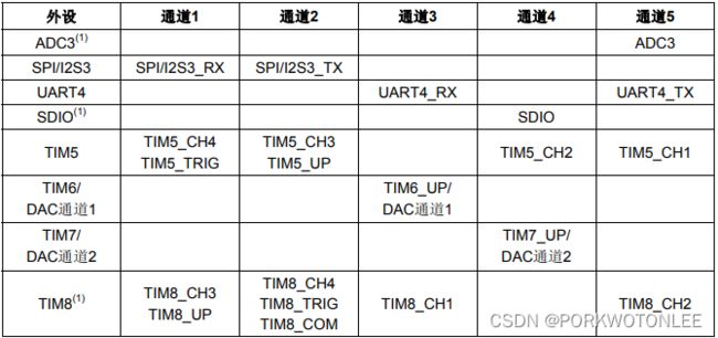
通道指代的是数据传输通道,DMA1有7条通道,DMA2有5条通道,12条通道都可以独立编程控制,并且每条通道对应了不同的外设,具体对应如下图:
可以看到,每个通道可以对应多个外设。但是同一时间,一个通道只能被一个外设使用,需要多个外设同时使用同一个通道时,开发者需要注意规划外设DMA通道时序,以确保通道带宽得到有效且正确的分配
DMA传输的实现机制以及拓展思考
DMA传输实际上还是需要同Cortex内核共享系统数据总线来实现的,这就意味着在DMA传输进行时,CPU依旧是需要等待的,既然需要等待那么如何提高访问效率呢。为此,STM开发者是这么设计的,当DMA外设和内核同时访问同一个设备时,DMA外设会暂停内核访问总线的若干个周期,同时总线总裁器执行循环调度,保证内核能至少获得总线一半的带宽,
仲裁器
类似于多个外设同时使用一个通道的场景,DMA传输在同一时刻只能对一个通道进行数据传输操作,当DMA控制器同时接收到来自多个通道的数据传输请求时,会通过优先级进行仲裁,优先级分为两种:软件优先级和硬件优先级
- 软件优先级:可以通过DMA_CCR寄存器对单独某个通道进行优先级配置,分别有四种:低,中,高,最高。高优先级通道的数据传输请求会被优先处理
- 硬件优先级:如果某两个通道的软件优先级配置一致,那么会根据通道固定的硬件优先级进行比较,硬件优先级数字越小,优先级越高
使用配置
DMA外设的数据传输配置,主要是需要对数据的元数据(即描述数据用的数据)进行配置:包括传输方向,数据量,传输模式
传输方向
DMA传输数据的方向分为三种:外设到存储器,存储器到外设,存储器到存储器。三种方向主要通过以下寄存器中的位来配置:
- DMA_CCR寄存器的DIR位:配置DMA数据的传输方向,DIR位置1时,从存储器读取数据,写入到外设,即存储器->外设;DIR位清0时,从外设读取数据,写入到存储器中,即外设->存储器;当使用存储器到存储器模式时,还需要将寄存器中的MEM2MEM位置1。
- DMA_CPARx(x = 1~7)寄存器:配置外设的地址
- DMA_CMARx(x = 1…7)寄存器:配置存储器的地址
具体举例三种情况:
- 外设到存储器:例如通过DMA外设将串口外设的数据传输到SRAM中,首先要配置DMA_CPARx
寄存器中的外设地址,也就是串口外设的数据寄存器地址,之后再配置DMA_CMARx
寄存器中的存储器地址,即代码中的临时缓存变量地址,临时变量会存储于SRAM中,最后将DMA_CCR寄存器中的DIR位清0,表示传输方向为:外设->存储器 - 存储器到外设:与上一个例子类似,只不过传输方向需要改为存储器->外设,需要将DMA_CCR寄存器中的DIR位置1
- 存储器到存储器:存储器到存储器同以上两个例子有些许不同,例如将Flash的数据传输到SRAM(Flash中的数据只读),那么可以将Flash的访问地址当作外设地址,配置到DMA_CPARx寄存器中;将临时变量的地址当作存储器地址,配置到DMA_CMARx寄存器中;而此模式下传输方向仅支持配置为Flash到SRAM,DMA_CCR寄存器的DIR位无需进行配置;同时需要将DMA_CCR寄存器中的MEM2MEM位置
数据量
数据量的配置包括了,数据量大小,单个数据的宽度,以及数据指针增量模式。主要通过以下寄存器中的位来配置:
- DMA_CNDTRx(x = 1…7)寄存器:用于显示剩余待传输的数据的量。最小值为0,此时无论如何都不会发生数据传输,最大值为65535(无符号32位寄存器),最多一次能传输65536Bytes的数据。每传输1Byte数据,此寄存器会自减1。如果此寄存器的值自减到0,那么会根据是否有配置重载数据,进行寄存器值重新装载
- DMA_CCRx(x = 1…7)寄存器的PSIZE位[1:0]/MSIZE位[1:0]:用于配置外设/存储器数据宽度。PSIZE位[1:0]配置外设数据宽度,MSIZE位[1:0]配置存储器数据宽度,可以是8/16/32位。但是要确保两者的数据宽度是一致的,才能进行数据传输
- DMA_CCRx(x = 1…7)寄存器的PINC位/MINC位:用于配置数据传输时的数据指针增量模式,外设的地址指针由DMA_CCRx的PINC位配置,PINC位置1时,每完成一次数据传输,外设的数据指针会自增1,PINC位清0时,每完成一次数据传输,外设的数据指针保持不变,存储器的地址指针由MINC位配置,配置方法和PINC位类似。是否需要启用指针增量模式,由开发者来决定
传输模式
传输模式分为两种:单次传输和循环传输。顾名思义,单次传输进行一次传输,而循环传输会一直不间断的进行单次传输,每轮单次传输完成后,都会重新按照初始配置重新进行传输。传输模式由DMA_CCRx(x = 1…7)寄存器的CIRC位控制,CIRC位置1时,执行循环传输操作,CIRC位清0时,执行单次传输操作
对于两种传输的传输状态,包括传输过半,传输完成,传输出错都有相应的标志位去查询,同时也可以启用中断,通过中断去对特定指定状态执行对应操作
实例分析
以下内容基于STM32F103VET野火指南者开发板,分别实现两个功能:
- (存储器间传输)通过DMA将Flash数据复制到SRAM中,对比两份数据,查看DMA传输是否成功
- (存储器到外设)通过DMA将SRAM数据复制到串口外设的数据寄存器中,并循环发送到PC端,查看是否准确发送。同时主程序中运行LED闪烁实验,以验证DMA传输不影响CPU进行其他活动
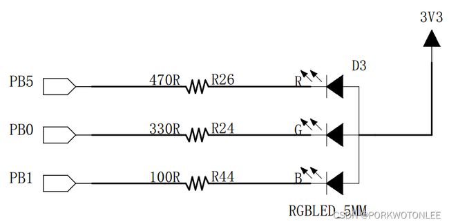
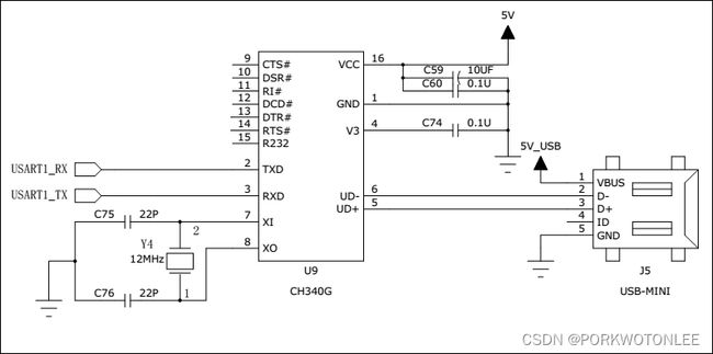
会使用到开发板的LED灯模块以及USB串口模块(实际上是USART模块+CH340G芯片),原理图分别如下:
首先,需要解析标准库提供的DMA初始化结构体,以及相关操作函数:
/**
  * @brief  DMA Init structure definition
  */

typedef struct
{
  uint32_t DMA_PeripheralBaseAddr; /*!< Specifies the peripheral base address for DMAy Channelx. */

  uint32_t DMA_MemoryBaseAddr;     /*!< Specifies the memory base address for DMAy Channelx. */

  uint32_t DMA_DIR;                /*!< Specifies if the peripheral is the source or destination.
                                        This parameter can be a value of @ref DMA_data_transfer_direction */

  uint32_t DMA_BufferSize;         /*!< Specifies the buffer size, in data unit, of the specified Channel.
                                        The data unit is equal to the configuration set in DMA_PeripheralDataSize
                                        or DMA_MemoryDataSize members depending in the transfer direction. */

  uint32_t DMA_PeripheralInc;      /*!< Specifies whether the Peripheral address register is incremented or not.
                                        This parameter can be a value of @ref DMA_peripheral_incremented_mode */

  uint32_t DMA_MemoryInc;          /*!< Specifies whether the memory address register is incremented or not.
                                        This parameter can be a value of @ref DMA_memory_incremented_mode */

  uint32_t DMA_PeripheralDataSize; /*!< Specifies the Peripheral data width.
                                        This parameter can be a value of @ref DMA_peripheral_data_size */

  uint32_t DMA_MemoryDataSize;     /*!< Specifies the Memory data width.
                                        This parameter can be a value of @ref DMA_memory_data_size */

  uint32_t DMA_Mode;               /*!< Specifies the operation mode of the DMAy Channelx.
                                        This parameter can be a value of @ref DMA_circular_normal_mode.
                                        @note: The circular buffer mode cannot be used if the memory-to-memory
                                              data transfer is configured on the selected Channel */

  uint32_t DMA_Priority;           /*!< Specifies the software priority for the DMAy Channelx.
                                        This parameter can be a value of @ref DMA_priority_level */

  uint32_t DMA_M2M;                /*!< Specifies if the DMAy Channelx will be used in memory-to-memory transfer.
                                        This parameter can be a value of @ref DMA_memory_to_memory */
}DMA_InitTypeDef;
其中结构体成员的含义分别如下:
- DMA_PeripheralBaseAddr:外设地址
- DMA_MemoryBaseAddr:存储器地址
- DMA_DIR:数据传输方向。可以是外设->存储器,也可以是存储器->外设
- DMA_BufferSize:传输数据量的大小。最小为0Byte,最大为65536Bytes
- DMA_PeripheralInc:外设地址的增量模式。由开发者选择是否使用
- DMA_MemoryInc:存储器地址的增量模式。由开发者选择是否使用
- DMA_PeripheralDataSize:外设地址可以获取到的单次传输的数据大小。可以是8/16/32bits
- DMA_MemoryDataSize:存储器地址可以获取到的单次传输的数据大小。可以是8/16/32bits
- DMA_Mode:传输模式。分为单次传输和循环传输
- DMA_Priority:通道优先级。分为低、中、高、最高四种
- DMA_M2M:是否开启存储器到存储器模式。只有使用存储器间传输时会开启
存储器间传输
此功能的实现思路为:
- 初始化Flash中的源数据,以及SRAM中的目标数据
- 初始化LED灯用GPIO口
- 初始化DMA传输参数
- 启动DMA传输
- 对比源数据与目标数据,将结果通过LED灯颜色展示出来
分别建立DMA相关板级支持文件bsp_dma.h,bsp_dma.c,内容分别如下:
- bsp_dma.h:
#ifndef __BSP_DMA_H__
#define __BSP_DMA_H__
#include - bsp_dma.c:
#include "bsp_dma.h"
#include "stm32f10x.h"
#include "stm32f10x_dma.h"
#include "stm32f10x_rcc.h"
#include 通过板级支持包代码实现需求:
#include "userapp.h"
#include "bsp_dma.h"
#include "bsp_clkconfig.h"
#include "bsp_led.h"
#include "stm32f10x.h"
#include "stm32f10x_dma.h"
#include 存储器到外设
此功能的实现思路为和存储器间的样例没有很大不同,但是要注意以下几点:
- 需要初始化串口用GPIO口以及串口模块
- 不需要开启DMA传输的M2M模式
- 将Flash当作外设来处理
- 需要额外配置USART的DMA控制发送功能,此功能仅DMA 通道4支持
分别建立DMA相关板级支持文件bsp_dma_uart.h,bsp_dma_uart.c,内容分别如下:
- bsp_dma_uart.h:
#ifndef __BSP_DMA_UART_H__
#define __BSP_DMA_UART_H__

#include "stm32f10x_usart.h"

#define UART_DR_ADDR         (USART1_BASE + 0x04)

// DMA
#define UART_DMA_CLK              RCC_AHBPeriph_DMA1
#define UART_DMA_CHANNEL          DMA1_Channel4 // channel 4 support only
#define UART_DMA_BUFFER_SIZE      64

extern uint8_t aSRC_Buffer[UART_DMA_BUFFER_SIZE];

void UART_DMA_Config(void);

#endif
- bsp_dma_uart.c:
#include "bsp_dma_uart.h"
#include "bsp_uart.h"
#include "stm32f10x.h"
#include "stm32f10x_dma.h"
#include "stm32f10x_gpio.h"
#include "stm32f10x_rcc.h"
#include "stm32f10x_usart.h"
#include 通过板级支持包代码实现需求:
#include "userapp.h"
#include "bsp_clkconfig.h"
#include "bsp_uart.h"
#include "bsp_dma_uart.h"
#include "bsp_led.h"
#include "stm32f10x.h"
#include "stm32f10x_dma.h"
#include "stm32f10x_usart.h"
#include 示例代码已上传Github:Sinuxtm32
