检测PPG信号的心跳
基于大佬的代码。
PPG信号靠心率 (HR) 进行估计,主要取决于收缩压峰值检测的准确性。与 ECG 不同,PPG 信号形式简单和特定点 少。低振幅 PPG 信号更容易受到噪声污染和其他不良影响的影响,例如baseline drift和wandering。这是由于信号强度与噪声功率相当。在这种情况下,PPG 记录可能会出现一些波纹,如果检测算法不够robust,这些波纹可能会被错误地标记为峰值。
有人认为应该从信号采集和调节阶段解决 PPG 波幅度的降低问题,但这种降低也可以在受伤后(例如,当患者经历手术过程的第一个手术切口时)或呼吸暂停期间观察到,作为交感神经张力增加引起的外周血管收缩的结果。
PPG(Photoplethysmography)光电容积脉搏波描记法
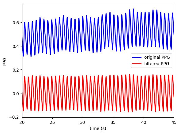
导入数据后,用signal.butter创建butterband过滤器
# Specify cutoff in Hertz
lpf_cutoff = 0.7
hpf_cutoff = 10

#Create a Butterworth filter
sos_ppg = signal.butter(10,
                    [lpf_cutoff, hpf_cutoff],
                    btype = 'bp',
                    analog = False,
                    output = 'sos',
                    fs = segment_data.fs)

w, h = signal.sosfreqz(sos_ppg,
                   2000,
                   fs = fs)
过滤出的信号和原信号一起塞进sosfiltfilt获得过滤之后的信号
ppg_filt = signal.sosfiltfilt(sos_ppg, ppg)
对信号求导
# Calculate first derivative
d1ppg = signal.savgol_filter(ppg_filt, 9, 5, deriv=1)

# Calculate second derivative
d2ppg = signal.savgol_filter(d1ppg, 9, 5, deriv=1)
对于PPG信号,这篇文章
可以对PPG信号求导,一阶导数 PPG (VPG) 和二阶导数 PPG (APG) 对应的分别是velocity plethysmogram 和acceleration plethysmogram。PPG信号的峰值对病理的研究很重要,导数波形能表现出更多的重要波峰。
光电体积描记图波形带有四个主要基准点,即起始点(脚)、收缩峰、重搏切迹和舒张峰。这显示在下图,表示收缩期脉搏的开始,此时含氧血液在测量部位流动。收缩期峰值是收缩期射血开始后的最大峰值。从开始到收缩的上升沿表示动脉中压力的增加,如动脉血压 (ABP) 波形中所测量的那样。重搏切迹和舒张峰是外周的波反射,受动脉硬度或血管阻力和顺应性的影响 。如果发作与收缩期射血的开始有关,那么舒张期表示主动脉瓣关闭时射血的结束。随着人们开始衰老,切迹和舒张压往往会在信号中消失。(一段机翻)
PPG, VPG, and APG的基准点:
PPG: onset, systolic, notch, and diastolic peaks
VPG: u, v, and w peaks
速度体积描记图反映时间序列振幅变化的速度,包含收缩期最大斜率点(u-peak)、舒张期最小斜率点(v-peak)和舒张期最大斜率点(w-peak)三个突出的峰,Li 等人使用了 u 峰前后的零交叉点。寻找起搏和收缩峰。w-peak 之后的零交叉点相当于舒张期峰值。它是 w-peak 和 u-peak 之间的变化(从收缩到舒张峰值所用的时间),用于测量动脉的硬度指数. 但也有振幅w不超过零的情况,舒张期出现多个低振幅正波。这可能与原始 PPG 信号上的电噪声、直流偏移或滤波偏移有关。因此,很少使用这种衍生标记。(一段机翻)
*Li:Li BN, Dong MC, Vai MI. On an automatic delineator for arterial blood pressure waveforms. Biomed Signal Process Control. (2010) 5:76–81. 10.1016/j.bspc.2009.06.002
APG: a, b, c, d, and e peaks
与 VPG 相比,APG 的分析更为频繁。APG波形中有a、b、c、d四个收缩期波和一个舒张早期e波。这里的一个关键标记是 e-peak 相当于dicrotic notch。然后,可以通过 notch 之后的第一个局部最大值来确定舒张期峰值。然而,影响波形的老化和其他病理因素会使通过这种方法检测舒张峰变得复杂。Millasseau 等人提出了另一种通过检查 VPG 来估计舒张期切迹的方法。(一段机翻)
*Millasseau : Millasseau SC, Kelly RP, Ritter JM, Chowienczyk PJ. Determination of age-related increases in large artery stiffness by digital pulse contour analysis. Clin Sci. (2002) 103:371–7. 10.1042/cs1030371

在这个数据上表示为:

PPG信号的心跳检测
预处理:去除信号趋势,bandpass,sosfilt过滤器
应用bandpass主要是去除高频噪声(如运动伪影)和低频噪声(如基线漂移),这里用了butterworth,是一种特殊的bandpass
    x_d = signal.detrend(x)
    sos = signal.butter(10, [0.5, 10], btype = 'bp', analog = False, output = 'sos', fs = fs)
    x_f = signal.sosfiltfilt(sos, x_d)
心跳检测的几种适用算法:
1: HeartPy
2: 2nd derivative maxima
3: Systolic upslopes
4: Delineator
5: qppg
6: Bishop
HeartPy
HeartPy 有自己的库可以用,github链接
可以直接pip install,
2nd derivative maxima
Systolic Peak Detection in Acceleration Photoplethysmograms Measured from Emergency Responders in Tropical Conditions里描述:
PPG信号的三种收缩峰检测方法:
- Local Minima and Maxima 计算局部最大最小值
具体操作就是在ppg信号之后应用带通滤波器bandpass filter 以增强最大值(峰值)搜索期间的信号。再接一个阈值过滤(比如0.1),如果一个点具有最大值并且如果先前时间步长的值低于阈值,

- First Derivative with Adaptive Thresholds 具有自适应阈值的一阶导数
ppg信号后用一个低通滤波器,再将过滤后的 PPG 波形分割成多个相等的部分(即,每个部分具有相同的波形样本),然后将选择窗口(持续时间为 2 秒)应用于每个部分的开始。在这些窗口内,振幅和脉搏率被估计并平均为初始阈值。然后,描绘器 delineator 以逐拍的方式搜索 PPG 波形及其导数中的拐点对 pairs of inflection 和零交叉点 zero-crossing points 。最后,在 beat evaluation 阶段,描绘器会重新检查 PPG 波形,并根据阈值估计阶段确定的振幅和间隔阈值来识别候选起始点和收缩峰。

- Slope Sum function with An Adaptive Threshold 具有自适应阈值的斜率和函数
斜率的定义:
W是分析窗口的长度,N是ppg样本总数,Δy[k]是y[n]-y[n-1],y是经过滤波的PPG信号

阈值计算阶段是自适应的。先将自适应阈值初始化为信号均值的三倍 Z[1 : 8fs], 记录前八秒的平均值,如下所示:
- Event-Related Moving Averages with Dynamic Threshold 具有动态阈值的事件相关移动平均线
该方法包括三个主要阶段:预处理(bandpass filtering and squaring)、特征提取(generating potential blocks using two moving averages)和分类(thresholding)。
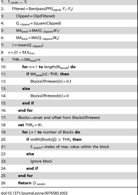
算法伪代码:
实施zero-phase second-order的 Butterworth filter,bandpass 0.5–8 Hz,用于以消除对收缩峰无贡献的基线漂移 baseline wander 和高频,应用于 PPG 信号的滤波器的输出将产生一个滤波信号S[n] 然后,通过将信号裁剪在零以上来限幅输出将产生信号Z[n]。
Squaring的操作用于收缩波产生的大差异,抑制舒张波和噪声产生的小差异 y[n]等于Z[n]的平方。
————————————
第一个 moving average (MA peak) 用于强调收缩峰面积 ,W1表示收缩峰持续时间的窗口大小。结果值四舍五入为最接近的奇数。
第二个 moving average (MA beat) 用于强调用作第一个 moving average 阈值的beat area ![]() ,W2表示大约一个节拍持续时间的窗口大小。其值四舍五入为最接近的奇数。
,W2表示大约一个节拍持续时间的窗口大小。其值四舍五入为最接近的奇数。
————————————
确定偏移水平的方程式α是β* \bar{z}(Z的共轭复数),β为0.02时是强力搜索, \bar{z}是平方滤波 PPG 信号的统计平均值.。第一个动态阈值是通过将具有偏移电平的信号, THR = MAbeat(n)+α。
在这个阶段,感兴趣的块是通过比较信号MAbeat与THR,根据算法 IV 的伪代码中显示的第 9-16 行。将生成许多感兴趣的block,其中一些将包含 PPG 特征(收缩峰),而其他将主要包含噪声。因此,下一步是去除由噪声产生的block。拒绝基于预期的收缩峰宽度。在这里用阈值去除包含舒张波和噪声的block,只将包含收缩峰的block留下。
- 评估方式和参数调整
SE = TP/(TP+FN) 和 TP/(TP+FP) 也就是precision 和recall。
改算法中主要有五个输入PPG 信号, 频带(F1–F2), 事件相关持续时间W1,W2, 和偏移量 β.

代码
spicy.signal.filtfilt 是用向前和向后对信号应用数字滤波器
代码来自 City University of London,自己稍作修改
def d2max(x, fs):
    """
    Detects inter-beat intervals using D2Max
    Inputs:  x, pulsatile signal [user defined units]
          fs, sampling rate [Hz]
    Outputs:  ibis, position of the starting points of inter-beat intervals [number of samples]

    """

    # Bandpass filter
    if len(x) < 4098:
        z_fill = np.zeros(4098 - len(x) + 1)
        x_z = np.append(x, z_fill)
    else:
        x_z = x

    # output second-order
    sos = sp.butter(10, [0.5, 8], btype = 'bandpass', analog = False, output = 'sos', fs = fs)
    x_filter = sp.sosfiltfilt(sos, x_z)

    # Signal clipping
    ind, = np.where(x_filter < 0)
    x_clipping = x_filter
    x_clipping[ind] = 0

    # Signal squaring
    x_squaring = x_clipping**2

    # Blocks of interest
    w1 = (111e-3)*fs
    w1 = int(2*np.floor(w1/2) + 1)
    b = (1/w1)*np.ones(w1)
    ma_peak = sp.filtfilt(b,1,x_squaring)

    w2 = (667e-3)*fs
    w2 = int(2*np.floor(w2/2) + 1)
    b = (1/w2)*np.ones(w1)
    ma_beat = sp.filtfilt(b,1,x_squaring)

    # Thresholding
    alpha = 0.02*np.mean(ma_peak)
    th_1 = ma_beat + alpha

    boi = (ma_peak > th_1).astype(int)
    #len(boi)=4099

    # Gets the difference between consecutive elements
    blocks_init, = np.where(np.diff(boi) > 0)
    blocks_init = blocks_init + 1

    blocks_end, = np.where(np.diff(boi) < 0)
    blocks_end = blocks_end + 1

    if blocks_init[0] > blocks_end[0]:
        blocks_init = np.append(1, blocks_init)
    if blocks_init[-1] > blocks_end[-1]:
        blocks_end = np.append(blocks_end, len(x_squaring))

    # Search for peaks inside BOIs
    len_blks = np.zeros(len(blocks_init))
    ibis = np.zeros(len(blocks_init))
    th_2 = w1

    for i in range(len(blocks_init)):
        #kind like foe loop from(0,8)len = len(blockend/block init)
        ind, = np.where(blocks_end > blocks_init[i])
        ind = ind[0]
        len_blks[i] = blocks_end[ind] - blocks_init[i]

        if len_blks[i] >= th_2:
            aux = x[blocks_init[i]:blocks_end[ind]]
            if len(aux) != 0:
                max_val = np.max(aux)
                max_ind, = np.where(max_val == aux)
                ibis[i] = max_ind + blocks_init[i] - 1

    ind, = np.where(len_blks < th_2)
    if len(ind) != 0:
        for i in range(len(ind)):
            boi[blocks_init[i]:blocks_end[i]] = 0
    ind, = np.where(ibis == 0)
    ibis = (np.delete(ibis, ind)).astype(int)

    return ibis
upslope
引用里的指向是这篇a novel and low-complexity peak detection algorithm for heart rate estimation from low-amplitude photoplethysmographic (ppg) signals(DOI: 10.1080/03091902.2019.1572237),但是不是公开免费看的,但是好在学校账户买了许可。
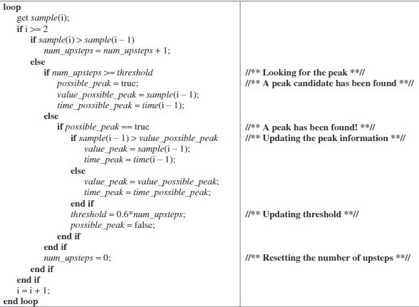
该算法主要是应用于低振幅的PPG信号。在动脉脉搏跳动时,局部血容量急剧增加。这在 PPG 信号上显示为收缩峰之前的rising edge。考虑到systolic rising edge 的陡度,可以合理地假设只有当血容量达到最大值时(即收缩峰出现时),该段的斜率才会从正变为负。基于该假设,组成 systolic rising edge 的每个点 f 都满足 ![]() ,并且提供了
,并且提供了
算法伪代码:

只要PPG波的斜率是正的,变量num_steps的值就会增加,如果斜率从正变为负,num_steps将重置为零。变量possible_peak是一个标志,通过它可以忽略波纹甚至舒张期峰值,可能会被错误地标记为收缩期峰值。阈值根据经验初始化为 0.6,并随着每次心跳更新其值
代码
def upslopes(x):

    # Peak detection
    th = 6
    pks = np.empty(0)
    pos_pk = np.empty(0)
    pos_pk_b = 0
    n_pos_pk = 0
    n_up = 0

    for i in range(1, len(x)):
        if x[i] > x[i - 1]:
            n_up = n_up + 1
        else:
            if n_up > th:
                pos_pk = np.append(pos_pk, i)
                pos_pk_b = 1
                n_pos_pk = n_pos_pk + 1
                n_up_pre = n_up
            else:
                pos_pk = pos_pk.astype(int)
                #print('Possible peaks: ' + str(pos_pk) + ', number of peaks: ' + str(n_pos_pk))
                if pos_pk_b == 1:
                    if x[i - 1] > x[pos_pk[n_pos_pk - 1]]:
                        pos_pk[n_pos_pk - 1] = i - 1
                    else:
                        pks = np.append(pks, pos_pk[n_pos_pk - 1])
                    th = 0.6*n_up_pre
                    pos_pk_b = 0
            n_up = 0
    ibis = pks.astype(int)

    return ibis
Modified-Scholkmann algorithm
这个算法基于Scholkmann 算法,首先计算长度为 N 的线性去趋势信号X上的局部最大值尺度图 (LMS local maxima scalogram ),其中X={ xt | 1≤t≤N }。 LMS 是Smax = [N/2]−1 缩放N列的矩阵。如果时间值 t∈{1…N} 和缩放s∈{1…Smax}是局部最大矩阵包含 0,否则包含 r+α(其中 r 是均匀分布的随机变量,α 是常量)
LMS可以被视为SxN矩阵的每个scale等级的最大值,在scale为1 时,如果信号值 xt 大于相邻位置的信号值即 xt >xt-1 和 xt >xt+1,矩阵会在时间t编码局部最大值。scale 2就是xt >xt-2 和 xt >xt+2。
LMS计算从第一个scale(通常是1)到[N/2]−1,但是只裁剪1到包含最多最大值的scale。最后就是跨尺度计算列标准差column-wise standard deviation,标准偏差为零的时间点标识最大值(峰)的位置。
Multi-scale Peak and Trough Detection Optimised for Periodic and Quasi-PeriodicNeuroscience Data这篇文章针对颅内压(ICP)波形数据,测试出最大scale是等效的信号波长的四分之一左右。
后文附带了matlab代码
% ----------
% Physiology Feature Extraction Toolkit% Dr Steven Bishop, 2015-16% Division of Anaesthesia, University of Cambridge, UK% Email: sbishop {AT} doctors.org.uk
% ----------
% PEAK_TROUGH_FINDER%% Based upon the algorithm by (with updates and optimisations):
% Scholkmann F, Boss J, Wolk M. An Efficient Algorithm for Automatic Peak% Detection in Noisy Periodic and Quasi-Periodic Signals. Algorithms 2012% (5), p588-603; doi:10.3390/a5040588
% ----------
% [peaks,troughs,maximagram,minimagram] = PEAK_TROUGH_FINDER(data, {max-interval})% data: input data as vector% sampling_frequency (optional): sampling frequency of input% Returns: vectors [peaks, troughs, maximagram, minimagram] containing
%  indices of the peaks and troughs and the maxima/minima scalograms
function [peaks,troughs,maximagram,minimagram] = new_peak_trough(data, varargin)
	N = length(data);
	if nargin == 2
		L = ceil(varargin{1}/2) -1;
	else
		L = ceil(N/2) -1;
	end
	%Detrend the data
	meanval = nanmean(data);
	data(isnan(data)) = meanval;
	data = detrend(data, 'linear');
	Mx = zeros(N, L);
	Mn = zeros(N, L);
	%Produce the local maxima scalogram
	for j=1:L
		k = j;
		for i=k+2:N-k+1
			if data(i-1) > data(i-k-1) && data(i-1) > data(i+k-1)
				Mx(i-1,j) = true;
				end
				if data(i-1) < data(i-k-1) &&data(i-1) < data(i+k-1)
				Mn(i-1,j) = true;
			end
		end
	end
	maximagram = Mx;
	minimagram = Mn;
	%Form Y the column-wise count of where Mx is 0, a scale-dependent distribution of
	%local maxima. Find d, the scale with the most maxima (== most number
	%of zeros in row). Redimension Mx to contain only the first d scales
	Y = sum(Mx==true, 1);
	[~, d] = max(Y);
	Mx = Mx(:,1:d);
	%Form Zx and Zn the row-rise counts of Mx and Mn's non-zero elements.
	%Any row with a zero count contains entirley zeros, thus indicating
	%the presence of a peak or trough
	Zx = sum(Mx==false, 2);
	Zn = sum(Mn==false, 2);
	%Find all the zeros in Zx and Zn. The indices of the zero counts
	%correspond to the position of peaks and troughs respectively
	peaks = find(~Zx);
	troughs = find(~Zn);
end
用python改写:
def MScholkmann(x):

    # Setup
    signal = x
    N = len(signal)
    L = int(np.ceil(N / 2) - 1)

    # Step 1: calculate local maxima and local minima scalograms

    # - detrend: this removes the best-fit straight line
    x = sp.detrend(signal, type="linear")

    # - initialise LMS matrices
    m_max = np.full((L, N), False)
    # m_min = np.full((L, N), False)

    # - populate LMS matrices
    for k in range(1, L):  # scalogram scales
        for i in range(k + 2, N - k + 1):
            if x[i - 1] > x[i - k - 1] and x[i - 1] > x[i + k - 1]:
                m_max[k - 1, i - 1] = True
    #       if x[i - 1] < x[i - k - 1] and x[i - 1] < x[i + k - 1]:
    #           m_min[k - 1, i - 1] = True

    # Step 2: find the scale with the most local maxima (or local minima)
    # - row-wise summation (i.e. sum each row)
    gamma_max = np.sum(m_max, axis=1)
    # the "axis=1" option makes it row-wise
    #gamma_min = np.sum(m_min, axis=1)
    # - find scale with the most local maxima (or local minima)
    lambda_max = np.argmax(gamma_max)
    #lambda_min = np.argmax(gamma_min)

    # Step 3: Use lambda to remove all elements of m for which k>lambda
    m_max = m_max[: (lambda_max + 1), :]
    #m_min = m_min[: (lambda_min + 1), :]

    # Step 4: Find peaks (and onsets)
    # - column-wise summation
    m_max_sum = np.sum(m_max == False, axis=0)
    #m_min_sum = np.sum(m_min == False, axis=0)
    peaks = np.asarray(np.where(m_max_sum == 0)).astype(int)
    #onsets = np.asarray(np.where(m_min_sum == 0)).astype(int)

    return peaks
其他
自动描绘器(论文是应用于ABP)
On an automatic delineator for arterial blood pressure waveforms
动脉血压 (ABP) 波形实际上由两个不同的分量调制,即心脏压力信号 cardiac pressure signaling 和迭代脉搏波反射 iterative pulse wave reflection

还有什么就再补充吧


