华为路由器MPLS VPN综合实验
目录
【实验题目】
【实验思路】
【实验记录】
一、公网部分
二、客户A的MPLS VPN
三、客户B的MPLS VPN
四、配置R7缺省指向公网
【实验题目】

【实验思路】
由题目可知,实验目的是要将客户A的站点1和站点2通过MPLS VPN连成一个私网,将客户B的站点1和站点2通过MPLS VPN连成另一个私网,MPLS VPN骨干网络和R4与R7之间的一条网线(这里假设是R4-GE4/0/0与R7-GE0/0/1这根网线)构成公网部分。
那么,首先要将公网做通和配置MPLS和配置BGP,即配置IP地址 ——> 配置OSPF路由 ——> 配置BGP(建立R2/R4对等体关系)——> 配置MPLS ,然后在R2、R4上配置VRF,为VRF接口配置IP地址,再分别为客户A和客户B的私网部分配置IP地址、使用静态或动态方式传递路由,最后在R2、R4上的各自VRF空间中通过双向重发布或BGP路由发布(BGP需配置为MP-BGP)。
至于R7访问R2/R3/R4的环回,在R7写缺省路由即可。
【实验记录】
一、公网部分
1. 配置IP地址
[r2]interface g0/0/2
[r2-GigabitEthernet0/0/2]ip address 23.0.0.1 24
[r2]interface LoopBack 0
[r2-LoopBack0]ip address 2.2.2.2 24
[r3]interface g0/0/0
[r3-GigabitEthernet0/0/0]ip address 23.0.0.2 24
[r3]interface g0/0/1
[r3-GigabitEthernet0/0/1]ip address 34.0.0.1 24
[r3]interface LoopBack 0
[r3-LoopBack0]ip address 3.3.3.3 24[r4]int g0/0/0
[r4-GigabitEthernet0/0/0]ip address 34.0.0.2 24
[r4]int g4/0/0
[r4-GigabitEthernet4/0/0]ip address 47.0.0.1 24
[r4]interface LoopBack 0
[r4-LoopBack0]ip address 4.4.4.4 24[r7]int g0/0/1
[r7-GigabitEthernet0/0/1]ip address 47.0.0.2 242. 配置OSPF
[r2]ospf 1 router-id 2.2.2.2
[r2-ospf-1]a 0
[r2-ospf-1-area-0.0.0.0]network 23.0.0.0 0.0.0.255
[r2-ospf-1-area-0.0.0.0]network 2.2.2.2 0.0.0.0
[r3]ospf 1 router-id 3.3.3.3
[r3-ospf-1]a 0
[r3-ospf-1-area-0.0.0.0]network 23.0.0.0 0.0.0.255
[r3-ospf-1-area-0.0.0.0]network 34.0.0.0 0.0.0.255
[r3-ospf-1-area-0.0.0.0]network 3.3.3.3 0.0.0.0[r4]ospf 1 router-id 4.4.4.4
[r4-ospf-1]a 0
[r4-ospf-1-area-0.0.0.0]network 34.0.0.0 0.0.0.255
[r4-ospf-1-area-0.0.0.0]network 47.0.0.0 0.0.0.255
[r4-ospf-1-area-0.0.0.0]network 4.4.4.4 0.0.0.03. 配置BGP
[r2]bgp 1
[r2-bgp]router-id 2.2.2.2
[r2-bgp]peer 4.4.4.4 as 1
[r2-bgp]peer 4.4.4.4 connect-interface LoopBack 0
[r4]bgp 1
[r4-bgp]router-id 4.4.4.4
[r4-bgp]peer 2.2.2.2 as 1
[r4-bgp]peer 2.2.2.2 connect-interface LoopBack 04. 配置MPLS
[r2]mpls lsr-id 2.2.2.2
[r2]mpls
Info: Mpls starting, please wait... OK!
[r2-mpls]mpls ldp
[r2-mpls-ldp]q
[r2]int g0/0/0
[r2-GigabitEthernet0/0/0]mpls
[r2-GigabitEthernet0/0/0]mpls ldp
[r3]mpls lsr-id 3.3.3.3
[r3]mpls
Info: Mpls starting, please wait... OK!
[r3-mpls]mpls ldp
[r3-mpls-ldp]q
[r3]interface g0/0/0
[r3-GigabitEthernet0/0/0]mpls
[r3-GigabitEthernet0/0/0]mpls ldp
[r3-GigabitEthernet0/0/0]int g0/0/1
[r3-GigabitEthernet0/0/1]mpls
[r3-GigabitEthernet0/0/1]mpls ldp[r4]mpls lsr-id 4.4.4.4
[r4]mpls
Info: Mpls starting, please wait... OK!
[r4-mpls]mpls ldp
[r4-mpls-ldp]q
[r4]int g0/0/0
[r4-GigabitEthernet0/0/0]mpls
[r4-GigabitEthernet0/0/0]mpls ldp
公网部分完成
二、客户A的MPLS VPN
1. 创建VRF空间
[r2]ip -instance a1
[r2--instance-a1]route-distinguisher 100:1
[r2--instance-a1-af-ipv4]-target 100:1 both
 IVT Assignment result:
Info: VPN-Target assignment is successful.
 EVT Assignment result:
Info: VPN-Target assignment is successful.
[r4]ip -instance a2
[r4--instance-a2]route-distinguisher 100:1
[r4--instance-a2-af-ipv4]-target 100:1 both
IVT Assignment result:
Info: VPN-Target assignment is successful.
EVT Assignment result:
Info: VPN-Target assignment is successful.2. 划分接口到VRF并配置IP地址
[r2]interface g0/0/0
[r2-GigabitEthernet0/0/0]ip binding -instance a1
Info: All IPv4 related configurations on this interface are removed!
Info: All IPv6 related configurations on this interface are removed!
[r2-GigabitEthernet0/0/0]ip address 192.168.2.2 24
[r4]interface g0/0/1
[r4-GigabitEthernet0/0/1]ip binding -instance a2
Info: All IPv4 related configurations on this interface are removed!
Info: All IPv6 related configurations on this interface are removed!
[r4-GigabitEthernet0/0/1]ip address 192.168.3.1 24
3. 客户A私网配置IP地址并使用静态方式传递路由
[r1]int g0/0/0
[r1-GigabitEthernet0/0/0]ip address 192.168.2.1 24
[r1]int LoopBack 0
[r1-LoopBack0]ip address 192.168.1.1 24
[r1]ip route-static 192.168.3.0 24 192.168.2.2
[r1]ip route-static 192.168.4.0 24 192.168.2.2
[r2]ip route-static -instance a1 192.168.1.0 24 192.168.2.1[r5]int g0/0/0
[r5-GigabitEthernet0/0/0]ip address 192.168.3.2 24
[r5]interface LoopBack 0
[r5-LoopBack0]ip address 192.168.4.1 24
[r5]ip route-static 192.168.1.0 24 192.168.3.1
[r5]ip route-static 192.168.2.0 24 192.168.3.1[r4]ip route-static -instance a2 192.168.4.0 24 192.168.3.24. 配置MP-BGP并发布路由
[r2]bgp 1
[r2-bgp]ipv4-family v4
[r2-bgp-af-v4]peer 4.4.4.4 enable
[r2-bgp-af-v4]q
[r2-bgp]ipv4-family -instance a1
[r2-bgp-a1]network 192.168.1.0 24
[r2-bgp-a1]network 192.168.2.0 24
[r4]bgp 1
[r4-bgp]ipv4-family v4
[r4-bgp-af-v4]peer 2.2.2.2 enable
[r4-bgp-af-v4]q
[r4-bgp]ipv4-family -instance a2
[r4-bgp-a2]network 192.168.3.0 24
[r4-bgp-a2]network 192.168.4.0 24


客户A的MPLS VPN私网完成
三、客户B的MPLS VPN
1. 创建VRF空间
[r2]ip -instance b1
[r2--instance-b1]route-distinguisher 200:1
[r2--instance-b1-af-ipv4]-target 200:1 b
 IVT Assignment result:
Info: VPN-Target assignment is successful.
 EVT Assignment result:
Info: VPN-Target assignment is successful.
[r4]ip -instance b2
[r4--instance-b2]route-distinguisher 200:1
[r4--instance-b2-af-ipv4]-target 200:1 b
[r4--instance-b2-af-ipv4]-target 200:1 both
IVT Assignment result:
Info: VPN-Target assignment is successful.
EVT Assignment result:
Info: VPN-Target assignment is successful.2. 划分接口到VRF并配置IP地址
[r2]interface g0/0/1
[r2-GigabitEthernet0/0/1]ip binding -instance b1
Info: All IPv4 related configurations on this interface are removed!
Info: All IPv6 related configurations on this interface are removed!
[r2-GigabitEthernet0/0/1]ip address 172.10.2.2 24
[r4]interface g0/0/2
[r4-GigabitEthernet0/0/2]ip binding -instance b2
Info: All IPv4 related configurations on this interface are removed!
Info: All IPv6 related configurations on this interface are removed!
[r4-GigabitEthernet0/0/2]ip address 172.10.3.1 243. 客户B私网配置IP地址并使用动态方式传递路由
[r6]int g0/0/0
[r6-GigabitEthernet0/0/0]ip address 172.10.2.1 24
[r6]int LoopBack 0
[r6-LoopBack0]ip address 172.10.1.1 24
[r6]rip 1
[r6-rip-1]v 2
[r6-rip-1]network 172.10.0.0
[r2]rip 1 -instance b1
[r2-rip-1]v 2
[r2-rip-1]network 172.10.0.0[r7]interface g0/0/0
[r7-GigabitEthernet0/0/0]ip address 172.10.3.2 24
[r7]int LoopBack 0
[r7-LoopBack0]ip address 172.10.4.1 24
[r7]ospf 2 router-id 7.7.7.7
[r7-ospf-2]a 0
[r7-ospf-2-area-0.0.0.0]network 172.10.3.0 0.0.0.255
[r7-ospf-2-area-0.0.0.0]network 172.10.4.1 0.0.0.0[r4]ospf 2 -instance b2 router-id 4.4.4.4
[r4-ospf-2]a 0
[r4-ospf-2-area-0.0.0.0]network 172.10.3.0 0.0.0.2554. 配置MP-BGP并双向重发布路由
[r2]bgp 1
[r2-bgp]ipv4-family -instance b1
[r2-bgp-b1]import-route rip 1

[r2]rip 1
[r2-rip-1]import-route bgp
[r4]bgp 1
[r4-bgp]ipv4-family -instance b2
[r4-bgp-b2]import-route ospf 2
[r4]ospf 2 -instance b2
[r4-ospf-2]import-route bgp
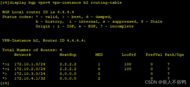

客户B的MPLS VPN私网完成
四、配置R7缺省指向公网
[r7]ip route-static 0.0.0.0 0 47.0.0.1
至此,实验全部完成!