【台大郭彦甫】Matlab入门教程超详细学习笔记六:高阶绘图(附PPT链接)
高阶绘图
- 前言
- 一、进阶二维绘图
-
- 1. 对数图
- 2.一图双y轴
- 3. 直方图
- 4. 条形图
- 5. 饼状图
- 6. 极坐标图
- 7. 阶梯图与取样图
- 8. 箱线图以及误差线图
- 9. 填充图
- 二、配色
-
- 1.RGB
- 2.数据可视化为图像
- 三、三维绘图
-
- 1. 2D VS 3D
- 2. 3D 点或线图
- 3. 曲面图
- 4. 矩阵等值线图
- 5. 网格曲面图下及曲面图下的等高线图
- 6. 视点控制以及打光设置
- 7. 绘制多边形
- 总结
前言
【台大郭彦甫】PPT链接:https://pan.baidu.com/s/1VXdy3HCBPexMK0csyehiZA 提取码:2io1
matlab官方帮助文档:https://ww2.mathworks.cn/help/
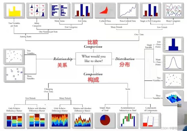
根据自己所需要的选择各类型的图。
一、进阶二维绘图
1. 对数图
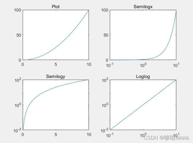
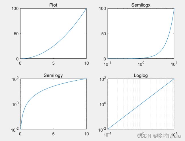
logspace(-1,1,100):x取 1 0 − 1 10^{-1} 10−1~ 1 0 1 10^{1} 101之间的100个变量semilogx(x,y): x坐标轴是对数坐标系,即使用 x 轴以 10 为基数的对数刻度和 y 轴的线性刻度创建一个绘图。semilogy(x,y):y坐标轴是对数坐标系,即使用 y 轴以 10 为基数的对数刻度和 x 轴的线性刻度创建一个绘图。loglog(x, y):x、y坐标都是对数坐标系
eg.
x = logspace(-1,1,100);
y = x.^2;
subplot(2,2,1);
plot(x,y);
title('Plot');
subplot(2,2,2);
semilogx(x,y);
title('Semilogx');
subplot(2,2,3);
semilogy(x,y);
title('Semilogy');
subplot(2,2,4);
loglog(x, y);
title('Loglog');
set(gca,'XGrid','on');
2.一图双y轴
-
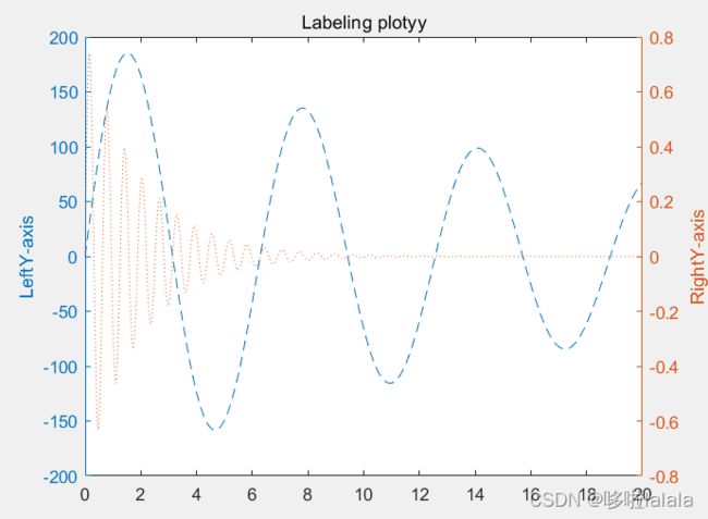
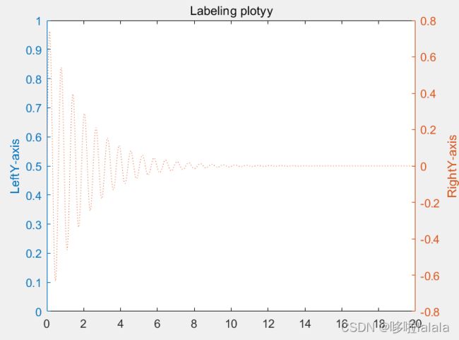
plotyy()以左、右不同纵轴绘制两条曲线。
y = a e − b x s i n ( c x ) y=ae^{-bx}sin(cx) y=ae−bxsin(cx)

-
[AX,H1,H2] = plotyy( ):返回给AX两个坐标区(Axes)的句柄(handle),AX(1)表示左边的坐标区的handle,AX(2)表示右边的坐标区的handle。返回给H1和H2每个绘图中Line对象的handle.
eg.
x = 0:0.01:20;
y1 = 200*exp(-0.05*x).*sin(x);
y2 = 0.8*exp(-0.5*x).*sin(10*x);
[AX,H1,H2] = plotyy(x,y1,x,y2);
set(get(AX(1),'Ylabel'),'String','LeftY-axis')
set(get(AX(2),'Ylabel'),'String','RightY-axis')
title('Labeling plotyy');
set(H1,'LineStyle','--');
set(H2,'LineStyle',':');
- 使用
yyaxis()分别激活左右两个坐标轴,分别设置。
x = 0:0.01:20;
y1 = 200*exp(-0.05*x).*sin(x);
y2 = 0.8*exp(-0.5*x).*sin(10*x);

yyaxis left;
p1 = plot(x,y1);
ylabel('LeftY-axis')
title('Labeling plotyy');
p1.LineStyle = '--';

yyaxis right;
p2 = plot(x,y2);
ylabel('RightY-axis')
p2.LineStyle = ':';
- 清除左侧曲线命令:
yyaxis left;
cla;
3. 直方图
- 直方图看整体情况
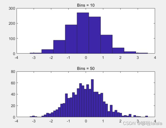
hist(y)默认十个等间隔区间,并返回每个范围内的Y的元素个数作为一行向量。hist(y,x)划分x个等间隔区间。
eg.
y = randn(1,1000);
subplot(2,1,1);
hist(y,10);
title('Bins = 10');
subplot(2,1,2);
hist(y,50);
title('Bins = 50');
4. 条形图
- 条形图看个别情况
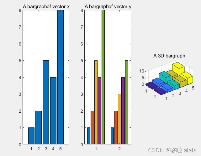
bar()创建一个条形图。
如果y是向量,y中每个向量对应一个条形,如图1;
如果y是矩阵,则根据y中的行进行分组,如图2;bar3()画3D图
eg.
x = [1 2 5 4 8];
y = [x;1:5];
subplot(1,3,1);
bar(x);
title('A bargraphof vector x');
subplot(1,3,2);
bar(y);
title('A bargraphof vector y');
subplot(1,3,3);
bar3(y);
title('A 3D bargraph');
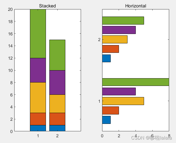
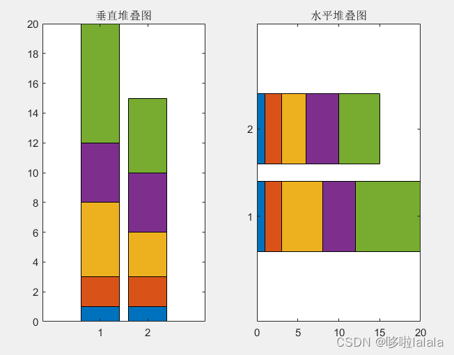
bar(y,'stacked')为堆叠条形图,为了可以展示总和为多少。barh(y)为水平条形图。
eg.
x = [1 2 5 4 8];
y = [x;1:5];
subplot(1,2,1);
bar(y,'stacked');
title('Stacked');
subplot(1,2,2);
barh(y);
title('Horizontal');
Exercise:stack the horizontal bar chart
x = [1 2 5 4 8];
y = [x;1:5];
subplot(1,2,1);
bar(y,'stacked');
title('垂直堆叠图');

subplot(1,2,2);
barh(y,'stacked');
title('水平堆叠图');
5. 饼状图
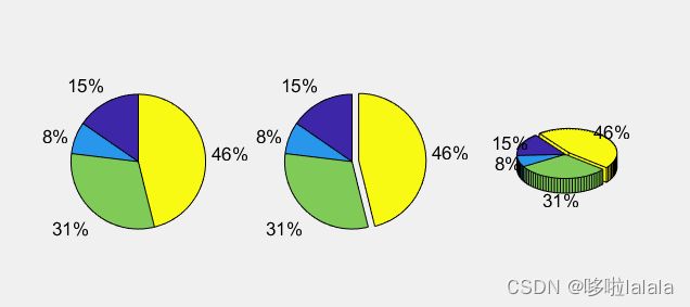
pie(a)使用a中的数据绘制饼状图,sum(a)≥0,则按比例绘制;sum(a)<1,则仅按比例绘制部分饼图。pie(a,explode)将对应explode元素设置为1,使该部分偏移出去,例图2。pie3()绘制3D饼图,例图3。pie(x,{'Taxes','Expenses','Profit'})使用{}设置标签。
eg.
a = [10 5 20 30];
subplot(1,3,1);
pie(a);
subplot(1,3,2);
pie(a, [0,0,0,1]);
subplot(1,3,3);
pie3(a, [0,0,0,1]);
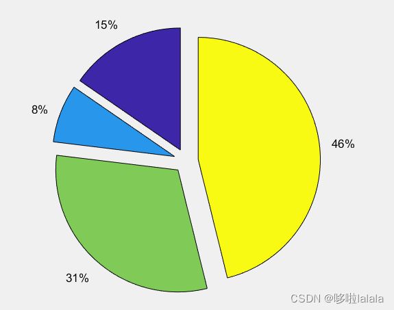
Exercise: separate all the pieces in the pie chart
a = [10 5 20 30];
pie(a, [1,1,1,1]);
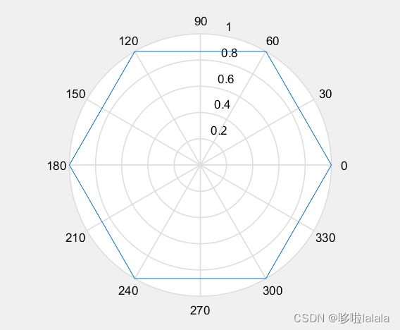
6. 极坐标图
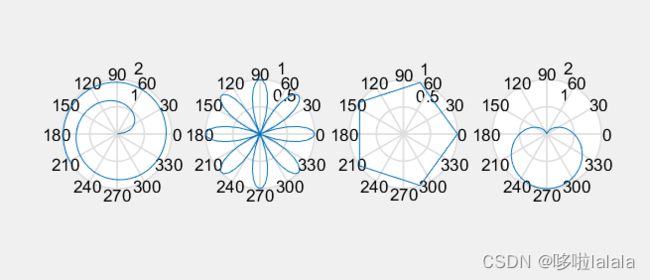
polar(theta,r)其中theta表示极角,r表示半径linspace用于产生生成线性间距向量:
linspace(x1,x2)返回包含 x1 和 x2 之间的 100 个等间距点的行向量。
linspace(x1,x2,n)生成 n 个点。这些点的间距为 (x2-x1)/(n-1)。- ones()创建全部为 1 的数组
- 在最新版本中推荐使用:polarplot()
eg.
x = 1:100;theta = x/10;
r = log10(x);
subplot(1,4,1);
polar(theta,r);
theta = linspace(0, 2*pi);
r = cos(4*theta);
subplot(1,4,2);
polar(theta, r);
theta = linspace(0, 2*pi, 6);
r = ones(1,length(theta));
subplot(1,4,3);
polar(theta,r);
theta = linspace(0, 2*pi);
r = 1-sin(theta);
subplot(1,4,4);
polar(theta , r);
Exercise: plot a hexagon on a polar chart
theta = linspace(0, 2*pi,7);
r = ones(1,length(theta));
polar(theta,r);
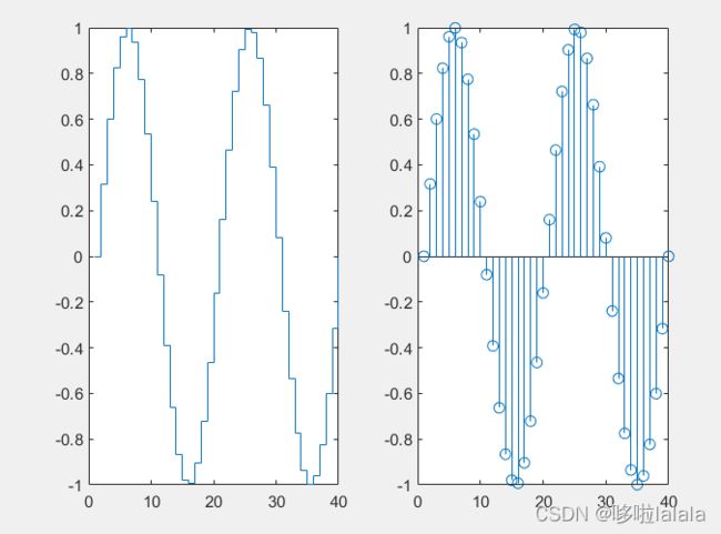
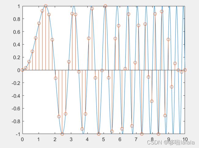
7. 阶梯图与取样图
stairs()阶梯图:使用平行与x、y轴的线段连接各点
stem()离散序列图:将各点与x轴垂直相连
eg.
x = linspace(0, 4*pi, 40);
y = sin(x);
subplot(1,2,1);
stairs(y);
subplot(1,2,2);
stem(y);
t = linspace(0,10,1000);
f = sin(pi*(t.^2/4));
plot(t,f);
hold on;
x = linspace(0,10,50);
y = sin(pi*(x.^2/4));
stem(x,y);
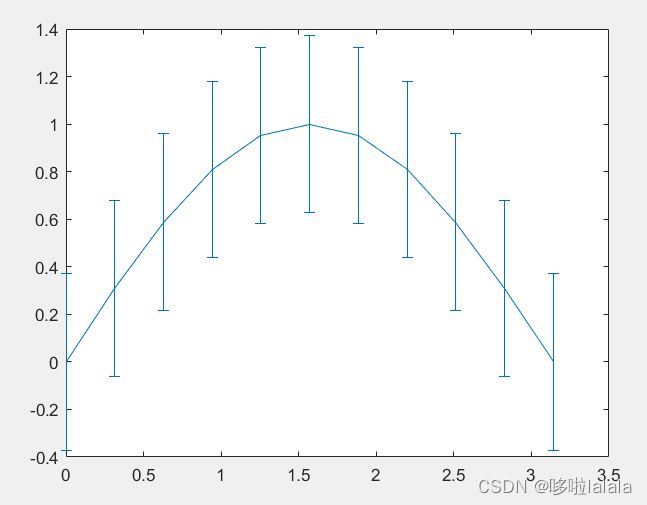
8. 箱线图以及误差线图
boxplot():用箱线图可视化汇总统计量errorbar()误差线
eg.
load carsmall
boxplot(MPG, Origin);
x=0:pi/10:pi; y=sin(x);
e=std(y)*ones(size(x));
errorbar(x,y,e)
9. 填充图
- 使用
plot()是画线,而使用fill()是画线且涂色 fill(x,y,ColorSpec)填充 x 和 y 指定的二维多边形(颜色由 ColorSpec 指定)
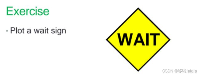
如下图fill(x,y,'r')画出多边形,并以红色填充。axis square off是axis square(使当前区域为正方形)和axis off(使数轴不可见)两个命令的组合命令。- text()添加文本信息
eg.
t =(1:2:15)'*pi/8;
x = sin(t);
y = cos(t);
fill(x,y,'r');
axis square off;
text(0,0,'STOP','Color', 'w','FontSize', 80, ...
    'FontWeight','bold','HorizontalAlignment','center');
t =(0:4)*pi/2;
x = sin(t);
y = cos(t);
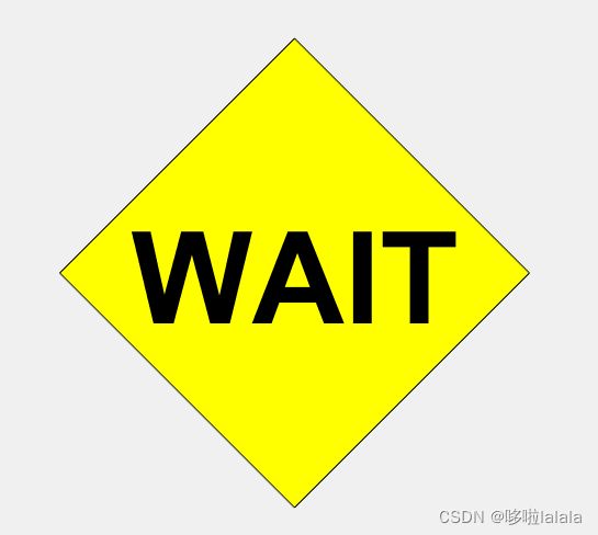
fill(x,y,'y');
axis square off;
text(0,0,'WAIT','Color', 'k','FontSize', 70, ...
    'FontWeight','bold','HorizontalAlignment','center');
- 要想设置填充多边形的边框,需要获取其
handle,进而下一步设置参数
t =(0:4)*pi/2;
x = sin(t);
y = cos(t);
h = fill(x,y,'y');
h.LineWidth = 5;
axis square off;
text(0,0,'WAIT','Color', 'k','FontSize', 70, ...
    'FontWeight','bold','HorizontalAlignment','center');
二、配色
1.RGB
-
[R G B]:一种颜色标准,通过对红、绿、蓝三个颜色相互之间的叠加来得到各式各样的颜色。通常使用0~255(十进制)之间的数来表示各成分占比。
-
比如白色 [255 255 255] 十六进制为 [FF FF FF],记作 #FFFFFF
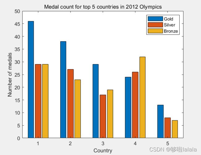
- G、S、B三个向量需要先转置再串联起来,因为bar()是将矩阵的每一行分为一组,分别画出条形;
eg.
G = [46 38 29 24 13];
S = [29 27 17 26 8];
B = [29 23 19 32 7];
h = bar(1:5, [G' S' B']);
title('Medal count for top 5 countries in 2012 Olympics');
ylabel('Number of medals');
xlabel('Country');
legend('Gold', 'Silver', 'Bronze')
改变颜色
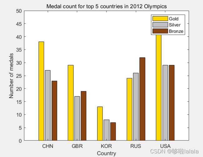
- 在进行颜色设置时,matlab似乎不支持使用0~255的数组来表示[R G B],将0~255的数组每一项均除以255, 转换为0~1来表示即可。
G = [46 38 29 24 13];
S = [29 27 17 26 8];
B = [29 23 19 32 7];
% 指定字符串标记x轴
str=categorical({'USA','CHN','GBR','RUS','KOR'});
% 画图的同时将各条形的handle赋给h,并将FaceColor属性设置为flat
h = bar(str, [G' S' B'],'FaceColor','flat');

for i=1:size(G',1)      % 将每组第一个条形设置为金色
    h(1).CData(i,:)=[1,0.843,0];
end
for i=1:size(G',1)      % 将每组第二个条形设置为银色
    h(2).CData(i,:)=[0.753 0.753 0.753];
end
for i=1:size(G',1)      % 将每组第三个条形设置为铜色
    h(3).CData(i,:)=[.545,.27,.0745];
end
title('Medal count for top 5 countries in 2012 Olympics');
ylabel('Number of medals'); xlabel('Country');
legend('Gold', 'Silver', 'Bronze')  % 加上图例
2.数据可视化为图像
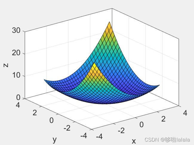
meshgrid函数用来生成网格矩阵- surf():画曲面图
box on显示坐标轴轮廓
[x, y] = meshgrid(-3:.2:3,-3:.2:3);
z = x.^2 + x.*y + y.^2;
surf( x, y, z);
box on;
set(gca,'FontSize', 16);
zlabel('z');
xlim([-4 4]);
xlabel('x');
ylim([-4 4]);
ylabel('y');
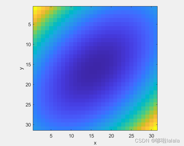
imagesc(z)将矩阵z中的元素数值按大小转化为不同颜色,并在坐标轴对应位置处以这种颜色染色
imagesc(z);
axis square;
xlabel('x');
ylabel('y');
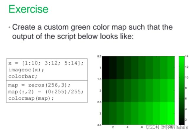
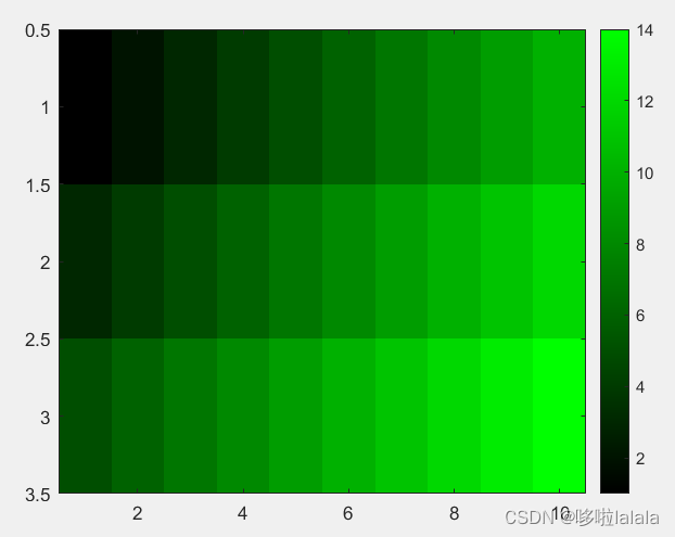
x = [1:10; 3:12; 5:14];
imagesc(x);
colorbar;
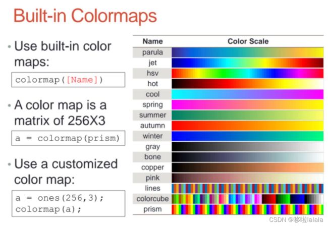
map = zeros(256,3);
map(:,2) = (0:255)/255;
colormap(map);
三、三维绘图
1. 2D VS 3D
x=0:0.1:2*pi;
plot(x,sin(x));
2. 3D 点或线图
-
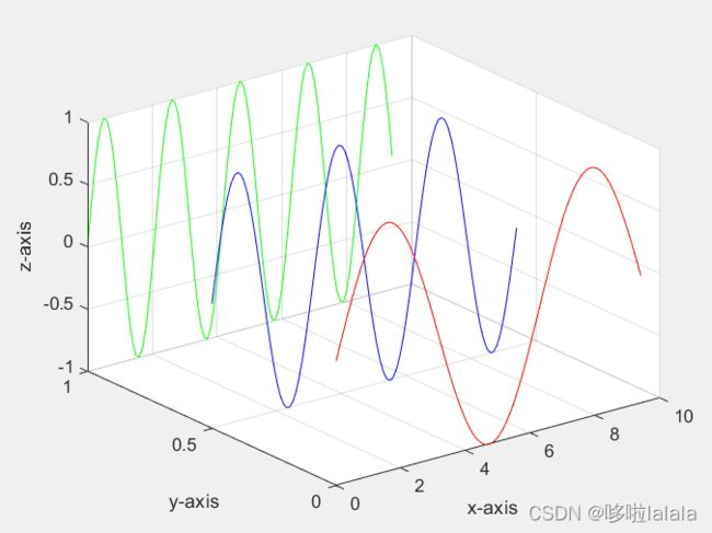
plot3(X,Y,Z)在 3-D 空间中绘制坐标。 -
要绘制一组由线段连接的坐标,请指定XYZ为相同长度的向量。
要在同一组轴上绘制多组坐标,请至少将 XYZ,其中至少一个指定为矩阵,并将其他坐标指定为向量。
x=0:0.1:3*pi;
z1=sin(x);
z2=sin(2.*x);
z3=sin(3.*x);
y1=zeros(size(x));
y3=ones(size(x));
y2=y3./2;
plot3(x,y1,z1,'r',x,y2,z2,'b',x,y3,z3,'g');
grid on;
xlabel('x-axis');
ylabel('y-axis');
zlabel('z-axis');
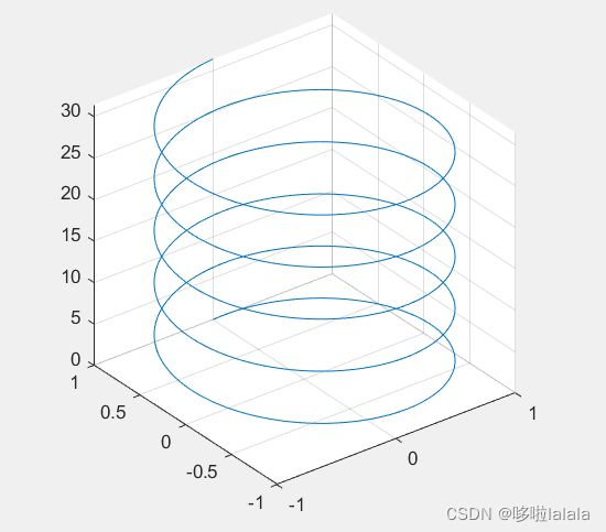
t = 0:pi/50:10*pi;
plot3(sin(t),cos(t),t)
grid on;
axis square;
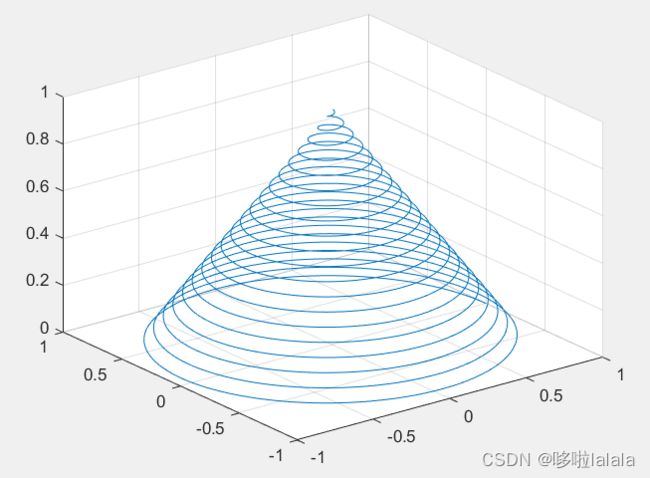
turns = 40*pi;
t = linspace(0,turns,4000);
x = cos(t).*(turns-t)./turns;
y = sin(t).*(turns-t)./turns;
z = t./turns;
plot3(x,y,z);
grid on;
3. 曲面图
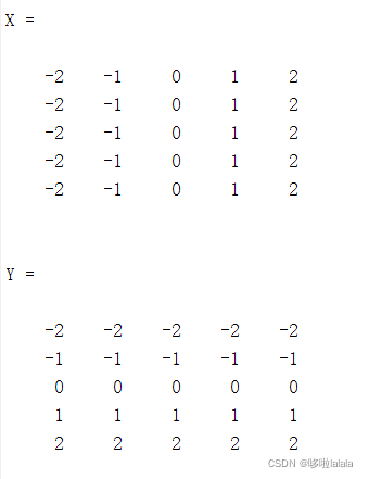
[X,Y]=meshgrid(x,y):基于向量 x 和 y 中包含的坐标返回二维网格坐标。也就是说前面给出的x、y只是一个向量,而画网图需要x、y两个范围围出来的面上的所有点,meshgrid(x,y)则给出这个面上所有的点。
x = -2:1:2;
y = -2:1:2;
[X,Y] = meshgrid(x,y)
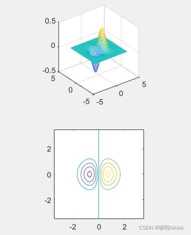
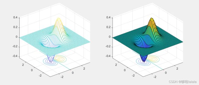
surf(X,Y,Z)创建三维曲面图,该图面是具有纯边色和实心脸色的三维曲面。该函数将矩阵中的值绘制为由 和 定义的 x-y 平面中网格上方的高度。表面的颜色根据 指定的高度而变化。(绘制网格并填充颜色)mesh和surf的区别:surf会把颜色贴在上面;
x = -3.5:0.2:3.5;
y = -3.5:0.2:3.5;
[X,Y] = meshgrid(x,y);
Z = X.*exp(-X.^2-Y.^2);
subplot(1,2,1);
mesh(X,Y,Z);
subplot(1,2,2);
surf(X,Y,Z);
- 现在新版Matlab通常直接使用
surf(x,y,x.*exp(-x.^2-(y').^2))也能得到以上效果。如下
x = -3.5:0.2:3.5;
y = -3.5:0.2:3.5;
subplot(1,2,1);
mesh(x,y,x.*exp(-x.^2-(y').^2));
subplot(1,2,2);
surf(x,y,x.*exp(-x.^2-(y').^2));
4. 矩阵等值线图
- contour:等高线/轮廓
x = -3.5:0.2:3.5;
y = -3.5:0.2:3.5;
[X,Y] = meshgrid(x,y);
Z = X.*exp(-X.^2-Y.^2);
subplot(2,1,1);
mesh(X,Y,Z);
axis square;
subplot(2,1,2);
contour(X,Y,Z);
axis square;
-
在contour后面加数值可以让contour画线更加紧密;例如
contour(Z,[-.45:.05:.45]); -
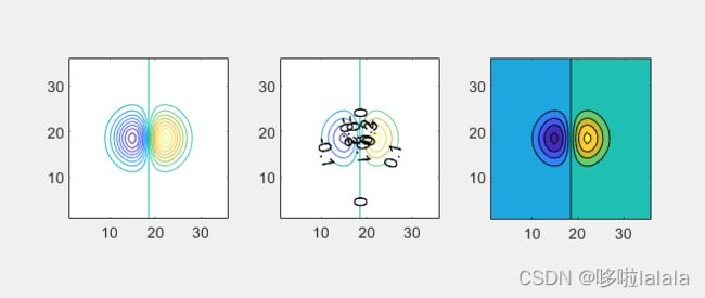
我们还可以在图上把数值标上去,用clabel指令:
clabel(C,h); -
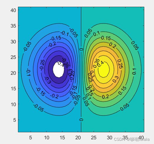
也可以给contour涂颜色,
contourf(),f是fill的意思;
x = -3.5:0.2:3.5;
y = -3.5:0.2:3.5;
[X,Y] = meshgrid(x,y);
Z = X.*exp(-X.^2-Y.^2);
subplot(1,3,1);
contour(Z,[-.45:.05:.45]);
axis square;
subplot(1,3,2);
[C,h] = contour(Z);
clabel(C,h);
axis square;
subplot(1,3,3);
contourf(Z);
axis square;
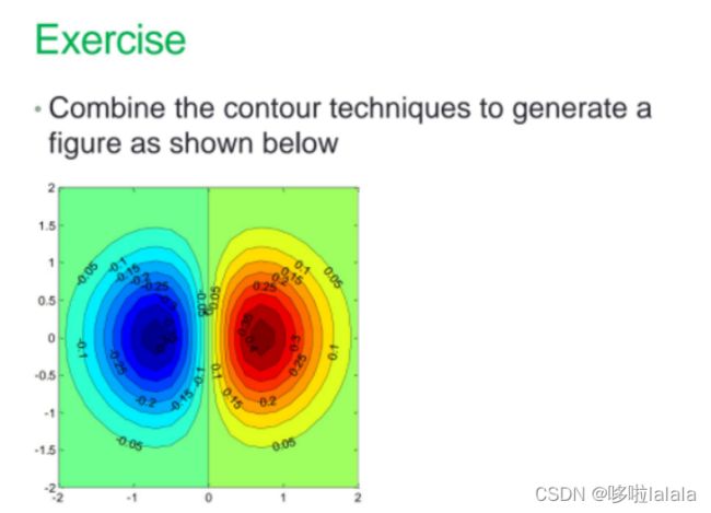
x=-2:0.1:2;
y=-2:0.1:2;
[X,Y]=meshgrid(x,y);%绘制网格
Z=X.*exp(-X.^2-Y.^2);
[C,h]=contourf(Z,[-0.4:0.05:0.4]);%填充、改变线松紧、准备添加数字表示
axis square;%显示坐标轴
clabel(C,h);%添加数字表示
5. 网格曲面图下及曲面图下的等高线图
- meshc() and surfc()
x = -3.5:0.2:3.5;
y = -3.5:0.2:3.5;
[X,Y] = meshgrid(x,y);
Z = X.*exp(-X.^2-Y.^2);
subplot(1,2,1);
meshc(X,Y,Z);
subplot(1,2,2);
surfc(X,Y,Z);
6. 视点控制以及打光设置
view(Az,El)其中Az为方位角,El为高度角;也可以输入三个参数,view(x,y,z),其中(x,y,z)是直角坐标系中一个矢量。
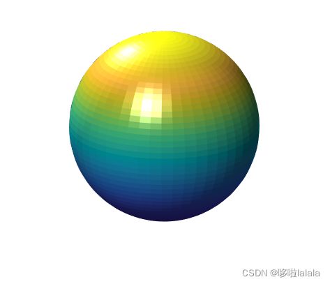
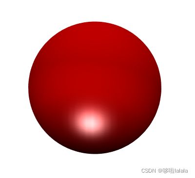
sphere(50);
shading flat;
light('Position',[1 3 2]);%添加灯光,让球更立体
light('Position',[-3 -1 3]);
material shiny;
axis vis3d off;%不显示三维坐标系
set(gcf,'Color',[1 1 1]);
view(-45,20);%这个可以决定角度
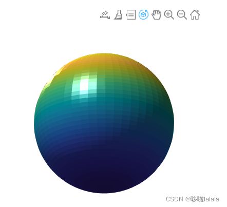
- 可以旋转查看球体:使用图形界面的三维旋转选项,这时左下角会出现观察的球坐标角度表示
- 定义
light的打光位置和颜色:
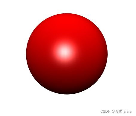
[X, Y, Z] = sphere(64);
h = surf(X, Y, Z);
axis square vis3d off;
reds = zeros(256, 3);
reds(:, 1) = (0:256.-1)/255;
colormap(reds);
shading interp;
lighting phong;
set(h, 'AmbientStrength', 0.75, 'DiffuseStrength', 0.5);
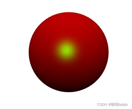
L1 = light('Position', [-1, -1, -1]);
set(L1, 'Position', [-1, -1, 1]);
set(L1, 'Color', 'g');
7. 绘制多边形
- patch()绘制一个或多个填充多边形区域
v = [0 0 0; 1 0 0 ; 1 1 0; 0 1 0; 0.25 0.25 1; 0.75 0.25 1; 0.75 0.75 1; 0.25 0.75 1];
f = [1 2 3 4; 5 6 7 8; 1 2 6 5; 2 3 7 6; 3 4 8 7; 4 1 5 8];
subplot(1,2,1);
patch('Vertices', v, 'Faces', f, 'FaceVertexCData',hsv(6),'FaceColor','flat');
view(3);
axis square tight;
grid on;
subplot(1,2,2);
patch('Vertices', v, 'Faces', f, 'FaceVertexCData',hsv(8),'FaceColor','interp');
view(3);
axis square tight;
grid on;
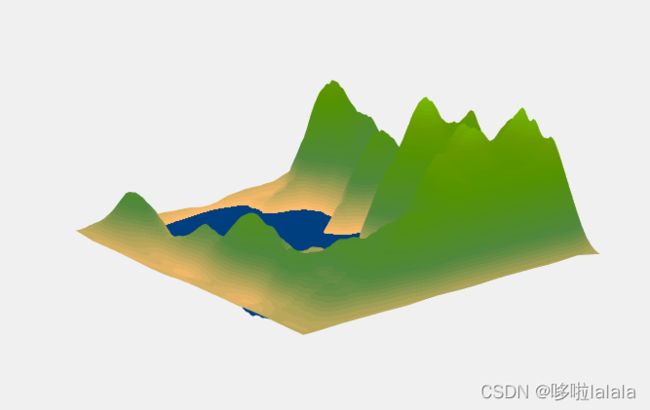
load cape
X=conv2(ones(9,9)/81,cumsum(cumsum(randn(100,100)),2));
surf(X,'EdgeColor','none','EdgeLighting','Phong','FaceColor','interp');
colormap(map);
caxis([-10,300]);
grid off; axis off;
总结
以上就是第六节的内容,本部分介绍了matlab的高阶绘图部分。
