5轨迹生成
文章目录
- Introduction
-
- 全局与局部方法
-
- 全局与局部对比
- 轨迹生成
-
- T(what)
- 为什么需要平滑轨迹呢
- Y(why)
- W(how)
- 微分平坦(Differential Flatness)
-
- T
-
- Quadrotor dynamics
- quadrotor states
- Orientation
- Angular velocity
- Summary
- Close the planning-control loop
- polynomial Trajectories
- Minimum-snap
-
- Smooth 1D Trajectory
- Optimization-based Trajectory Generation
- Multi-segment minimum-snap trajectory
- constraints
- Objective function
- Convex Optimization
-
- Convex function and convex set
- MiniMum-snap求闭式解
-
- Decision variable mapping
- fixed(constrained) and free variable separation
- Hierachical approach(用于无人机)
- trajectory optimazition considering obstacle
-
- better solutions
- Implementation Details
-
- convex solvers
- Numerical Stability
-
- Normalization
-
- Other engineering stuff
- Time Allocation
-
- Problem Definition
- Naive solution
- Iterative numerical solution
- Homework
-
- 题目
- 结果
Introduction
全局与局部方法
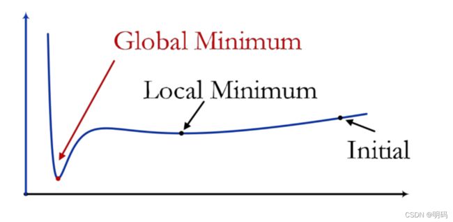
global Methods: Exploration and Exploitation
Local Methods: Deterministic Optimization(取决于问题的初值,和迭代步数)

图搜索分辨率最优
PRM*/RRT*: https://ompl.kavrakilab.org/
A*: https://github.com/qiao/PathFinding.js/
JPS: https://github.com/KumarRobotics/jps3d

CHOMP: https://github.com/ros-planning/moveit
DDP/iLQR: https://github.com/anassinator/ilqr
MPC/NMPC: https://www.embotech.com/products/forcespro/overview/
Flatness: https://github.com/ZJU-FAST-Lab/GCOPTER
全局与局部对比
| Global Methods | Local Methods | |
|---|---|---|
| pros | • Global optimality | |
| • Handling environmental complexity | ||
| • Portable | ||
| • Zero-order Information | • Local optimality | |
| • Handling dynamics complexity | ||
| • Fast in high-dimensional space | ||
| • Promising convergence rate | ||
| cons | • Slow in high-dimensional space• Inconvenient to incorporate dynamics• Poor convergence rate | • More involved• High-order information• Shallow local minima |
| 全局最优,便捷(0阶信息),处理环境复杂度,在高维空间缓慢,难以引入动力学约束,特别是在高维流形,收敛慢 |
能够处理复杂动力学约束,快速处理高阶问题,但需要建模,参数辨识,需要高阶信息,容易陷入局部最优。
Some works try to combine both, but still inherit most disadvantages.
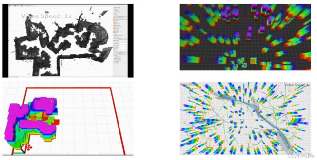
全局和本地方法通常以解耦方式(前端 + 后端)部署在实际应用中。
Bry et al., Aggressive flight of fixed-wing and quadrotor aircraft in dense indoor environments, IJRR 2015.
Gao et al., Gradient-based online safe trajectory generation for quadrotor flight in complex environments, IROS 2017.
Zhou et al., Ego-planner: An esdf-free gradient-based local planner for quadrotors. RAL 2020.
Wang et al., Generating Large-Scale Trajectories Efficiently using Double Descriptions of Polynomials, ICRA 2021.
轨迹生成
T(what)

Briefly: Trajectories are time-parameterized paths.
Trajectories consist of spatial and temporal profiles.
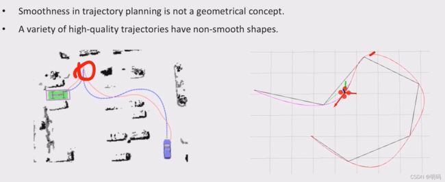
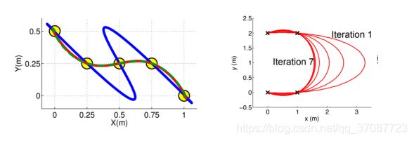
注意轨迹并不一定是光滑的
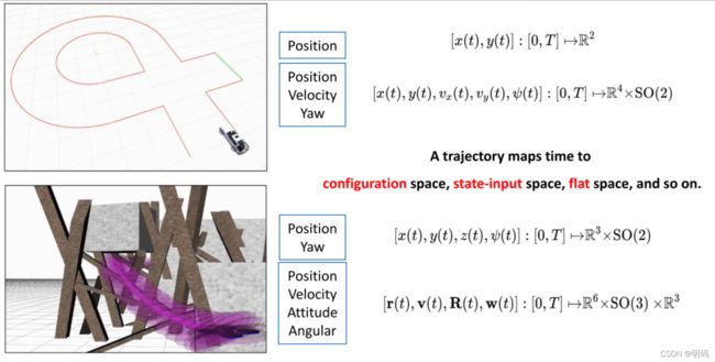
A trajectory maps time to configuration space, state-input space, flat space, and so on.
轨迹可以参数
为什么需要平滑轨迹呢
•适合自主移动。
•速度/高阶动力学状态不能突变。满足微分约束
•机器人不能在转弯时停下来。
•节约能源。轨迹生成的目标函数可以是最小关于状态和输入的能量泛函
Y(why)
问:我们有前端(寻径),为什么必须有后端(轨迹生成)?
见上
问:前端是动态可行的,为什么后端必须要存在,因为需要考虑到机器人的运动学约束,另外需要包含时间信息,便于避开动态障碍物
如蓝色为优化的轨迹,更适合汽车的运动

W(how)
- 边界条件:起点、目标位置(方向)
- 中间条件:中继节点waypoint,位置(方向)
- 通过路径规划(A*, RRT*等)可以找到路标点(中继节点)
- 平滑度评价函数
- 通常转化为**“输入”变化率的最小化**问题
微分平坦(Differential Flatness)
T
常微分方程描述系统的一种特性,给定一个动态系统满足

如果存在一个由状态x和输入的?决定z,那么称这个系统是微分平坦的。
z就是平坦输出,能够唯一决定系统的所有状态和输入。将用z表达的状态和输入带入微分方程,是一个恒等式。
把曲面拉成平面,也就是平坦
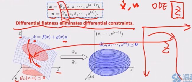
Mellinger et al., Minimum Snap Trajectory Generation and Control for Quadrotors, ICRA 2011.
Faessler et al., Differential Flatness of Quadrotor Dynamics Subject to Rotor Drag for Accurate Tracking of High-Speed Trajectories, RAL 2017.
Ferrin et al., Differential Flatness Based Control of a Rotorcraft For Aggressive Maneuvers. IROS 2011.
Mu et al., Trajectory Generation for Underactuated Multirotor Vehicles with Tilted Propellers via a Flatness-based Method, AIM 2019.
Watterson et al., Control of Quadrotors Using the Hopf Fibration on SO(3), ISRR 2017.
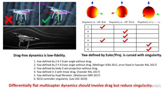
把位姿SE(3)拉直到平面,会引入奇异点,使用hopf fibration,这里没有引入风阻,只有一个奇异点
四旋翼飞行器的状态和输入可以写成代数函数组合,也就是四种仔细选择的平面输出及其导数
-
能够自动生成轨迹
-
平坦输出空间中的任何光滑轨迹(具有合理有界导数(不会快速发散))都可以被欠驱动的四轴飞行器跟随。
-
a possible choice

Ψ \varPsi Ψ偏航角
θ \theta θ 俯仰角
ϕ \phi ϕ 横滚角 -
平坦输出空间的轨迹

T 0 , T M T_0,T_M T0,TM 时间段,定义在 R × S O ( 2 ) R \times SO(2) R×SO(2)
Quadrotor dynamics
- Nonlinear dynamics

- 转动方程 Euler Equation
- where R 旋转矩阵,w世界坐标系 B 物体坐标系 l力臂长度
note : 无人机产生的推力方向只能够垂直于桨叶平面
quadrotor states
- 位置,方向,线速度,角速度(在物体坐标系下)

需要高维空间的变量整理成低维空间的变量,主要的思路是通过,位置和一个偏航角去表示这12个状态

- 运动方程:等价于上面两个方程 Newton &Euler Equation


note:位置、速度和加速度只是平面输出的导数,一般选择加速度做优化,机器人的姿态没有优化
[参考论文](Minimum Snap Trajectory Generation and Control for Quadrotors , Daniel Mellinger and Vijay Kumar)
Orientation

where z B z_B zB为合加速度的单位向量,t使用 x , y , z x,y,z x,y,z的二阶导和重力加速度表示
Angular velocity
Summary
-
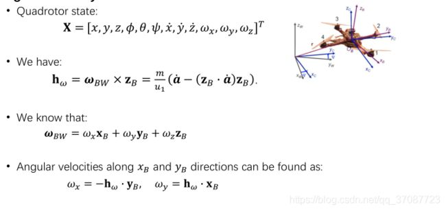
Quadrotor state
X = [ x , y , z , ϕ , θ , ψ , x ˙ , y ˙ , z ˙ , w x , w y , w z ] T X=\left[ x,y,z,\phi ,\theta ,\psi ,\dot{x},\dot{y},\dot{z},w_x,w_y,w_z \right] ^T X=[x,y,z,ϕ,θ,ψ,x˙,y˙,z˙,wx,wy,wz]T -
Flat outputs
σ = [ x , y , z , ψ ] T \sigma =\left[ x,y,z,\psi \right] ^T σ=[x,y,z,ψ]T -
Position, velocity, acceleration
Derivatives of flat outputs -
Orientation
x c = [ cos σ 4 , sin σ 4 , 0 ] T → R B = [ x B , y B , z B ] \mathrm{x}_{\mathrm{c}}=\left[ \cos \sigma _4,\sin \sigma _4,0 \right] ^T\rightarrow \boldsymbol{R}_{\boldsymbol{B}}=\left[ \mathbf{x}_{\mathbf{B}},\mathbf{y}_{\mathbf{B}},\mathbf{z}_{\mathbf{B}} \right] xc=[cosσ4,sinσ4,0]T→RB=[xB,yB,zB] -
Angular velocity
w x = − h w ⋅ y B , w y = h w ⋅ x B , w z = ψ ˙ z w ⋅ z B w_x=-h_w\cdot y_B,w_y=h_w\cdot \mathrm{x}_{\mathrm{B}},w_z=\dot{\psi}\mathrm{z}_{\mathrm{w}}\cdot \mathrm{z}_{\mathrm{B}} wx=−hw⋅yB,wy=hw⋅xB,wz=ψ˙zw⋅zB
z_B?
Close the planning-control loop

通过轨迹规划得到的位置信息 p d e s p_des pdes速度信息(位置信息的导数),加速度信息(位置信息的二阶导)和偏航角输入位置控制器,计算出推力 u 1 u_1 u1和姿态信息,将姿态信息输入姿态控制器解算出三个方向的力矩 u 2 , u 3 , u 4 u _2 , u _3 , u_4 u2,u3,u4, 4 u 2 , u 3 , u 4 4 u_2,u_3,u_4 4u2,u3,u4共同完成对无人机的控制。
polynomial Trajectories
- Flat outputs: σ = [ x , y , z , ψ ] T \sigma =\left[ x,y,z,\psi \right] ^T σ=[x,y,z,ψ]T
- Trajectory in the space of flat outputs:
- σ ( t ) = [ T 0 , T M ] → R 3 × S O ( 2 ) \mathrm{\sigma}\left( \mathrm{t} \right) =\left[ \mathrm{T}_0,\mathrm{T}_{\mathrm{M}} \right] \rightarrow \mathbb{R}^3\times SO\left( 2 \right) σ(t)=[T0,TM]→R3×SO(2)
- 多项式函数可以用来指定平面输出空间中的轨迹
•多项式阶平滑判据的简单确定
•简单的封闭形式的导数计算
•在三维中解耦轨迹生成
Minimum-snap
Smooth 1D Trajectory

note:对于一段轨迹中的一个参数,需要有t=0,t=T分别表示,解释为何要乘以2 了

- 平滑直线段的角。
•首选恒速运动。
•首选零加速度。 - 需要特殊处理短段。
Optimization-based Trajectory Generation
minimum snap trajectory 可以理解为最小化加加加速度轨道
关于牛顿第二定律深度理解:
Jerk: 所受力的变化率。(如每秒增加一牛顿)
snap: 所受力的变化率的变化。(如前一秒增加一牛顿,接下来一秒增加两牛顿,第二秒受力与最初相比增加了三牛顿)
最小snap,就让jerk变化比较小。如果snap为0,就代表每秒加速度稳定增加(受力稳定增加)
在平面输出空间中显式地最小化某些导数
•最小冲击:最小角速度,良好的视觉跟踪
•最小弹跳:最大差动推力,节省能源
NOTE:如果是针对minimum jerk,则需要提供位置,速度,角速度3个状态量。如果只考虑起点和终点,则有 2 ∗ 3 = 6 2*3=6 2∗3=6个状态。同时考虑多项式形式包含有 x 0 x_{0} x0(也就是常数项),所以最终的N=5
同样的道理,如果minimum snap,则需要提供位置,速度,加速度,以及角速度,4个状态量。所以N = 2 ∗ 4 − 1 = 7 2*4-1 = 7 2∗4−1=7
Note2: 如果考虑多段的情况,例如K段,则minimum jerk ,需要 (k-1) +3 +3= k+5 , 这里只要求能够连续的到达中间点,至于以怎样的速度,怎样的加速度到达这个点,是优化出来的,不属于约束 。
假设每一段的阶数为N ,则每一段轨迹所能提供的自由度为为N+1。N阶多项式可以提供N次导数,加上原多项式,即为N+1。 所以,总计 (N+1)*k.
(N+1)*k>= k+5. 则 N_{min} = 5/k. 表明段数越多,则提供的阶次越低。
每一个分段都是多项式;每个分段的多项式都是相同的阶次,这样对于问题的求解比较简单;每一段的时间间隔都是已知的(也可以不已知,但那就是优化时间间隔的问题了)
Multi-segment minimum-snap trajectory

一个多项式曲线过于简单,一段复杂的轨迹很难用一个多项式表示,所以将轨迹按时间分成多段,每段各用一条多项式曲线表示,形如:


M为轨迹的段数,i指一段的第几项(0,N)
Minimum Snap的最小化目标函数为snap(jerk的导数,jerk为加速度的导数),对于一段轨迹,最小化jerk选择的阶数为5(2x3-1,3个未知量分别为位置、速度、加速度),最小化snap选择的阶数为7(2x4-1,4个未知量分别为位置、速度、加速度、jerk)。实际过程中,考虑最坏情况,k段距离阶数的选择与1段轨迹相同。
- 每一段都是一个多项式。
•不需要确定阶次,但保持相同的阶次可以使问题更简单。
•必须知道每个段的时间长度!
constraints
- different timeline
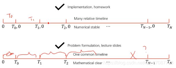
时间分配的方法:匀速分配或梯形分配,假设每段polynomial内速度满足匀速或梯形速度变化,根据每段的距离将总时间T分配到每段。
这里的轨迹分段和时间分配都是初始分配,在迭代算法中,如果corridor check和feasibility check不满足条件,会插点或增大某一段的时间
用的是后一种
Objective function
m i n i m u m s n a p : min f ( p ) = min ( p ( 4 ) ( t ) ) 2 m i n i m u m j e r k : min f ( p ) = min ( p ( 3 ) ( t ) ) 2 m i n i m u m a c c e : min f ( p ) = min ( p ( 2 ) ( t ) ) 2 minimum~snap:~\min f(p)=\min (p^{(4)}(t))^2 \\ minimum~jerk:~\min f(p)=\min (p^{(3)}(t))^2 \\ minimum~acce:~\min f(p)=\min (p^{(2)}(t))^2 \\ minimum snap: minf(p)=min(p(4)(t))2minimum jerk: minf(p)=min(p(3)(t))2minimum acce: minf(p)=min(p(2)(t))2

function Q = getQ(n_seg, n_order, ts)
    Q = [];
    for k = 1:n_seg
        Q_k = zeros(n_order + 1, n_order + 1);
        %#####################################################
        % STEP 1.1: 计算第k段的矩阵Q_k
        for i = 4:n_order
            for j = 4:n_order
                Q_k(i+1,j+1) = factorial(i)/factorial(i-4)*factorial(j)/factorial(j-4)/(i+j-n_order)*ts(k)^(i+j-n_order);
            end
        end
        Q = blkdiag(Q, Q_k);
    end
end
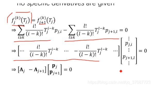
- 导数约束(A 的构建)
举例
function [Aeq beq]= getAbeq(n_seg, n_order, waypoints, ts, start_cond, end_cond)
    n_all_poly = n_seg*(n_order+1);
    %#####################################################
    % p,v,a,j 的起点约束,
    Aeq_start = zeros(4, n_all_poly);
    % STEP 2.1: write expression of Aeq_start and beq_start
    Aeq_start(1:4,1:8) = getCoeffCons(0);
    beq_start =  start_cond';

    %#####################################################
    % p,v,a,j 的终端约束
    Aeq_end = zeros(4, n_all_poly);
    t = ts(end);
    Aeq_end(1:4, end-7:end) = getCoeffCons(t);
    beq_end =  end_cond';

    %#####################################################
    % 中点的位置约束
    Aeq_wp = zeros(n_seg-1, n_all_poly);
    beq_wp = zeros(n_seg-1, 1);

    for k = 0:1:n_seg-2
        beq_wp(k+1, 1) = waypoints(k+2);
        coeff = getCoeffCons(ts(k+1));
        Aeq_wp(k+1, 1+k*8:8+k*8) = coeff(1, :);
    end

    %#####################################################
    % 连续性约束
    Aeq_con_p = zeros(n_seg-1, n_all_poly);
    beq_con_p = zeros(n_seg-1, 1);
    Aeq_con_v = zeros(n_seg-1, n_all_poly);
    beq_con_v = zeros(n_seg-1, 1);
    Aeq_con_a = zeros(n_seg-1, n_all_poly);
    beq_con_a = zeros(n_seg-1, 1);
    Aeq_con_j = zeros(n_seg-1, n_all_poly);
    beq_con_j = zeros(n_seg-1, 1);
    Aeq_con = [Aeq_con_p; Aeq_con_v; Aeq_con_a; Aeq_con_j];
    beq_con = [beq_con_p; beq_con_v; beq_con_a; beq_con_j];

    for k = 0:1:n_seg-2
        Aeq_con(1+4*k:4+4*k,1+8*k:8+8*k) = getCoeffCons(ts(k+1));
        Aeq_con(1+4*k:4+4*k,1+8*(k+1):8+8*(k+1)) = -getCoeffCons(0);
    end

    %#####################################################
    % 构造约束矩阵
    Aeq = [Aeq_start; Aeq_end; Aeq_wp; Aeq_con];
    beq = [beq_start; beq_end; beq_wp; beq_con];
end
function coeff = getCoeffCons(t)
    coeff = [1,  1*t,  1*t^2,  1*t^3,  1*t^4,  1*t^5,  1*t^6,  1*t^7;
             0,  1,    2*t,    3*t^2,  4*t^3,  5*t^4,  6*t^5,  7*t^6;
             0,  0,    2,      6*t,    12*t^2, 20*t^3, 30*t^4, 42*t^5;
             0,  0,    0,      6,      24*t,   60*t^2, 120*t^3,210*t^4];
end
%main
clc;clear;close all;
path = ginput() * 100.0;

n_order       = 7;% order of poly
n_seg         = size(path,1)-1;% segment number
n_poly_perseg = (n_order+1); % coef number of perseg

ts = zeros(n_seg, 1);
% calculate time distribution in proportion to distance between 2 points
% dist     = zeros(n_seg, 1);
% dist_sum = 0;
% T        = 25;
% t_sum    = 0;
%
% for i = 1:n_seg
%     dist(i) = sqrt((path(i+1, 1)-path(i, 1))^2 + (path(i+1, 2) - path(i, 2))^2);
%     dist_sum = dist_sum+dist(i);
% end
% for i = 1:n_seg-1
%     ts(i) = dist(i)/dist_sum*T;
%     t_sum = t_sum+ts(i);
% end
% ts(n_seg) = T - t_sum;

% or you can simply set all time distribution as 1
for i = 1:n_seg
    ts(i) = 1.0;
end

poly_coef_x = MinimumSnapQPSolver(path(:, 1), ts, n_seg, n_order);
poly_coef_y = MinimumSnapQPSolver(path(:, 2), ts, n_seg, n_order);


% display the trajectory
X_n = [];
Y_n = [];
k = 1;
tstep = 0.01;
for i=0:n_seg-1
    %#####################################################
    % STEP 3: get the coefficients of i-th segment of both x-axis
    % and y-axis
    for t = 0:tstep:ts(i+1)
        X_n(k)  = polyval(Pxi, t);
        Y_n(k)  = polyval(Pyi, t);
        k = k + 1;
    end
end

plot(X_n, Y_n , 'Color', [0 1.0 0], 'LineWidth', 2);
hold on
scatter(path(1:size(path, 1), 1), path(1:size(path, 1), 2));


function poly_coef = MinimumSnapQPSolver(waypoints, ts, n_seg, n_order)
    start_cond = [waypoints(1), 0, 0, 0];
    end_cond   = [waypoints(end), 0, 0, 0];
    %#####################################################
    % STEP 1: compute Q of p'Qp
    Q = getQ(n_seg, n_order, ts);
    %#####################################################
    % STEP 2: compute Aeq and beq
    [Aeq, beq] = getAbeq(n_seg, n_order, waypoints, ts, start_cond, end_cond);
    f = zeros(size(Q,1),1);
    poly_coef = quadprog(Q,f,[],[],Aeq, beq);
end
Convex Optimization
Convex function and convex set

一个函数是严格凸函数当且仅当条件二和 x = y x=y x=y时才取等号
参考自:Convex Optimization,Daniel Palomar,HKUST
如果在一个集合任意连接一条线,如果都在集合内,那便是凸集
师曰:将一个问题转化一个凸优化问题没有系统化方法
凸优化问题求解

范围:SOCP>QCQP>QP SOCP>LP
SDP可以覆盖前面所有问题,一般planning问题转化到
上面几个问题便可以求解了
MiniMum-snap求闭式解
Decision variable mapping
优化变量的映射
- 多项式轨迹的直接优化是数值不稳定的,对多项式系数p,可以针对多个点(有物理意义)
- 首选改变变量的映射,而不是优化线段端点导数
- 我们有 M j p j = d j M_jp_j=d_j Mjpj=dj, p j = M j − 1 d j p_j=M_j^{-1}d_j pj=Mj−1dj其中j是一个映射矩阵,它将多项式系数映射到导数,优化路标点的v,a

给出一个构建M矩阵的例子如下:P->M

可以看出M可以通过将某段轨迹初始时刻t=0(上三行)和末尾时刻t=T(下三行)代入上式得到。
只考虑p,v,a的话,M的表达式如下
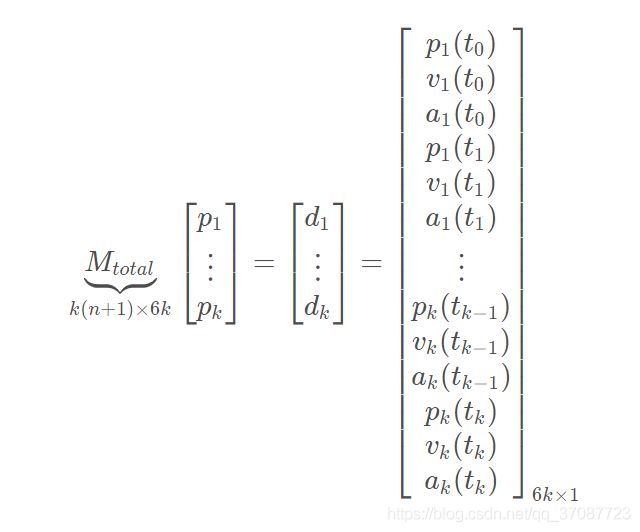
M t o t a l M_{total} Mtotal 是已知的(怎么构造可参见文章一种的等式约束构造方法),而 d 中只有少部分(起点、终点的pva等)是已知的,其他大部分是未知的。如果能够求出d ,那么轨迹参数可以通过 p= M − 1 d M^{-1}d M−1d很容易求得。
参考:Polynomial Trajectory Planning for Aggressive Quadrotor Flight in Dense Indoor Environments , Charles Richter, Adam Bry, and Nicholas Roy
fixed(constrained) and free variable separation
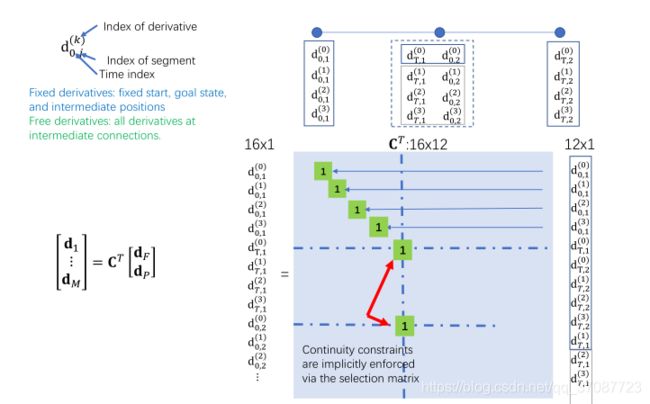
使用选择矩阵C来分离自由(dP)和受约束(dF)变量
自由变量:未指定的导数,仅由连续性约束强制执行,即


对R进行分块
转化成一个可以求解的无约束二次规划
封闭的形式:


对dp求偏导为0,求J的最优

对于两段轨迹,构造 C T C^T CT,如图所示,相应变量对应即可
映射矩阵C
参考
Hierachical approach(用于无人机)
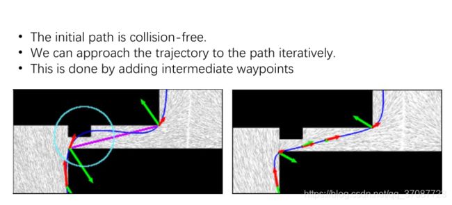
trajectory optimazition considering obstacle
发生碰撞就在中间加入路标点,不断加入直至没有碰到障碍物optimazition
better solutions
-
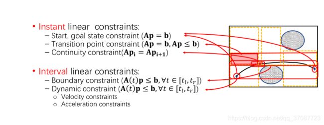
Smooth Trajectory Generation with Guaranteed Obstacle Avoidance

-
How to make constraints globally activated
迭代地检查极值并添加额外的约束。 -
迭代求解非常耗时。
-
总会产生过于保守的轨迹。
-
约束太多,计算量大。
论文
Online generation of collision-free trajectories for quadrotor flight in unknown cluttered environments , J. Chen, ICRA 2016
A hybrid method for online trajectory planning of mobile robots in cluttered environments , L Campos-Macías, RAL 2017
Implementation Details
convex solvers
- 我们的目标式制定一个轨迹生成问题转化为凸优化约束
- 许多现成的方法(off-the-shelf)能帮我们解决这个问题
- 根据需要选择一个求解器

CVX 数学公式直接表达
Mosek 功能全面
OOQP QP问题 代码开源
GLPK LP问题
Numerical Stability
Normalization
首先是时间的标准化
在很小间隔的时间段内不生成轨迹
将短期持续时间缩放到一个(1,0)区间里的数(归一化),或者将比例因子添加到曲线的所有部分
note: 使用相对坐标轴

然后是尺度(空间)的标准化
适应条件是处于大规模的场景,如waypoint x = 100.0 m x=100.0m x=100.0m情况,使得我们仅需要考虑一个小问题(沙盒),重新调整解决方案
这两种操作大大提高了实际计算的稳定性。
Other engineering stuff
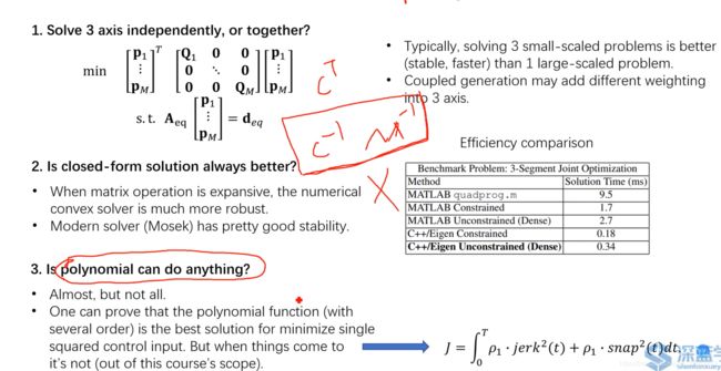
要不要3轴独立去解?通常求解要好一点
闭式解是不是更好?这个计算力较大,一般商用不会用,会用QP去求数值解
多项式是不是最优表达?如果仅是jerk 或者snap ,那么就是最优解
Time Allocation
Problem Definition
Naive solution
使用“梯形速度”时间剖面来获得每个片段的时间持续时间。
•假设在每一块上,加速到最大值,速度→减速为0。
•加速度+ 最大速度+ de-accelerate。
•使用预期的平均速度来获得每个部件的持续时间。

缺点
论文:Online generation of collision-free trajectories for quadrotor flight in unknown cluttered environments , J. Chen, ICRA 2016
Fast, dynamic trajectory planning for a dynamically stable mobile robot , M. Shomin, IROS 2014
Iterative numerical solution
不能优化到最优解,只能够求数值的导数,计算耗时间,不能解析式求导

Homework
题目
作业1.1:在matlab中,使用“quadprog”QP求解器,写下一个Minisnap轨迹生成器
作业1.2:在matlab中,根据闭合解生成Minisnap轨迹
作业2.1:在c++ /ROS中,使用OOQP求解器,写下一个最小snap轨迹生成器
作业2.2:在c++ /ROS中,利用Eigen,基于闭式求解解生成最小snap轨迹
