SystemVerilog之接口详解
1.入门实例
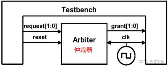
测试平台连接到 arbiter的例子:包括测试平台, arbiter仲裁器, 时钟发生器 和连接的信号。
Arbiter里面可以自定义发送的权重, 是轮询还是自定义
grant表示仲裁出来的是哪一个,也即只有0,1,因此图中grant的取值只有00 01 10 不可能出现11。
grant_valid表示grant是否有效。
-
使用端口
- 顶层连接
module top; logic[1:0] grant, request; logic grant_valid; bit clk,rst; always #5 clk=~clk; arb_port a1(grant, grant_valid, request, rst, clk); test t1(grant, grant_valid, request, rst, clk); endmodule- 仲裁器模型
module arb_port(output logic [1:0] grant, output logic grant_valid, input logic [1:0] request, input logic rst, input logic clk); … always@(posedge clk or posedge rst) begin if(rst) grant <=2'b00; else … end endmodule- 测试平台
module test(input logic [1:0] grant,
            input logic grant_valid,
            output logic [1:0] request,
            input logic rst,
            input logic clk);
    initial begin
        @(posedge clk) request <=2'b01;
        // 驱动了request01
        $display("@%05: Drove req=01",$time);
        repeat(2) @(posedge clk )
            if(grant_valid &&(grant!=2'b01))
                // 通常情况下 request是01,那么grant也是01
                $display("@%0t:a1:grant!=2’b01",$time);
        …
        $finish;
    end
endmodule
这种方法的缺点就是若DUT arb_port的端口需要改变,在test和top中的声明都要改变。
在真实的设计中, 往往含有数百个端口信号,因此,sv中推荐使用一种interface的结构。
2.接口定义
使用接口简化连接。
逻辑设计日益复杂,模块之间的通信必须分割成独立的实体。
SV使用接口来连接不同模块。接口可以看作一捆智能连线,它连接了DUT和验证平台, 它包括了连接,同步(clocking block)。
时钟可以是接口的一部分或者是一个独立的端口。
- 接口声明
interface arb_if(input bit clk);
    logic[1:0] grant,request;
    logic grant_valid;
    logic rst;
endinterface
- 采用接口的顶层模块
module top;
    bit clk;
    always #5 clk=~clk;
    arb_if arbif(clk);// 例化接口
    arb a1(arbif);    // 连接DUT
    test t1(arbif);   // 连接tb
endmodule:top
若仲裁器的端口无法修改为接口,则需要连接验证人员自己定义的接口到端口上:
module top;
    bit clk;
    always #5 clk=~clk;
    arb_if arbif(clk); 							//例化接口
    arb_port a1(.grant(arbif.grant), 			//连接DUT
                .grant_valid(arbif.grant_valid),
                .request(arbif.request),
                .rst (arbif.rst),
                .clk (arbif.clk));
    test t1(arbif); 							//连接tb
endmodule:top
- 使用接口的仲裁器,接口信号必须使用非阻塞赋值来驱动。
// arbif是例化名称
module arb(arb_if arbif);
    …
    always@(posedge arbif.clk or posedge arbif.rst);
    begin
        if(arbif.rst)
            arbif.grant <= 2'b00;
        else
            arbif.grant <= next_grant;
        …
    end
endmodule
- 使用接口的测试平台:
module test(arb_if arbif);
    …
    initial begin
        …
        @(posedge arbif.clk);
        arbif.request <= 2'b01;
        $display("@%0t: Drove req=01",$time);
        repeat(2) @(posedge arbif.clk);
        if(arbif.grant != 2'b01)
            $display("@%0t: a1:frant!=2'b01",$time);
        $finish;
    end
endmodule:test
问题:上述的接口定义中没有指明方向
interface arb_if( input bit clk);
    logic[1:0] grant,request;
    logic grant_valid;
    logic rst;
endinterface
没有指定方向,默认是inout,引入modport给信号分组,可以根据不同的module去定义不同的端口方向
一般情况下TB与DUT端口方向相反,除了clk与rst复位信号
例:使用modport结构将信号分组并指定方向
interface arb_if(input bit clk);
    logic[1:0] grant,request;
    logic rst;
    modport TEST(output request, rst,input grant, clk);
    modport DUT(input request, rst, clk,output grant);
    modport MONITOR(input request, grant, rst, clk);
endinterface
使用时钟同步块将request与grant优化后:
interface arb_if(input bit clk);
    logic [1:0] grant, request;
    logic rst;
    // 声明一个时钟模块cb
    clocking cb @(posedge clk);
        output request;
        input grant;
    endclocking
    // 调用cb
    modport TEST (clocking cb,output rst);
    modport DUT (input request, rst, output grant);
endinterface
则module定义的时候端口例化就变成:注意观察括号中的变化
module arb(arb_if.DUT arbif);
    …
endmodule
module test(arb_if.TEST arbif);
    …
endmodule
module monitor(arb_if.MONITOR arbif);
    …
endmodule
通常情况下,还可以去monitor监视上面各种信号的行为
module monitor(arb_if.MONITOR arbif);
    always@(posedge arbif.request[0]) begin
        $display("@%0t:request[0] asserted",$time);
        @(posedge arbif.grant[0])
        $display("@%0t:grant[0] asserted",$time);
    end
    always@(posedge arbif.request[1]) begin
        $display("@%0t:request[1] asserted",$time);
        @(posedge arbif.grant[1])
        $display("@%0t:grant[1] asserted",$time);
    end
endmodule
优缺点
- 优点:
- 便于设计重用;
- 可以替代原来需要在模块或者程序中重复声明并且位于代码内部的一系列信号,减少连接错误的可能性
- 要增加一个新信号时,,只需要在接口中声明一次,不需要在更高层的模块层声明, 进一步减少错误;
- modport允许一个模块将接口的一系列信号捆绑到一起,为信号指定方向;
- 缺点:
- 对于点对点的连接,使用modport跟使用信号列表的端口一样冗余(A与B之间如果就例化了一次,就会冗余);
- 必须同时使用信号名和接口名,会使模块变得更加冗长;
- 如果连接两个模块使用的是一个不会被重用的专用协议,使用接口需要做比端口连线更多的工作;
- 连接两个不同的接口很困难;一个新的接口可能包含了现有接口的所有信号并新增了信号,需要拆分独立的信号并正确的驱动;
总之:瑕不掩瑜,尽量使用interface,方便后续维护修改。
端口能做的,接口90%都能做,模块里面可以例化模块,模块可以例化接口,接口可以例化接口,但是接口不能例化模块
实例:根据design,设计出test bench,分别用端口连接、接口连接实现,并体会他们的异同
-
design
module arb_port(output logic [1:0] grant, output logic grant_valid, input logic [1:0] request, input logic rstn, input logic clk); logic pri; // 时序逻辑 always_ff @(posedge clk or negedge rstn) begin // 默认两个端口0,1,在rst复位之后,0端口的优先级高 if(!rstn) pri <=0; // 每来一个clock,pri就发生翻转 else pri<=~pri; end // 组合逻辑 always_comb begin // 按位或,只要request等于10 01 11,grand_valid都等于1,也即grand有效 grant_valid = |request; if(request== 2'b01 || request==2'b10) grant = request; // request同时为1,就会比较优先级 else if (request==2'b11) // 无优先级的case unique case(pri) // 比较优先级,优先级为0,就输出0口 1'b0: grant = 2'b01; 1'b1: grant = 2'b10; endcase else begin grant_valid = 0; grant =0; end end endmodule -
使用端口
module test(input logic [1:0] grant, input logic rant_valid, output logic [1:0] request, input logic rstn, input logic clk); initial begin @(posedge clk) request <=2’b01; $display("@%05: Drove req=01",$time); repeat(2) @(posedge clk ) ... end endmodule -
使用接口
module test(arb_if.TB arbif); initial begin arbif.rstn=1; repeat(2) @(posedge arbif.clk); arbif.rstn=0; // assert repeat(5) @(posedge arbif.clk); arbif.rstn=1; // release @(posedge arbif.clk) arbif.request <=2'b01; $display("@%05t: Drove req=01",$time); repeat(2) @(posedge arbif.clk); arbif.request <=2'b10; $display("@%05t: Drove req=10",$time); repeat(2) @(posedge arbif.clk); arbif.request <=2'b11; $display("@%05t: Drove req=11",$time); repeat(2) @(posedge arbif.clk); end endmodule -
定义接口
interface arb_if(input bit clk); logic [1:0] grant; logic [1:0] request; logic grant_valid; logic rstn; modport TB(input grant_valid,grant,clk,output request,rstn); modport DUT(input request,rstn,clk,output grant_valid,grant); endinterface -
顶层模块
module top;
    bit clk;
    always #5 clk = ~clk;
    arb_if arbif(clk);
    test u_test(arbif);
    // 由于端口无法修改为接口,因此手动连接定义的接口到端口上
    arb_port u_arb(
        .grand(arbif.grand),
        .grand_valid(arbif.grand_valid),
        .request(arbif.request),
        .rstn(arbif.rstn),
        .clk(clk)
    );
endmodule
在编译器中编译的顺序是有要求的,也即要先编译底层,最后再编译top顶层。同时,使用接口的时候需要确保在模块与程序块之外声明接口变量例如``include “arb_if.sv”`
3.接口同步
接口信号采样与驱动就使用到了接口同步
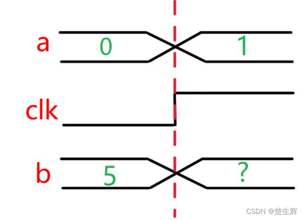
在RTL仿真时候会遇到信号竞争问题也即(Delta cycle仿真异常行为)。
例:b的值应该取clk上升沿之前的值0,但是却取了1
为了防止Deltal cycle的发生,因此我们采用clocking block(只能在testbench里面用)
在clocking block,所有信号的采样和驱动,都是跟时钟同步的(但要注意采样与驱动的不同)。
interface arb_if(input bit clk);
    logic [1:0] grant, request;
    logic reset;
    // 声明一个时钟模块cb
    clocking cb @(posedge clk);
        output request;
        input grant;
    endclocking
    // 调用cb
    modport TEST (clocking cb,output reset);
    modport DUT (input request, reset, output grant);
endinterface
通过clocking block完成同步,也即每一步操作都是跟clock对齐的,这样就完成request与grant的同步
program automatic test(bus_if.TB bus);
    initial begin
        @bus.cb; //在时钟块的有效时钟沿触发
        repeat(4) @bus.cb; //等待4个有效时钟沿
        @bus.cb.grant; //监测grant信号的变化(上升,下降)
        @(posedge bus.cb.grant); //监测grant信号的上升沿
        @(negedge bus.cb.grant); //监测grant信号的下降沿
        wait (bus.cb.grant==1); // 监测一个电平值, 若监测不到, 则一直等待
        @(posedge bus.cb.grant or negedge bus.reset); //监测grant上升沿,reset的下降沿
    end
endprogram
注意:在测试模块的时钟块中,使用modport的时候,任何同步接口信号都必须加上接口名(arbif)和时钟名称(cb),例如request信号,要写成arbif.cb.request。
4.接口采样与驱动
-
接口采样:当从时钟块中读取信号的时候,是在时钟沿之前得到的采样值
test程序块对clocking cb中的输入信号grant进行采样。 采样输出为arbif.cb.grant
// interface中定义的clocking block
interface arb_if(input bit clk);
    logic [1:0] grant, request;
    logic reset;
    // 声明一个时钟模块cb
    clocking cb @(posedge clk);
        output request;
        input grant;
    endclocking
    // 调用cb
    modport TEST (clocking cb,output reset);
    modport DUT (input request, reset, output grant);
endinterface

program test(arb_if.TEST arbif);
    initial begin
        $monitor("@%0d: grant=%h", $time, arbif.cb.grant);
        #50;
    end
endprogram

module arb(arb_if.DUT arbif);
    initial begin
        arbif.grant = 1; // @ 0ns
        #12 arbif.grant = 2; // @ 12ns
        #18 arbif.grant = 3; // @ 30ns
    end
endmodule
DUT的信号输出grant,clock block的cb.grant输出如波形所示。
在30ns处,DUT的grant的值在时钟沿跳变,同时TEST的cb.grant也在该时钟沿触发输出,但此时它采样的值还是该时刻之前的值2。
简而言之:采样拿旧值
-
接口驱动:在test中驱动同步信号arbif.cb.request ,在DUT中监测arbif.request的输出
program test(arb_if.TEST arbif);
    initial begin
        #7 arbif.cb.request <= 3;  // @ 7ns
        #10 arbif.cb.request <= 2; // @ 17ns
        #13 arbif.cb.request <= 1; // @ 30ns
        #15 $finish;
    end
endprogram

module arb(arb_if.DUT arbif);
    initial
        $monitor("@%0t: req=%h", $time, arbif.request);
endmodule
test中arb.cb.request,DUT中request的波形如图:
注意:30ns处arb.cb.request的变化立刻在上升沿被传送到arb.request上。因为在clocking block中输出信号的默认延迟为#0,软件在编译时, clocking block中 的输出信号要晚于被采样信号的变化,但在波形上观察不出来。
驱动也即就是test的输出,也即给DUT去使用的,由于需要立刻赋值给DUT,因而驱动是拿新值
简而言之:驱动拿新值
-
总结:在clocking block中,采样(input)和驱动(output)信号遵循如下原则:
同步后的采样信号,都是前一个状态的值。
同步后的驱动信号,都是当前状态的值。
到底是驱动还是采样,是由clock中的定义的信号方向决定的,而clocking block只能用于TB,因此:
在Test中,input就是对DUT的输出进行采样,output就是对DUT进行驱动,模拟了电路的一种属性
例如按下reset按钮,就必须立刻生效,如果要采样DUT的output的值的时候,就需要使用clocking block去采样。
5.接口中的双向信号
双向信号inout:inout必须定义为wire。
interface master_if(input bit clk);
    wire[7:0] data;

    clocking cb@(posedge clk);
        inout data;
    endclocking

    modport TEST(clocking cb);
endinterface
program test(master_if mif);
    initial begin
        mif.cb.data <='z; 	   //高阻态
        @mif.cb;
        $display(mif.cb.data); //从总线读取
        @mif.cb;
        mif.cb.data <=7'h5a;   //驱动总线
        @mif.cb;
        mif.cb.data <='z; 	   //释放总线
    end
endprogram
由于SV的用户参考手册中没有明确定义如何驱动接口中的异步双向信号, 故可用以下两种方法:
-
连续赋值语句
-
虚接口 virtual interface
6.为什么在程序块中不能使用always块
testbench中,程序的运行是有序性的:初始化,驱动激励信号,收取设计对激励的反馈,最后结束。当最后一个initial模块结束后,这个仿真也结束了,就像执行了$finish一样。而 always 语句是没有结束的,需要$exit来指定结束;
如果确实需要用一个always块, 可以使用**initial forever**来完成相同的事情; 所以initial forever在testbench中可以使用,功能类似于always。
program块中不支持always语句(编译会报错)
在program可以通过initial forever来代替,后续一般会使用initial forever去产生clock。
7.时钟发生器
program bad_generator (output bit clk, out_sig);
    bit clk=0, out_sig=0;
    initial
        forever #5 clk <= ~clk;
    initial
        // 这里输出了两个时钟,这个out_sig看起来是clk的二分频。
        forever @(posedge clk)
            out_sig <= ~out_sig;
endprogram
上例将时钟的产生定义到了program中,这样就会产生速度问题,时钟的翻转和信号变化同时的,应该判定谁的变化在前?
可能会引起竞争状态。 所以应该在module或者class中声明clk
module clock_generator (output bit clk);
    bit clk = 1;
    always #5 clk = ~clk; // Use blocking assignment
endmodule
8.虚接口
interface 封装了modue的端口(ports)、方向(modports)、同步关系 ( clocking block)interface 简化了模块之间的连接,但是无法很好地适用于基于OOP的测试平台,无法在program ,class中进行实例化。
为了解决这个问题, System Verilog引入了virtual interface的概念。 使用virtual interface是为了消除绝对路径,尽可能的减少验证代码的大面积修改。绝对路径:以前在TB里面引用都是接口.xxx等,使用虚接口之后,减少大面积的修改。
virtual interface的本质是指针,是指向interface的指针,即virtual interface是可以在class中实例化的数据类型,使用virtual interface可与被测设计(DUT)进行间接地通信,而无需使用层次结构引用。
如图所示:interface将测试平台与DUT分开。 virtual interface在TB的不同位置操纵一组虚拟信号,而不是直接操纵实际的信号。
在测试平台使用virtual interface时,需要满足以下3个要求:
-
实例化的接口必须正确连接到DUT。
// 创建一个interface简化与DUT的连接 interface counter_if (input logic clk); logic load_valid; logic [3:0]load_value; endinterface module tb_top; logic rstn,clk; logic [3:0]out; // 实例化接口 counter_if dutif(clk); counter u_counter (.resetn(rstn), .clk(clk), .load_valid(dutif.load_valid), .load_value(dutif.load_value), .q(out)); endmodule -
必须在类中声明virtual interface句柄,并且有相应驱动。
// 创建一个transaction用来生成随机激励 class transaction; rand logic load_valid; rand logic [3:0]load_value; endclass // 创建一个驱动激励到DUT上 class driver; virtual counter_if vif; transaction tr; function new(input virtual counter_if vif); this.vif=vif; endfunction task run (int n=10); for(int i=0;i<n;i++) begin tr=new(); assert(tr.randomize()); $display("tr.load_valid=%d,tr.load_value=%d", tr.load valid, tr.load_value); @(posedge vif.clk) begin vif.load_valid <= tr.load_valid; vif.load_value <= tr.load_value; end end endtask endclass -
必须将virtual interface指向实例化的interface
counter_if dutif(clk);

driver my_driver; // create my_driver
initial begin
    my_driver = new(dutif);
end
实际案例:
counter_if.sv:定义一个接口,简化与DUT的连接。
interface counter_if (input logic clk);
    logic load_valid;
    logic [3:0]load_value;
endinterface
transaction.sv:定义了一个类,用来生成随机激励。
class transaction;
    rand logic load_valid;
    rand logic [3:0]load_value;
endclass
counter.sv:待测类型DUT,q赋初值之后就会不断的自加
module counter(
    input logic resetn,
    input logic clk,
    input logic [3:0] load_value,
    input logic load_valid, output logic [3:0] q
);
    always_ff @(posedge clk or negedge resetn)
        begin
            if(!resetn)
                q<= 4’d0;
            else if (load_valid)
                q<= load_value;
            else
                q<= q+1;
        end
endmodule
driver.sv:驱动激励到DUT上
class driver;
    virtual counter_if vif;
    transaction tr;
    function new(input virtual counter_if vif);
        this.vif=vif;
    endfunction
    // 驱动interface
    task run (int n = 10);
        for(int i=0;i<n;i++) begin
            tr=new();
            assert(tr.randomize());
            $display("tr.load_valid=%d,tr.load_value=%d", tr.load valid, tr.load_value);
            @(posedge vif.clk) begin
                // 通过驱动虚接口来驱动DUT
                vif.load_valid <= tr.load_valid;
                vif.load_value <= tr.load_value;
            end
        end
    endtask
endclass
tb_top.sv:用来将以上文件整合
module tb_top;
    logic clk,rstn;
    logic [3:0]out;
    counter_if dutif(clk);
    driver my_driver;

    // 接口与interface进行连接
    counter u_counter (.resetn(rstn),
                       .clk(clk),
                       .load_valid(dutif.load_valid),
                       .load_value(dutif.load_value),
                       .q(out) );

    initial begin
        // 连接接口
        my_driver=new(dutif);
        //实例化驱动,使虚接口句柄指向interface
        repeat(2)@(posedge clk);
        @(posedge rstn);

        repeat(5)@(posedge clk);
        my_driver.run(20);
    end

    initial begin
        clk=1'b0; forever #5 clk=~clk;
    end
    // 驱动rstn
    initial begin
        rstn=1; repeat(2) @(posedge clk);
        rstn=0; repeat(5) @(posedge clk);
        rstn=1; repeat(50) @(posedge clk);
        $finish;
    end
endmodule


