VHDL菜鸟入门到精通之激励文件编写
目录
一、概览
二、激励文件结构
三、样例
3.1 组合逻辑
3.2 时序逻辑
四、常用编写
4.1 时钟信号
4.2 延时
4.3 循环
4.4 进程
一、概览

二、激励文件结构
VHDL激励文件结构和设计文件较为类似,下面以3-8译码器的激励文件对结构进行说明。
激励文件主要包括:
1)库的声明与使用
2)实体的申明
3)结构体的申明
4)元件的声明
5)设计文件实体例化
6)信号生成
library IEEE;                      	--申明库IEEE
use IEEE.STD_LOGIC_1164.ALL;		--使用库文件IEEE中包STD_LOGIC_1164中的所有内容
use IEEE.STD_LOGIC_ARITH.ALL;
use IEEE.STD_LOGIC_UNSIGNED.ALL;

entity decoder_tb is                --定义一个实体decoder_tb
GENERIC (n:integer := 7);			--Generic语句声明一个参数n,值为7,作用范围为全局,该语句非必须的,根据实际情况使用
end decoder_tb;

architecture Behavioral of decoder_tb is   --为实体decoder_tb申明一个结构体Behavioral
component decoder is					   --实体内进行元件component申明,主要用于定义端口
	PORT(en:IN STD_LOGIC;                  --port内对端口进行申明
		sel:IN INTEGER RANGE 0 TO n;
		x:out std_logic_vector(7 downto 0));
end component decoder;

signal en:STD_LOGIC;                       --信号申明,测试中使用的信号
signal sel: INTEGER RANGE 0 TO n;
signal x:std_logic_vector(7 downto 0);
begin
dut:decoder port map(en=>en,sel=>sel,x=>x);   --对于元件decoder进行例化,同时和测试文件中的信号进行映射
process                                       --激励信号生成
	begin
	en<='0';
	sel<=0;
	wait for 10ns;
	en<='1';
	wait for 20ns;
	sel<=1;
	wait ;
	end process;
end Behavioral;                      --结构体结束语句
三、样例
通常设计根据输入与输出的时间关系分为组合逻辑和时序逻辑,样例也针对2种场景提供。
3.1 组合逻辑
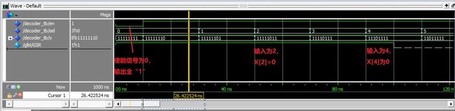
以一个3-8译码器为例,输入的真值表逻辑见下图,真值表逻辑是根据输入的数字X,输出Y中下标为值X的为1,其余为0,将X用二进制表示即为sel[2:0]的3比特。

设计文件代码
library IEEE;
use IEEE.STD_LOGIC_1164.ALL;
entity decoder is
GENERIC (n:integer := 8);
  Port (en:IN STD_LOGIC;
  sel:IN INTEGER RANGE 0 TO n-1 ;
  x:OUT STD_LOGIC_VECTOR (7 DOWNTO 0) );
end decoder;

architecture Behavioral of decoder is
begin
	PROCESS(en,sel)
		variable temp1:STD_LOGIC_VECTOR(x'high DOWNTO 0);
	begin
		temp1:=(others=>'1');
		if(en='1') then
			temp1(sel):='0';
		end if;
	x<=temp1;
	end process;
end Behavioral;
测试文件代码
library IEEE;
use IEEE.STD_LOGIC_1164.ALL;
use IEEE.STD_LOGIC_ARITH.ALL;
use IEEE.STD_LOGIC_UNSIGNED.ALL;

entity decoder_tb is
GENERIC (n:integer := 7);
end decoder_tb;

architecture Behavioral of decoder_tb is
component decoder is
	PORT(en:IN STD_LOGIC;
		sel:IN INTEGER RANGE 0 TO n;
		x:out std_logic_vector(7 downto 0));
end component decoder;

signal en:STD_LOGIC;
signal sel: INTEGER RANGE 0 TO n;
signal x:std_logic_vector(7 downto 0);
begin
dut:decoder port map(en=>en,sel=>sel,x=>x);
process
	begin
	en<='0';
	sel<=0;
	wait for 10ns;
	en<='1';
	wait for 20ns;
	sel<=1;
	wait for 20ns;
	sel<=2;
	wait for 20ns;
	sel<=3;
	wait for 20ns;
	sel<=4;
	wait for 20ns;
	sel<=5;
	wait for 20ns;
	sel<=6;
	wait for 20ns;
	sel<=7;
	wait ;
	end process;
end Behavioral;
综合结果,选择输入sel连接到8个LUT4,每个LUT4对应译码输出X中的一位,无时序逻辑单元触发器。

仿真结果,输出信号Y中对应索引值为sel的为0,符合预期
3.2 时序逻辑
时序逻辑选用触发器的设计进行示例,设计文件代码。
library IEEE;
use IEEE.STD_LOGIC_1164.ALL;

entity FF is
  Port (en,clk,d:IN STD_LOGIC;
  	q:OUT STD_LOGIC );
end FF;

architecture Behavioral of FF is
begin
	PROCESS(en,clk)
	begin
		if(en='0') then
			q<='0';
		else
		if clk'event and clk='1' then
			q<=d;
		end if;
		end if;
	end process;
end Behavioral;
测试文件代码
entity decoder_tb is
end decoder_tb;

architecture Behavioral of decoder_tb is
component FF is
  Port ( en,clk,d:IN STD_LOGIC;
  		q:out STD_LOGIC);
end component FF;
signal en:STD_LOGIC:='0';
signal clk:STD_LOGIC:='0';
signal d:STD_LOGIC:='0';
signal q:STD_LOGIC;
begin
dut:FF port map(en=>en,clk=>clk,d=>d,q=>q);

process
	constant period:Time:=10ns;
	begin
	clk<='1';
	wait for period/2;
	clk<='0';
	wait for period/2;
end process;
process
	begin
	en<='0';
	d<='1';
	wait for 30ns;
	en<='1';
	wait for 70ns;
	d<='0';
	wait for 30ns;
	d<='1';
	wait;
	end process;

end Behavioral;
综合结果:综合出一个FDCE

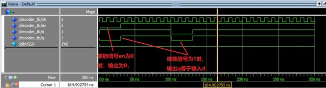
仿真结果:
四、常用编写
下面将介绍激励编写中常用到的描述
4.1 时钟信号
a)占空比为50%
constant PERIOD : time := ;  --定义时钟周期

--使用after语句
CLK <= not CLK after PERIOD/2;

--使用wait语句
constant PERIOD : time := ;
CLK <= '0';
wait for PERIOD/2;
CLK <= '1';
wait for PERIOD/2;
b)非50%占空比
constant DUTY_CYCLE : real := ; --定义占空比系数
constant PERIOD : time := ;  --定义时钟周期

--使用after语句
CLK <= '1' after (PERIOD - (PERIOD * DUTY_CYCLE)) when CLK = '0'
  else '0' after (PERIOD * DUTY_CYCLE);

--使用wait语句
CLK <= '0';
wait for (PERIOD - (PERIOD * DUTY_CYCLE));
CLK <= '1';
wait for (PERIOD * DUTY_CYCLE);
c)差分端口占空比为50%
constant PERIOD : time := ;   --设置时钟周期

--使用after语句
CLK_P <= not CLK_P after PERIOD/2;
CLK_N <= not CLK_N after PERIOD/2;
--使用wait语句
CLK_P <= '0';
CLK_N <= '1';
wait for PERIOD/2;
CLK_P <= '1';
CLK_N <= '0';
wait for PERIOD/2;
4.2 延时
a) 指定延时时间
constant SIM_TIME : time := 10 ms;  --设置仿真时间SIM_TIME, 时间为10ms
 <=  after SIM_TIME;  --信号在SIM_TIME后进行赋值

wait on ;   --延时到信号有变化

wait until falling_edge(); --延时到信号的下降沿到来

wait until rising_edge();  --延时到信号的上升沿到来

wait until  = ;   --延时到信号变化到指定值
4.3 循环
a) loop语句
loop
   CLK <= not CLK;
   wait for PERIOD/2;
   if  then
      exit;
   end if;
end loop;
b) for语句
for  in  to  loop
   ;
   ;
end loop;
c)while语句
while  loop
   ;
   ;
end loop;
4.4 进程
a) 组合逻辑
process (所有的输入信号,信号间用逗号隔开)
begin
   ;
end process;
b)时序逻辑
时钟下降沿触发,异步复位
process (,)
begin
   if  = '1' then
      ;
   elsif ('event and  = '0') then
      if  = '1' then
         ;
      else
         ;
      end if;
   end if;
end process;
时钟下降沿触发,同步置位
process ()
begin
   if ('event and  = '0'>) then
      if  = '1' then
         ;
      else
         ;
      end if;
   end if;
end process;
时钟上升沿触发,异步复位
process (,)
begin
   if  = '1' then
      ;
   elsif ('event and  = '1') then
      if  = '1' then
         ;
      else
         ;
      end if;
   end if;
end process;
时钟上升沿触发,同步复位
process ()
begin
   if ('event and  = '1'>) then
      if  = '1' then
         ;
      else
         ;
      end if;
   end if;
end process;