CAD 中Spline(样条曲线)的创建
我把自己研究的流程留下,读者需慢慢探索:
Polyline pl = new Polyline();
pl.AddVertexAt(0, new Point2d(2, 2), 0, 0, 0);
pl.AddVertexAt(1, new Point2d(5, 5), 0, 0, 0);
pl.AddVertexAt(2, new Point2d(10, 3), 0, 0, 0);
pl.AddVertexAt(3, new Point2d(15, 10), 0, 0, 0);
Spline spline2 = new Spline();
spline2.InsertFitPointAt(0, new Point3d(2, 2, 2));
spline2.InsertFitPointAt(1, new Point3d(5, 5, 2));
spline2.InsertFitPointAt(2, new Point3d(10, 3, 2));
spline2.InsertFitPointAt(3, new Point3d(15, 10, 2));
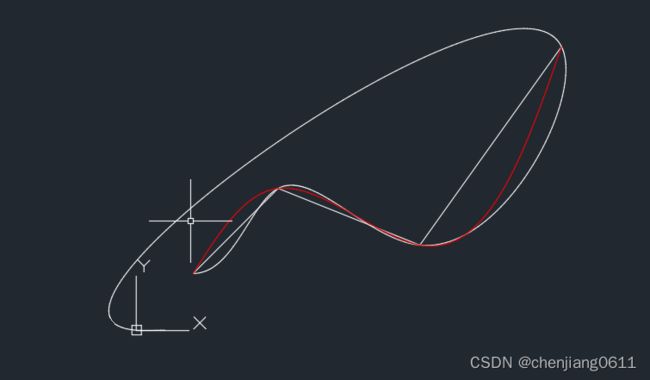
如果把上面的两个实体(pl和spline2)加入模型空间,发现和我们自己画的还是有区别,如下图:
发现差别很大,红色的样条曲线spline是我自己用cad的菜单所画;
差别1:连拟合的点的个数都不一致,上面代码明显在最后多了一个点那就线解决这个问题;
通过调试发现,Spline spline2 = new Spline()的时候就已经有两个点了,插入第一个点,还是两个点,但是插入第二个点的时候就是三个点了,看看类的API,还有一个函数SetFitPointAt,,
把上面代码改为如下:
Spline spline2 = new Spline();
spline2.SetFitPointAt(0, new Point3d(2, 2, 2));
spline2.SetFitPointAt(0, new Point3d(15, 10, 2));
spline2.InsertFitPointAt(1, new Point3d(5, 5, 2));
spline2.InsertFitPointAt(2, new Point3d(10, 3, 2));
效果如下图:
发现差别还是很大,红色的样条曲线spline是我自己用cad的菜单所画;
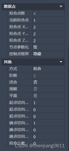
咋回事呢?下一步我才用了自己常用的方法,就是对比属性:
大家看到区别了吗,,起点切向... 画的一个是0,代码加上的是1,于是我手动改了一下数据,把1改为0, 在把“端点切向...”也改为0,,果然有效!!!!,,但是查看spline对象的属性里面并没有这个可以直接改。
把spline对象的API看,甚至把Curve的API都重新看了,,只有一个有点点像,
public ErrorStatus ModifyPositionAndTangent(double param, Point3d point, Vector3d deriv);
Tangent好像就是“切”的意思,所有编程特别的看外国的api,英语好还是有优势,不好也要时时积累
分析分析参数:
param 这个如果熟悉Curve或则polyline的应该知道,就是沿着起点走param那么长的位置
point 就是点位置,我们要改的肯定是起点和端点,
deriv 向量,有x,y,z组成,上面的代码默认是(1,0,0)了;
修改上面代码如下:
Spline spline2 = new Spline();
spline2.SetFitPointAt(0, new Point3d(2, 2, 2));
spline2.SetFitPointAt(1, new Point3d(15, 10, 2));
double para = spline2.GetParameterAtPoint(new Point3d(15, 10, 2));
spline2.ModifyPositionAndTangent(0, new Point3d(2, 2, 2), new Vector3d(0, 0, 0));
spline2.ModifyPositionAndTangent(para, new Point3d(15, 10, 2), new Vector3d(0, 0, 0));
spline2.InsertFitPointAt(1, new Point3d(5, 5, 2));
spline2.InsertFitPointAt(2, new Point3d(10, 3, 2));
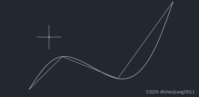
效果如下图:
终于和我想要的差不多了,,
接下来在看看构造函数之一:
public Spline(Point3dCollection fitPoints, Vector3d startTangent, Vector3d endTangent, KnotParameterizationEnum knotParam, int degree, double fitTolerance);
分析分析参数:
fitPoints 这个就是点集合,感觉把我的四个点传入就好
startTangent 开始切向量,传(0,0,0)
endTangent 结束切向量,传(0,0,0) 这连个参数感觉能实现上面改(切数据的功能)
knotParam 枚举(节点参数化),认识knot(节点)就简单了,我们传Chord
fitTolerance拟合公差,数学的概率论经常出现Tolerance这个词,,传0,,
修改代码如下:
Point3dCollection point3Ds = new Point3dCollection();
point3Ds.Add(new Point3d(2, 2, 3));
point3Ds.Add(new Point3d(5, 5, 3));
point3Ds.Add(new Point3d(10, 3, 3));
point3Ds.Add(new Point3d(15, 10, 3));
Spline spline3 = new Spline(point3Ds, new Vector3d(0, 0, 0), new Vector3d(0, 0, 0),
KnotParameterizationEnum.Chord, 3, 0);
结果就不用说了,和上面一样!
此次个人总结和分享就到此为止了!


