嵌入式Linux应用开发-第七章-RK3288和 RK3399的 LED驱动程序
嵌入式Linux应用开发-第七章-RK3288和 RK3399的 LED驱动程序
- RK3288和 RK3399的 LED驱动程序
-
- 7.3 RK3288和 RK3399的 LED驱动程序
-
- 7.3.1 原理图
-
- 7.3.1.1 fireflye RK3288的 LED原理图
- 7.3.1.2 firefly RK3399的 LED原理图
- 7.3.2 所涉及的寄存器操作
-
- 7.3.2.1 RK3288的 GPIO8_A1引脚
- 7.3.2.2 RK3399的 GPIO2_D3引脚
- 7.3.3 写程序
-
- 7.3.3.1 RK3288
- 7.3.3.2 RK3399
- 7.3.4 上机实验
-
- 7.3.4.1 RK3288
- 7.3.4.2 RK3399
- 7.3.5 课后作业
RK3288和 RK3399的 LED驱动程序

7.3 RK3288和 RK3399的 LED驱动程序
7.3.1 原理图
7.3.1.1 fireflye RK3288的 LED原理图
RK3288开发板上有 2个 LED,原理图如下,其中的 WORK_LED使用引脚 GPIO8_A1:

这些 LED引脚输出低电平时,LED被点亮;输出高电平时,LED被熄灭。
7.3.1.2 firefly RK3399的 LED原理图
RK3399开发板上有 3个 LED,原理图如下,其中的 WORK_LED使用引脚 GPIO2_D3:

这些 LED引脚输出低电平时,LED被点亮;输出高电平时,LED被熄灭。
7.3.2 所涉及的寄存器操作
截图便于对比,后面有文字便于复制:

7.3.2.1 RK3288的 GPIO8_A1引脚
a. 使能 GPIO8

设置 CRU_CLKGATE14_CON的 b[8]为 0使能 GPIO8,要修改 b[8]的前提是把 b[24]设置为 1。
 /* rk3288 GPIO8_A1 */
  /* a. 使能 GPIO8
  * set CRU to enable GPIO8
  * CRU_CLKGATE14_CON 0xFF760000 + 0x198
  * (1<<(8+16)) | (0<<8)
  */
b. 设置 GPIO8_A1用于 GPIO

设置 GRF_GPIO8A_IOMUX的 b[3:2]为 0b00把 GPIO8_A1用作 GPIO,要修改 b[3:2]的前提是把 b[19:18]设置为 0b11。
 /* b. 设置 GPIO8_A1用于 GPIO
 * set PMU/GRF to configure GPIO8_A1 as GPIO
 * GRF_GPIO8A_IOMUX 0xFF770000 + 0x0080
 *  bit[3:2] = 0b00
 *  (3<<(2+16)) | (0<<2)
 * /
c. 设置 GPIO8_A1作为 output引脚

设置 GPIO_SWPORTA_DDR 寄存器 b[1]为 1,把 GPIO8_A1设置为输出引脚。 注意: GPIO_A0~A7 对应 bit0bit7;GPIO_B0B7 对应 bit8~bit15;
GPIO_C0~C7 对应 bit16bit23;GPIO_D0D7 对应 bit24~bit31
/* c. 设置 GPIO8_A1作为 output引脚
* set GPIO_SWPORTA_DDR to configure GPIO8_A1 as output
*  GPIO_SWPORTA_DDR 0xFF7F0000 + 0x0004
* bit[1] = 0b1
* /
d. 设置 GPIO8_A1输出高电平
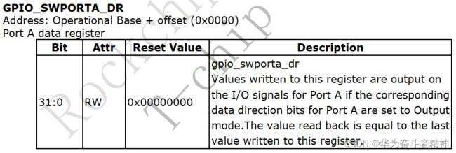
设置 GPIO_SWPORTA_DR 寄存器 b[1]为 1,让 GPIO8_A1输出高电平。
注意:
GPIO_A0~A7 对应 bit0bit7;GPIO_B0B7 对应 bit8~bit15;
GPIO_C0~C7 对应 bit16bit23;GPIO_D0D7 对应 bit24~bit31
/* d. 设置 GPIO8_A1输出高电平
* set GPIO_SWPORTA_DR to configure GPIO8_A1 output 1
*  GPIO_SWPORTA_DR 0xFF7F0000 + 0x0000
*  bit[1] = 0b1
* /
e. 设置 GPIO8_A1输出低电平
同样是设置 GPIO_SWPORTA_DR 寄存器,把 b[1]设为 0,让 GPIO8_A1输出低电平。
/* e. 设置 GPIO8_A1输出低电平
* set GPIO_SWPORTA_DR to configure GPIO8_A1 output 0
*  GPIO_SWPORTA_DR 0xFF7F0000 + 0x0000
*  bit[1] = 0b0
* /
7.3.2.2 RK3399的 GPIO2_D3引脚
a. 使能 GPIO2

设置 CRU_CLKGATE_CON31的 b[3]为 0使能 GPIO2,要修改 b[3]的前提是把 b[19]设置为 1。
 /* rk3399 GPIO2_D3 */
 /* a. 使能 GPIO2  * set CRU to enable GPIO2
 * CRU_CLKGATE_CON31 0xFF760000 + 0x037c
 * (1<<(3+16)) | (0<<3)
 */
b. 设置 GPIO2_D3用于 GPIO
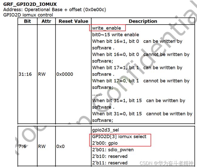
设置 GRF_GPIO2D_IOMUX的 b[7:6]为 0b00把 GPIO2_D3用作 GPIO,要修改 b[7:6]的前提是把 b[23:22]设置为 0b11。
/* b. 设置 GPIO2_D3用于 GPIO
* set PMU/GRF to configure GPIO2_D3 as GPIO
*  GRF_GPIO2D_IOMUX 0xFF770000 + 0x0e00c
*  bit[7:6] = 0b00  * (3<<(6+16)) | (0<<6)
* /
c. 设置 GPIO2_D3作为 output引脚

设置 GPIO_SWPORTA_DDR 寄存器 b[27]为 1,把 GPIO2_D3设置为输出引脚。
注意:
GPIO_A0~A7 对应 bit0bit7;GPIO_B0B7 对应 bit8~bit15;
GPIO_C0~C7 对应 bit16bit23;GPIO_D0D7 对应 bit24~bit31
/* c. 设置 GPIO2_D3作为 output引脚
* set GPIO_SWPORTA_DDR to configure GPIO2_D3 as output
 * GPIO_SWPORTA_DDR 0xFF780000 + 0x0004
 *  bit[27] = 0b1
 * /
d. 设置 GPIO2_D3输出高电平

设置 GPIO_SWPORTA_DR 寄存器 b[27]为 1,让 GPIO2_D3输出高电平。
注意:
GPIO_A0~A7 对应 bit0bit7;GPIO_B0B7 对应 bit8~bit15;
GPIO_C0~C7 对应 bit16bit23;GPIO_D0D7 对应 bit24~bit31
  /* d. 设置 GPIO2_D3输出高电平
  * set GPIO_SWPORTA_DR to configure GPIO2_D3 output 1
  * GPIO_SWPORTA_DR 0xFF780000 + 0x0000
  *  bit[27] = 0b1
  */
e. 设置 GPIO2_D3输出低电平
同样是设置 GPIO_SWPORTA_DR 寄存器,把 b[27]设为 0,让 GPIO2_D3输出低电平。
 /* e. 设置 GPIO2_D3输出低电平
 * set GPIO_SWPORTA_DR to configure GPIO2_D3 output 0
 *  GPIO_SWPORTA_DR 0xFF780000 + 0x0000
 *  bit[27] = 0b0
 * /
7.3.3 写程序
7.3.3.1 RK3288
使用 GIT下载所有源码后,本节源码位于如下目录:
01_all_series_quickstart\
05_嵌入式 Linux驱动开发基础知识\source\02_led_drv\
02_led_drv_for_boards\rk3288_src_bin
硬件相关的文件是 board_rk3288.c,其他文件跟 LED框架驱动程序完全一样。 它首先构造了一个 led_operations结构体,用来表示 LED的硬件操作:
91 static struct led_operations board_demo_led_opr = {
92      .num  = 1,
93      .init = board_demo_led_init,
94      .ctl  = board_demo_led_ctl,
95 };
96
led_operations结构体中有 init函数指针,它指向 board_demo_led_init函数,在里面将会初始化LED引脚:使能、设置为 GPIO模式、设置为输出引脚。
值得关注的是第 32~35行,对于寄存器要先使用 ioremap得到它的虚拟地址,以后使用虚拟地址访问寄存器:
 20 static volatile unsigned int *CRU_CLKGATE14_CON;
 21 static volatile unsigned int *GRF_GPIO8A_IOMUX ;
 22 static volatile unsigned int *GPIO8_SWPORTA_DDR;
 23 static volatile unsigned int *GPIO8_SWPORTA_DR ;
 24
 25 static int board_demo_led_init (int which) /* 初始化 LED, which-哪个 LED */
 26 {
 27      //printk("%s %s line %d, led %d\n", __FILE__, __FUNCTION__, __LINE__, which);
 28      if (which == 0)
 29      {
 30              if (!CRU_CLKGATE14_CON)
 31              {
 32                      CRU_CLKGATE14_CON = ioremap(0xFF760000 + 0x0198, 4);
 33                      GRF_GPIO8A_IOMUX  = ioremap(0xFF770000 + 0x0080, 4);
 34                      GPIO8_SWPORTA_DDR = ioremap(0xFF7F0000 + 0x0004, 4);
 35                      GPIO8_SWPORTA_DR  = ioremap(0xFF7F0000 + 0x0000, 4);
 36              }
 37
 38              /* rk3288 GPIO8_A1 */
 39              /* a. 使能 GPIO8
 40               * set CRU to enable GPIO8
 41               * CRU_CLKGATE14_CON 0xFF760000 + 0x198
 42               * (1<<(8+16)) | (0<<8)
 43               */
 44              *CRU_CLKGATE14_CON = (1<<(8+16)) | (0<<8);
 45
 46              /* b. 设置 GPIO8_A1用于 GPIO
 47               * set PMU/GRF to configure GPIO8_A1 as GPIO
 48               * GRF_GPIO8A_IOMUX 0xFF770000 + 0x0080
 49               * bit[3:2] = 0b00
 50               * (3<<(2+16)) | (0<<2)
 51               */
 52              *GRF_GPIO8A_IOMUX =(3<<(2+16)) | (0<<2);
 53
 54              /* c. 设置 GPIO8_A1作为 output引脚
 55               * set GPIO_SWPORTA_DDR to configure GPIO8_A1 as output
56               * GPIO_SWPORTA_DDR 0xFF7F0000 + 0x0004
57               * bit[1] = 0b1
58               */
59              *GPIO8_SWPORTA_DDR |= (1<<1);
60      }
61              return 0;
62 }
63
led_operations结构体中有 ctl函数指针,它指向 board_demo_led_ctl函数,在里面将会根据参数设置 LED引脚的输出电平:
64 static int board_demo_led_ctl (int which, char status) /* 控制 LED, which-哪个 LED, status:1-亮, 0-灭*/
65 {
66      //printk("%s %s line %d, led %d, %s\n", __FILE__, __FUNCTION__, __LINE__, which, status ? "on" : "off");
67      if (which == 0)
68      {
69              if (status) /* on: output 0 */
70              {
71                      /* e. 设置 GPIO8_A1输出低电平
72                       * set GPIO_SWPORTA_DR to configure GPIO8_A1 output 0
73                       * GPIO_SWPORTA_DR 0xFF7F0000 + 0x0000
74                       * bit[1] = 0b0
75                       */
76                      *GPIO8_SWPORTA_DR &= ~(1<<1);
77              }
78              else /* off: output 1 */
79              {
80                      /* d. 设置 GPIO8_A1输出高电平
81                       * set GPIO_SWPORTA_DR to configure GPIO8_A1 output 1
82                       * GPIO_SWPORTA_DR 0xFF7F0000 + 0x0000
83                       * bit[1] = 0b1
84                       */
85                      *GPIO8_SWPORTA_DR |= (1<<1);
86              }
87      }
88      return 0;
89 }
90
下面的 get_board_led_opr函数供上层调用,给上层提供 led_operations结构体:
97 struct led_operations *get_board_led_opr(void)
98 {
99      return &board_demo_led_opr;
100 }
101
7.3.3.2 RK3399
使用 GIT下载所有源码后,本节源码位于如下目录:
01_all_series_quickstart\
05_嵌入式 Linux驱动开发基础知识\source\02_led_drv\
02_led_drv_for_boards\rk3399_src_bin
硬件相关的文件是 board_rk3399.c,其他文件跟 LED框架驱动程序完全一样。 它首先构造了一个 led_operations结构体,用来表示 LED的硬件操作:
91 static struct led_operations board_demo_led_opr = {
92     .num  = 1,
93     .init = board_demo_led_init,
94     .ctl  = board_demo_led_ctl,
95 };
96
led_operations结构体中有 init函数指针,它指向 board_demo_led_init函数,在里面将会初始化LED引脚:使能、设置为 GPIO模式、设置为输出引脚。
值得关注的是第 32~35行,对于寄存器要先使用 ioremap得到它的虚拟地址,以后使用虚拟地址访问寄存器:
20 static volatile unsigned int *CRU_CLKGATE_CON31;
21 static volatile unsigned int *GRF_GPIO2D_IOMUX ;
22 static volatile unsigned int *GPIO2_SWPORTA_DDR;
23 static volatile unsigned int *GPIO2_SWPORTA_DR ;
24
25 static int board_demo_led_init (int which) /* 初始化 LED, which-哪个 LED */
26 {
27     //printk("%s %s line %d, led %d\n", __FILE__, __FUNCTION__, __LINE__, which);
28     if (which == 0)
29     {
30         if (!CRU_CLKGATE_CON31)
31         {
32             CRU_CLKGATE_CON31 = ioremap(0xFF760000 + 0x037c, 4);
33             GRF_GPIO2D_IOMUX  = ioremap(0xFF770000 + 0x0e00c, 4);
34             GPIO2_SWPORTA_DDR = ioremap(0xFF780000 + 0x0004, 4);
35             GPIO2_SWPORTA_DR  = ioremap(0xFF780000 + 0x0000, 4);
36         }
37
38         /* rk3399 GPIO2_D3 */
39         /* a. 使能 GPIO2 40          * set CRU to enable GPIO2
41          * CRU_CLKGATE_CON31 0xFF760000 + 0x037c
42          * (1<<(3+16)) | (0<<3)
43          */
44         *CRU_CLKGATE_CON31 = (1<<(3+16)) | (0<<3);
45
46         /* b. 设置 GPIO2_D3用于 GPIO
47          * set PMU/GRF to configure GPIO2_D3 as GPIO
48          * GRF_GPIO2D_IOMUX 0xFF770000 + 0x0e00c
49          * bit[7:6] = 0b00
50          * (3<<(6+16)) | (0<<6)
51          */
52         *GRF_GPIO2D_IOMUX = (3<<(6+16)) | (0<<6);
53
54         /* c. 设置 GPIO2_D3作为 output引脚
55          * set GPIO_SWPORTA_DDR to configure GPIO2_D3 as output
56          * GPIO_SWPORTA_DDR 0xFF780000 + 0x0004
57          * bit[27] = 0b1
58          */
59         *GPIO2_SWPORTA_DDR |= (1<<27);
60     }
61     return 0;
62 }
63
led_operations结构体中有 ctl函数指针,它指向 board_demo_led_ctl函数,在里面将会根据参数设置 LED引脚的输出电平:
64 static int board_demo_led_ctl (int which, char status) /* 控制 LED, which-哪个 LED, status:1-亮, 0-灭*/
65 {
66     //printk("%s %s line %d, led %d, %s\n", __FILE__, __FUNCTION__, __LINE__, which, status ? "on" : "off");
67     if (which == 0)
68     {
69         if (status) /* on: output 1 */
70         {
71             /* d. 设置 GPIO2_D3输出高电平
72              * set GPIO_SWPORTA_DR to configure GPIO2_D3 output 1
73              * GPIO_SWPORTA_DR 0xFF780000 + 0x0000
74              * bit[27] = 0b1
75              */
76             *GPIO2_SWPORTA_DR |= (1<<27);
77         }
78         else /* off : output 0 */
79         {
80             /* e. 设置 GPIO2_D3输出低电平
81              * set GPIO_SWPORTA_DR to configure GPIO2_D3 output 0
82              * GPIO_SWPORTA_DR 0xFF780000 + 0x0000
83              * bit[27] = 0b0
84              */
85             *GPIO2_SWPORTA_DR &= ~(1<<27);
86         }
87     }
88     return 0;
89 }
90
下面的 get_board_led_opr函数供上层调用,给上层提供 led_operations结构体:
97 struct led_operations *get_board_led_opr(void)
98 {
99     return &board_demo_led_opr;
100 }
101
7.3.4 上机实验
首先设置工具链,然后修改驱动程序 Makefile指定内核源码路径,就可以编译驱动程序和测试程序了。 启动开发板,挂载 NFS文件系统,这样就可以访问到 Ubuntu中的文件。 最后,就可以在开发板上进行下列测试。
7.3.4.1 RK3288
# insmod  xxxxxx_led.ko
# ./ledtest  /dev/xxxxxx_led0  on
# ./ledtest  /dev/xxxxxx_led0  off
7.3.4.2 RK3399
要先禁止内核中原来的 LED驱动,把“heatbeat”功能关闭,执行以下命令即可:
# echo none > /sys/class/leds/firefly\:yellow\:heartbeat/trigger
# echo none > /sys/class/leds/firefly\:yellow\:user/trigger
# echo none > /sys/class/leds/firefly\:red\:power/trigger
这样就可以使用我们的驱动程序做实验了:
 # insmod  xxxxxx_led.ko
 # ./ledtest  /dev/xxxxxx_led0  on
 # ./ledtest  /dev/xxxxxx_led0  off
如果想恢复原来的心跳功能,可以执行:
# echo heartbeat > /sys/class/leds/firefly\:yellow\:heartbeat/trigger
# echo heartbeat > /sys/class/leds/firefly\:yellow\:user/trigger
# echo heartbeat > /sys/class/leds/firefly\:red\:power/trigger
7.3.5 课后作业
a. 在驱动里有 ioremap,什么时候执行 iounmap?请完善程序
b. 视频里我们只实现了点一个 LED,请修改代码实现操作所有 LED