STM32的USART外设
STM32的USART外设
- STM32USART的简介
- STM32USART的使用
-
- 连接图
- 初始化流程
- 常用库函数
- 初始化USART函数代码
- USART发送数据代码
- STM32串口发送全代码
STM32USART的简介
USART(Universal Synchronous/Asynchronous Receiver/Transmitter)通用同步/异步收发器
如果是UART就是没有Synchronous同步模式,我们不是很常用同步模式。
USART是STM32内部集成的硬件外设,可根据数据寄存器的一个字节数据自动生成数据帧时序,从TX引脚发送出去,也可自动接收RX引脚的数据帧时序,拼接为一个字节数据,存放在数据寄存器里。
这就是USART的功能,直接读写寄存器,就可以发射接收数据,USART会自行创造波形和分析波形,就不需要我们一位一位的去翻译每个电平代表的数据。
SUART配置
- 支持同步模式、硬件流控制、DMA、智能卡、IrDA、LIN
- 自带波特率发生器,最高达4.5Mbits/s
自带波特率发生器,最高达4.5Mbits/s
常用9600和115200
可配置数据位长度(8/9)这里的数据位长度是包含校验位的,所以不需要校验则8位,需要校验则9位、停止位长度(0.5/1/1.5/2)
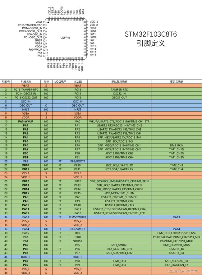
STM32F103C8T6 USART资源: USART1、 USART2、 USART3
其中USART1在APB2上,其他两个在APB1上
STM32USART的使用
连接图
- USART1的TX与RX在PA09和PA10上
- USART2在PA02和PA03
- USART3在PB10和PB11上
要根据USART1,2,3,连结STM32上不同的引脚,例如现在我使用UASTR1就使用的是A9 A10两个引脚

注意的是USB模块的TX要接到STM32的RX,RX接到STM32的TX。这点在使用很多外设时候都要注意
初始化流程
- 需要将USART的时钟和GPIO的时钟打开
- GPIO初始化,把输出TX的GPIO配置成复用输出模式,输入RX的GPIO配置成输入模式。
- 配置USART,跟GPIO有一些像,使用一个结构体将USART的功能配置好。注意这里我们在接收数据时候可能要配置好一个中断,所以要把ITConfg和NVIC的代码配置好。
常用库函数
我们使用库函数进行配置就不需要对寄存器进行一个一个的数据配置了。
-
void USART_DeInit(USART_TypeDef* USARTx);将某一个USART寄存器重置为默认值
例如void USART_DeInit(USART1); -
初始化
void USART_Init(USART_TypeDef* USARTx, USART_InitTypeDef* USART_InitStruct)根据结构体的参数配置来对USARTx外设进行初始化
例如我们配置USART1USART_Init(USART1,&USART_InitStructure);
这里的USART_InitStructure就如同GPIO的GPIO_InitStructured一样,是一个包含了各种参数的结构体 -
填充使用
void USART_StructInit(USART_InitTypeDef* USART_InitStruct)
这个函数的作用是将USART_InitStructure结构体变量成员按默认值填充
例如USART_StructInit(&USART_InitStructure);就是将USART_InitStructure这个包含了各种参数的结构体按照默认值进行填充配置 -
配置时钟使用
void USART_ClockInit(USART_TypeDef* USARTx,USART_ClockInitTypeDef*USART_ClockInitStruct)
voidUSART_ClockStructInit(USART_ClockInitTypeDef*USART_ClockInitStruct)
这两个函数是用来配置同步时钟输出的,根据USART_ClockInitStruct中的指定参数初始化USARTx的外围时钟。包括时钟是不是要输出,时钟的极性与相位等。 -
void USART_Cmd(USART_TypeDef* USARTx, FunctionalState NewState)
使能或者失能USART外设
例如 USART_Cmd(USART1 , ENABLE);
意思是将USART1打开 -
同样
void USART_ITConfig(USART_TypeDef* USARTx, uint16_t USART_IT, FunctionalState NewState)
配置指定的USART中断
例如USART_ITConfig(USART1 ,USART_IT_RXNE , ENABLE);
就是将USART1中断 -
还有两个很重要的发送和接收函数
void USART_SendData(USART_TypeDef* USARTx, uint16_t Data)
uint16_t USART_ReceiveData(USART_TypeDef* USARTx)
初始化USART函数代码
void Serial_Init(void)
{
	RCC_APB2PeriphClockCmd(RCC_APB2Periph_USART1, ENABLE);
	RCC_APB2PeriphClockCmd(RCC_APB2Periph_GPIOA, ENABLE);
	//将GPIOA和USART1两个外设的时钟打开

	GPIO_InitTypeDef GPIO_InitStructure;
	GPIO_InitStructure.GPIO_Mode = GPIO_Mode_AF_PP;
	GPIO_InitStructure.GPIO_Pin = GPIO_Pin_9;
	GPIO_InitStructure.GPIO_Speed = GPIO_Speed_50MHz;
	GPIO_Init(GPIOA, &GPIO_InitStructure);
	//将GPIO的引脚9配置成输出模式,因为用这个脚做输出用

	USART_InitTypeDef USART_InitStructure;
	USART_InitStructure.USART_BaudRate = 9600;//设置波特率
	USART_InitStructure.USART_HardwareFlowControl = USART_HardwareFlowControl_None;//不开启流控制
	USART_InitStructure.USART_Mode = USART_Mode_Tx;//模式为输出
	USART_InitStructure.USART_Parity = USART_Parity_No;//无校验位
	USART_InitStructure.USART_StopBits = USART_StopBits_1;//停止位设置为1
	USART_InitStructure.USART_WordLength = USART_WordLength_8b;//因为无校验位我们传输8位数据
	USART_Init(USART1, &USART_InitStructure);
	//这里做如同GPIO一样做结构体的参数配置

	USART_Cmd(USART1, ENABLE);
	//开启USART1
}
USART发送数据代码
因为库函数中只给了我们传输一个字节的函数:void USART_SendData(USART_TypeDef* USARTx, uint16_t Data)所以需要我们自行编写一些传输数字,数组,字符串等函数,封装好便于模块化编程。
发送字节
void Serial_SendByte(uint8_t Byte)
{
	USART_SendData(USART1, Byte);
	while (USART_GetFlagStatus(USART1, USART_FLAG_TXE) == RESET);
}
发送数组
void Serial_SendArray(uint8_t *Array, uint16_t Length)
{
	uint16_t i;
	for (i = 0; i < Length; i ++)
	{
		Serial_SendByte(Array[i]);
	}
}
发送字符串
void Serial_SendString(char *String)
{
	uint8_t i;
	for (i = 0; String[i] != '\0'; i ++)
	{
		Serial_SendByte(String[i]);
	}
}
STM32串口发送全代码
#include "stm32f10x.h"                  // Device header
#include "Delay.h"
#include "OLED.h"
#include "Serial.h"

int main(void)
{
	OLED_Init();

	Serial_Init();

	Serial_SendByte(0x41);
	// 发送单个字节数据

	uint8_t MyArray[] = {0x42, 0x43, 0x44, 0x45};
	Serial_SendArray(MyArray, 4);
	// 发送一个4位的数组

	Serial_SendString("\r\nNum1=");
	// 换行后发送Num1=字符串

	Serial_SendNumber(111, 3);
	//发送一个长度为3的数字111

	printf("\r\nNum2=%d", 222);
	//通过移植print函数进行数据的打印,打印效果为Num2=222,具体移植打印方法待我补充
	//下面代码同理都是移植print函数

	char String[100];
	sprintf(String, "\r\nNum3=%d", 333);
	Serial_SendString(String);

	Serial_Printf("\r\nNum4=%d", 444);
	Serial_Printf("\r\n");

	while (1)
	{

	}
}
