HDL4SE:软件工程师学习Verilog语言(四)
4 模拟器
总是不能运行一个应用程序,对学习语言是致命的,一个Hello, World!级别的应用就这么复杂,时间长了会把人的耐心磨尽。因此本节我们先暂停对verilog语言的学习,来讨论模拟器的实现,试图给出一个初步的实现,至少能够完成前面一节中给出的应用。当然,编译器还没有那么快,我们就用手工编译好了,好在这个应用的逻辑不算复杂,手工编译(相当于c语言下写汇编)也还是可以接受的,顺便也看看编译器要输出什么样的结果,模拟器才能接受并运行。
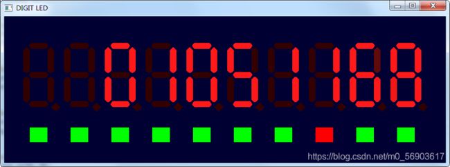
本节经过努力,终于让例子在模拟器上跑起来了,可以在windows和linux上编译运行,按说在Mac上也应该可以,没有进行更多的测试了。这是跑的界面,使用F1–F10来模拟10个按键,按键的状态绘制在数码管下面,红色表示按下,绿色表示弹起,实际实现时,通过按F1–F10来切换按下和弹起,F3按下才会计数:
下面是实际跑起来的画面,左边是Windows,右边是Linux,中间的显示器接到Linux上:

本节中有大段大段的代码,建议用电脑看效果好一些,最好按照后面的指引将代码下载一下来编译运行,体会一下其中的运行过程。
我们首先还是先用verilog语言把前面的应用做完,然后再讨论如何运行它。
4.1 译码器的实现
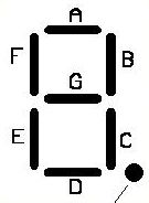
前面我们已经有了主模块,计数器模块,现在还差一个译码模块,就是把计数值翻译到数码管的控制信号。前面说到,一个数码管靠8个位来控制,ABCDEFG,小数点分别对应其中的第0位到第7位。每一位为1就点亮对应的LED段,0则不点亮。我们这个应用中只显示计数值,因此小数点是不用的,可以一直设置为0,一个数码管显示一个10进制数字,对应关系如下(如果输入不是一个十进制数字,我们可以显示一个E,表示出错了):
| N | DP | G | F | E | D | C | B | A | V |
|---|---|---|---|---|---|---|---|---|---|
| 0 | 0 | 0 | 1 | 1 | 1 | 1 | 1 | 1 | 8’b00111111 |
| 1 | 0 | 0 | 0 | 0 | 0 | 1 | 1 | 0 | 8’b00000110 |
| 2 | 0 | 1 | 0 | 1 | 1 | 0 | 1 | 1 | 8’b01011011 |
| 3 | 0 | 1 | 0 | 0 | 1 | 1 | 1 | 1 | 8’b01001111 |
| 4 | 0 | 1 | 1 | 0 | 0 | 1 | 1 | 0 | 8’b01100110 |
| 5 | 0 | 1 | 1 | 0 | 1 | 1 | 0 | 1 | 8’b01101101 |
| 6 | 0 | 1 | 1 | 1 | 1 | 1 | 0 | 1 | 8’b01111101 |
| 7 | 0 | 0 | 0 | 0 | 0 | 1 | 1 | 1 | 8’b00000111 |
| 8 | 0 | 1 | 1 | 1 | 1 | 1 | 1 | 1 | 8’b01111111 |
| 9 | 0 | 1 | 1 | 0 | 1 | 1 | 1 | 1 | 8’b01101111 |
| E | 0 | 1 | 1 | 1 | 1 | 0 | 0 | 1 | 8’b01111001 |
如果用c语言写,这个是比较简单的,一个switch语句就搞定了。verilog中有对应的语句,就是case语句,具体的语法以及如何编译的讨论我们后面的章节再详细介绍。这里先直接用着,软件工程师靠猜也该知道怎么回事:
module dec2seg(input [3:0] dec, output [7:0] seg);
wire [3:0] dec;
reg [7:0] seg;
always @(dec)
  case (dec)
    4'd0:seg = 8'b00111111;
    4'd1:seg = 8'b00000110;
    4'd2:seg = 8'b01011011;
    4'd3:seg = 8'b01001111;
    4'd4:seg = 8'b01100110;
    4'd5:seg = 8'b01101101;
    4'd6:seg = 8'b01111101;
    4'd7:seg = 8'b00000111;
    4'd8:seg = 8'b01111111;
    4'd9:seg = 8'b01101111;
    default:seg = 8'b01111001;
  endcase
endmodule
这个实现看着很简洁,case语句可以用两种方式表示,一种是编译成一个多路选择器外加11个常数基本单元,另一种对返回都是常数的多路选择器干脆编译成一个ROM。
我们先来考虑基本单元如何表示,如何在我们的模拟系统中表达出来。
4.2 基本单元的表达及系统库
每个FPGA或ASIC都有自己的基本单元库。比较复杂的基本单元,开发工具还提供所谓的IP生成工具来根据用户的配置参数生成代码,这些代码可以是verilog代码,其中包括完整的逻辑实现,还能够设置包括一些时序参数以供仿真工具进行仿真,还有一些额外的信息用来指导编译工具(综合工具)如何连接到硬件实现的基本单元上去。常见的比如RAM,FIFO,DSP单元等等。比如下面的verilog代码,就是Altera(被Intel收购了)的FPGA开发工具Quartus II生成的一个8位16选一的多路选择器:
/*
前面有一大段注释,大概是说这个模块的名称是 LPM_MUX
模拟库在lpm中。有些综合工具似乎把综合工具使用的一些
提示信息放在注释中。
*/
// synopsys translate_off
`timescale 1 ps / 1 ps
// synopsys translate_on
module mux4x8 (
	data0x,
	data10x,
	data11x,
	data12x,
	data13x,
	data14x,
	data15x,
	data1x,
	data2x,
	data3x,
	data4x,
	data5x,
	data6x,
	data7x,
	data8x,
	data9x,
	sel,
	result);

	input	[7:0]  data0x;
	input	[7:0]  data10x;
	input	[7:0]  data11x;
	input	[7:0]  data12x;
	input	[7:0]  data13x;
	input	[7:0]  data14x;
	input	[7:0]  data15x;
	input	[7:0]  data1x;
	input	[7:0]  data2x;
	input	[7:0]  data3x;
	input	[7:0]  data4x;
	input	[7:0]  data5x;
	input	[7:0]  data6x;
	input	[7:0]  data7x;
	input	[7:0]  data8x;
	input	[7:0]  data9x;
	input	[3:0]  sel;
	output	[7:0]  result;

	wire [7:0] sub_wire0;
	wire [7:0] sub_wire17 = data15x[7:0];
	wire [7:0] sub_wire16 = data14x[7:0];
	wire [7:0] sub_wire15 = data13x[7:0];
	wire [7:0] sub_wire14 = data12x[7:0];
	wire [7:0] sub_wire13 = data11x[7:0];
	wire [7:0] sub_wire12 = data10x[7:0];
	wire [7:0] sub_wire11 = data9x[7:0];
	wire [7:0] sub_wire10 = data8x[7:0];
	wire [7:0] sub_wire9 = data7x[7:0];
	wire [7:0] sub_wire8 = data6x[7:0];
	wire [7:0] sub_wire7 = data5x[7:0];
	wire [7:0] sub_wire6 = data4x[7:0];
	wire [7:0] sub_wire5 = data3x[7:0];
	wire [7:0] sub_wire4 = data2x[7:0];
	wire [7:0] sub_wire3 = data1x[7:0];
	wire [7:0] result = sub_wire0[7:0];
	wire [7:0] sub_wire1 = data0x[7:0];
	wire [127:0] sub_wire2 = {sub_wire17, sub_wire16, sub_wire15, sub_wire14, sub_wire13, sub_wire12, sub_wire11, sub_wire10, sub_wire9, sub_wire8, sub_wire7, sub_wire6, sub_wire5, sub_wire4, sub_wire3, sub_wire1};

	lpm_mux	LPM_MUX_component (
				.data (sub_wire2),
				.sel (sel),
				.result (sub_wire0)
				// synopsys translate_off
				,
				.aclr (),
				.clken (),
				.clock ()
				// synopsys translate_on
				);
	defparam
		LPM_MUX_component.lpm_size = 16,
		LPM_MUX_component.lpm_type = "LPM_MUX",
		LPM_MUX_component.lpm_width = 8,
		LPM_MUX_component.lpm_widths = 4;


endmodule
// ============================================================
// CNX file retrieval info
// ============================================================
// Retrieval info: PRIVATE: INTENDED_DEVICE_FAMILY STRING "Cyclone IV GX"
// Retrieval info: PRIVATE: SYNTH_WRAPPER_GEN_POSTFIX STRING "0"
// Retrieval info: PRIVATE: new_diagram STRING "1"
// Retrieval info: LIBRARY: lpm lpm.lpm_components.all
// Retrieval info: CONSTANT: LPM_SIZE NUMERIC "16"
// Retrieval info: CONSTANT: LPM_TYPE STRING "LPM_MUX"
// Retrieval info: CONSTANT: LPM_WIDTH NUMERIC "8"
// Retrieval info: CONSTANT: LPM_WIDTHS NUMERIC "4"
// Retrieval info: USED_PORT: data0x 0 0 8 0 INPUT NODEFVAL "data0x[7..0]"
// Retrieval info: USED_PORT: data10x 0 0 8 0 INPUT NODEFVAL "data10x[7..0]"
// Retrieval info: USED_PORT: data11x 0 0 8 0 INPUT NODEFVAL "data11x[7..0]"
// Retrieval info: USED_PORT: data12x 0 0 8 0 INPUT NODEFVAL "data12x[7..0]"
// Retrieval info: USED_PORT: data13x 0 0 8 0 INPUT NODEFVAL "data13x[7..0]"
// Retrieval info: USED_PORT: data14x 0 0 8 0 INPUT NODEFVAL "data14x[7..0]"
// Retrieval info: USED_PORT: data15x 0 0 8 0 INPUT NODEFVAL "data15x[7..0]"
// Retrieval info: USED_PORT: data1x 0 0 8 0 INPUT NODEFVAL "data1x[7..0]"
// Retrieval info: USED_PORT: data2x 0 0 8 0 INPUT NODEFVAL "data2x[7..0]"
// Retrieval info: USED_PORT: data3x 0 0 8 0 INPUT NODEFVAL "data3x[7..0]"
// Retrieval info: USED_PORT: data4x 0 0 8 0 INPUT NODEFVAL "data4x[7..0]"
// Retrieval info: USED_PORT: data5x 0 0 8 0 INPUT NODEFVAL "data5x[7..0]"
// Retrieval info: USED_PORT: data6x 0 0 8 0 INPUT NODEFVAL "data6x[7..0]"
// Retrieval info: USED_PORT: data7x 0 0 8 0 INPUT NODEFVAL "data7x[7..0]"
// Retrieval info: USED_PORT: data8x 0 0 8 0 INPUT NODEFVAL "data8x[7..0]"
// Retrieval info: USED_PORT: data9x 0 0 8 0 INPUT NODEFVAL "data9x[7..0]"
// Retrieval info: USED_PORT: result 0 0 8 0 OUTPUT NODEFVAL "result[7..0]"
// Retrieval info: USED_PORT: sel 0 0 4 0 INPUT NODEFVAL "sel[3..0]"
// Retrieval info: CONNECT: @data 0 0 8 0 data0x 0 0 8 0
// Retrieval info: CONNECT: @data 0 0 8 80 data10x 0 0 8 0
// Retrieval info: CONNECT: @data 0 0 8 88 data11x 0 0 8 0
// Retrieval info: CONNECT: @data 0 0 8 96 data12x 0 0 8 0
// Retrieval info: CONNECT: @data 0 0 8 104 data13x 0 0 8 0
// Retrieval info: CONNECT: @data 0 0 8 112 data14x 0 0 8 0
// Retrieval info: CONNECT: @data 0 0 8 120 data15x 0 0 8 0
// Retrieval info: CONNECT: @data 0 0 8 8 data1x 0 0 8 0
// Retrieval info: CONNECT: @data 0 0 8 16 data2x 0 0 8 0
// Retrieval info: CONNECT: @data 0 0 8 24 data3x 0 0 8 0
// Retrieval info: CONNECT: @data 0 0 8 32 data4x 0 0 8 0
// Retrieval info: CONNECT: @data 0 0 8 40 data5x 0 0 8 0
// Retrieval info: CONNECT: @data 0 0 8 48 data6x 0 0 8 0
// Retrieval info: CONNECT: @data 0 0 8 56 data7x 0 0 8 0
// Retrieval info: CONNECT: @data 0 0 8 64 data8x 0 0 8 0
// Retrieval info: CONNECT: @data 0 0 8 72 data9x 0 0 8 0
// Retrieval info: CONNECT: @sel 0 0 4 0 sel 0 0 4 0
// Retrieval info: CONNECT: result 0 0 8 0 @result 0 0 8 0
// Retrieval info: GEN_FILE: TYPE_NORMAL mux4x8.v TRUE
// Retrieval info: GEN_FILE: TYPE_NORMAL mux4x8.inc FALSE
// Retrieval info: GEN_FILE: TYPE_NORMAL mux4x8.cmp FALSE
// Retrieval info: GEN_FILE: TYPE_NORMAL mux4x8.bsf FALSE
// Retrieval info: GEN_FILE: TYPE_NORMAL mux4x8_inst.v FALSE
// Retrieval info: GEN_FILE: TYPE_NORMAL mux4x8_bb.v TRUE
// Retrieval info: LIB_FILE: lpm
把前后的注释删掉,可能不会影响后面的编译(综合),但是如果再想用Altera的生成工具打开修改,那就会报错了:
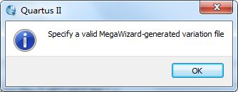
可见其中的注释中还是存放了很多信息的,估计是用来指导Altera的开发工具来编译这个模块的。
这个例子可能不是很合适,因为数据选择开关也许不是所选择的fpga器件中的基本单元。不是很清楚altera的综合工具是如何将lpm_mux单元映射到FPGA内部的基本单元,也许是内部还有一次编译,也许这就是基本单元了。不过不管如何对于用户而言,就不需要写里边的选择器逻辑了,只要直接用就好,altera来保证这个单元实现的正确性和高效性,跟基本单元也就没有多大区别了。
那么,我们的模拟器用什么办法来表示模拟器内的基本单元呢,前面谈过,我们模拟器基于LCOM来做的,因此可以考虑定义基本单元时,用module来定义,然后在module声明前用attribute_instance来说明这是一个HDL4SE模拟器的基本单元,以及实现的LCOM对象的CLSID,使用时将CLSID和实例化参数传输到对象生成例程中,就可以生成一个基本单元的LCOM对象。比如4选1的多路选择器模块,可以这么定义:
(*
  HDL4SE="LCOM",
  CLSID="041F3AA1-97CD-4412-9E8E-D04ADF291AE2",
  softmodule="hdl4se"
*)
module  hdl4se_mux4 #(WIDTH=8)
  (
    input [1:0] sel,
    input [WIDTH-1:0] in0,
    input [WIDTH-1:0] in1,
    input [WIDTH-1:0] in2,
    input [WIDTH-1:0] in3,
    output [WIDTH-1:0] data
  );
   reg [WIDTH-1:0] data;
   wire [1:0] sel;
   wire [WIDTH-1:0] in0, in1, in2, in3;
   always @*
     case (sel)
       2'd0: data = in0;
       2'd1: data = in1;
       2'd2: data = in2;
       2'd3: data = in3;
     endcase
endmodule
画成基本单元图就是:
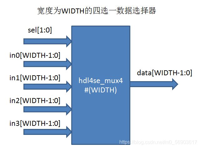 这种定义给出了模拟器中多路选择器的verilog描述,其中的参数WIDTH来定义选择器的数据线宽度。声明前面的attribute_instance中指定HDL4SE=“LCOM"表示这是一个LCOM对象,其CLSID是"041F3AA1-97CD-4412-9E8E-D04ADF291AE2”,softmodule="hdl4se"则表示这个对象实现在hdl4se库中,这个库如果在linux系统中可以用.so文件实现,如果在windows系统中,可以用.dll文件实现。当然也可以编译为静态库,直接连接在模拟器中内置实现,这样就可以不指定softmodule了。
这种定义方式也可以给出实现逻辑供其他的FPGA和ASIC开发平台来使用。对我们的HDL4SE开发平台,已经不需要用户实现了,其中的逻辑,实现在LCOM对象中。编译器发现module定义时指定了HDL4SE="LCOM"和CLSID这样的attribute_instance,就知道这个是基本单元,由软件库(softmodule指定,如果不指定,则有模拟器内置)实现,此时编译器其中的实现逻辑就不再处理。编译成目标代码时直接生成加载对应的库,并根据实例化参数生成LCOM对象。
这种做法给我们很大的想像空间,这样我们可以在体系架构设计之初用c语言或者其他语言,实现很多颗粒度很大的模块作为基本单元,这样可以大大减少体系架构设计之初就要求做很细的RTL实现带来的困难,另外颗粒度大的基本单元可以大幅度减少模拟所需要的时间,可以大幅度提高设计迭代的效率。具体应用中可以把模拟器作为系统的CModel使用,其中的很多模块甚至可以由第三方实现和发布,这种发布可以用二进制库的方式,可以有效保护第三方的知识产权。体系架构设计完成后,再根据具体的目标FPGA平台或ASIC平台进行详细设计和实现。
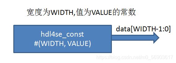
同样,常数基本单元,我们这么定义:
(*
   HDL4SE="LCOM",
   CLSID="8FBE5B87-B484-4f95-8291-DBEF86A1C354",
   softmodule="hdl4se"
*)
module hdl4se_const #(WIDTH=8, VALUE=8'b0)
  (output [WIDTH-1:0] data);
  wire [WIDTH-1:0] data;
  assign data = VALUE;
endmodule
我们不希望你写的verilog源代码中的线网像下面这个样子,让人看不清连接关系:
至少应该是这个样子:

(两张图片都来自于网络)
为此,我们再增加几个线网的合并和拆分基本单元,类似于机房的线缆捆扎器:
(*
   HDL4SE="LCOM",
   CLSID="D5152459-6798-49C8-8376-21EBE8A9EE3C",
   softmodule="hdl4se"
*)
module hdl4se_split4
	#(INPUTWIDTH=32,
         OUTPUTWIDTH0=8, OUTPUTFROM0=0,
         OUTPUTWIDTH1=8, OUTPUTFROM1=8
         OUTPUTWIDTH2=8, OUTPUTFROM2=16,
         OUTPUTWIDTH3=8, OUTPUTFROM3=24
         )
  (
      input [INPUTWIDTH-1:0] wirein
      output [OUTPUTWIDTH0-1:0] wireout0,
      output [OUTPUTWIDTH1-1:0] wireout1,
      output [OUTPUTWIDTH2-1:0] wireout2,
      output [OUTPUTWIDTH3-1:0] wireout3,
    );
  wire [INPUTWIDTH-1:0] wirein;
  wire [OUTPUTWIDTH0-1:0] wireout0;
  wire [OUTPUTWIDTH1-1:0] wireout1;
  wire [OUTPUTWIDTH2-1:0] wireout2;
  wire [OUTPUTWIDTH3-1:0] wireout3;
  assign wireout0 = wirein[OUTPUTWIDTH0+OUTPUTFROM0-1:OUTPUTFROM0];
  assign wireout1 = wirein[OUTPUTWIDTH1+OUTPUTFROM1-1:OUTPUTFROM1];
  assign wireout2 = wirein[OUTPUTWIDTH2+OUTPUTFROM2-1:OUTPUTFROM2];
  assign wireout3 = wirein[OUTPUTWIDTH3+OUTPUTFROM3-1:OUTPUTFROM3];
endmodule

(*
   HDL4SE="LCOM",
   CLSID="0234ECE7-A9C5-406B-9AE7-4841EA0DF7C9",
   softmodule="hdl4se"
*)
module hdl4se_bind4
	#(
         WIDTH0=8,
         WIDTH1=8,
         WIDTH2=8,
         WIDTH3=8
         )
  (
      input [WIDTH0-1:0] wirein0,
      input [WIDTH1-1:0] wirein1,
      input [WIDTH2-1:0] wirein2,
      input [WIDTH3-1:0] wirein3,
      output [WIDTH0+WIDTH1+WIDTH2+WIDTH3-1:0] wireout
    );
  wire [WIDTH0-1:0] wirein0;
  wire [WIDTH1-1:0] wirein1;
  wire [WIDTH2-1:0] wirein2;
  wire [WIDTH3-1:0] wirein3;
  wire [WIDTH0+WIDTH1+WIDTH2+WIDTH3-1:0] wireout;
  assign wireout = {wirein3, wirein2, wirein1, wirein0};
endmodule
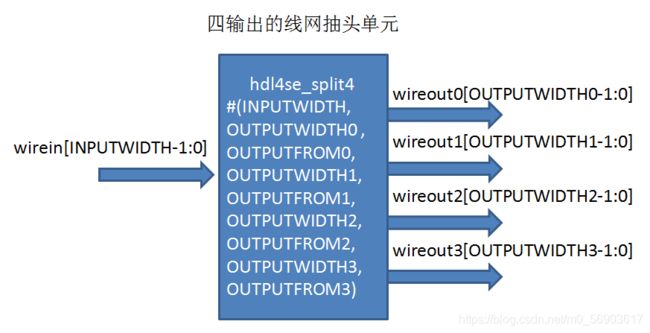
 当然,数字工程师可能从来没有用过这样的模型,因为在FPGA和ASIC设计过程中,这种模型是没有必要存在的,一方面设计过程中直接写线网的部分访问([])或者线网合并运算符号({})即可,不需要这样的描述。另一方面FPGA和ASIC的开发工具认为线网和寄存器本质上都是一位一位的,因此在编译过程中所有的组合电路的输出分拆到位的,每一位一个函数生成的,因此也没有这样的基本单元。然而在hdl4se系统中还是有这个必要的,主要是hdl4se要支持大颗粒度的模拟,这样把线网也尽可能做成大颗粒度的,可以提高模拟效率,多股的线缆是有必要作为基本单元出现的,当然线缆抽头和捆扎也就有必要了。
这样前面的译码器,我们可以用hdl4se的基本单元描述出来:
module dec2seg(input [3:0] dec, output [7:0] seg);
  wire [7:0] wire_cst0;
  hdl4se_const #(8, 8'b00111111) const_cst0(wire_cst0);
  wire [7:0] wire_cst1;
  hdl4se_const #(8, 8'b00000110) const_cst1(wire_cst1);
  wire [7:0] wire_cst2;
  hdl4se_const #(8, 8'b01011011) const_cst2(wire_cst2);
  wire [7:0] wire_cst3;
  hdl4se_const #(8, 8'b01001111) const_cst3(wire_cst3);
  wire [7:0] wire_cst4;
  hdl4se_const #(8, 8'b01100110) const_cst4(wire_cst4);
  wire [7:0] wire_cst5;
  hdl4se_const #(8, 8'b01101101) const_cst5(wire_cst5);
  wire [7:0] wire_cst6;
  hdl4se_const #(8, 8'b01111101) const_cst6(wire_cst6);
  wire [7:0] wire_cst7;
  hdl4se_const #(8, 8'b00000111) const_cst7(wire_cst7);
  wire [7:0] wire_cst8;
  hdl4se_const #(8, 8'b01111111) const_cst8(wire_cst8);
  wire [7:0] wire_cst9;
  hdl4se_const #(8, 8'b01101111) const_cst9(wire_cst9);
  wire [7:0] wire_cst10;
  hdl4se_const #(8, 8'b01111001) const_cst10(wire_cst10);

  hdl4se_mux16 #(8) mux_dec(dec,
    wire_cst0,
    wire_cst1,
    wire_cst2,
    wire_cst3,
    wire_cst4,
    wire_cst5,
    wire_cst6,
    wire_cst7,
    wire_cst8,
    wire_cst9,
    wire_cst10,
    wire_cst10,
    wire_cst10,
    wire_cst10,
    wire_cst10,
    wire_cst10,
    wire_cst10
    seg);
endmodule
画成图就是这样:
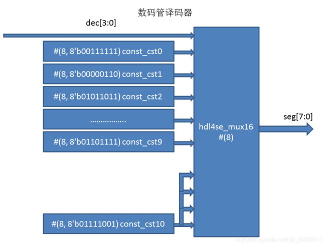 这样的实现都是用hdl4se的基本单元,可以看做是hdl4se下面的门级网表表示方法,即只出现基本单元定义好的module实例和线网定义,也就是对应到写c语言中的汇编语言了,这可以作为我们编译器的中间结果。其实早期的ASIC开发平台中,ASIC中电路就是用画出来的,其中的节点就是工艺库的基本单元,基本单元之间连上线网,每一张图对应一个module,module之间通过输入输出端口连接,形成的图形就是网表。对应到软件设计,早期的ASIC设计其实是在目标平台的汇编语言上进行编程。
我们来罗列一下可能需要的hdl4se的基本单元表:
| 模块名 | 功能 |
|---|---|
| hdl4se_mux2 | 二选一数据选择器 |
| hdl4se_mux4 | 四选一数据选择器 |
| hdl4se_mux8 | 八选一数据选择器 |
| hdl4se_mux16 | 十六选一数据选择器 |
| hdl4se_bind2 | 将两根线网捆扎成一根 |
| hdl4se_bind3 | 将三根线网捆扎成一根 |
| hdl4se_bind4 | 将四根线网捆扎成一根 |
| hdl4se_split2 | 从一根多芯电缆引出两根 |
| hdl4se_split4 | 从一根多芯电缆引出四根 |
| hdl4se_const | 常数 |
| hdl4se_binop | 二元运算符,可以由实例化参数指定宽度和运算 |
| hdl4se_unop | 一元运算符,可以由实例化参数指定宽度和运算符 |
| hdl4se_reg | 寄存器 |
这些基本单元的verilog描述放在一个verilog源代码文件中,使用的时候用include编译指示包括在代码中,即可直接用这种类似于c语言中的嵌入式汇编语言的方式。用户自定义的基本单元也可以这么描述,然后在verilog中可以直接引用。我们把前面定义过的也收集在一起:
/* hdl4se_cell.v */
(*
  HDL4SE="LCOM",
  CLSID="9B0B3D25-346D-48B9-ABB9-ED755910425D",
  softmodule="hdl4se"
*)
module hdl4se_mux2
  #(parameter WIDTH=8)
  (
    input  sel,
    input [WIDTH-1:0] in0,
    input [WIDTH-1:0] in1,
    output [WIDTH-1:0] data
  );
   reg [WIDTH-1:0] data;
   wire sel;
   wire [WIDTH-1:0] in0, in1;
   always @*
     case (sel)
       1'b0: data = in0;
       1'b1: data = in1;
     endcase
endmodule

(*
  HDL4SE="LCOM",
  CLSID="041F3AA1-97CD-4412-9E8E-D04ADF291AE2",
  softmodule="hdl4se"
*)
module hdl4se_mux4
   #(parameter WIDTH=8)
  (
    input [1:0] sel,
    input [WIDTH-1:0] in0,
    input [WIDTH-1:0] in1,
    input [WIDTH-1:0] in2,
    input [WIDTH-1:0] in3,
    output [WIDTH-1:0] data
  );
   reg [WIDTH-1:0] data;
   wire [1:0] sel;
   wire [WIDTH-1:0] in0, in1, in2, in3;
   always @*
     case (sel)
       2'd0: data = in0;
       2'd1: data = in1;
       2'd2: data = in2;
       2'd3: data = in3;
     endcase
endmodule

(*
  HDL4SE="LCOM",
  CLSID="DD99B7F6-9ED1-45BB-8150-ED78EEF982CA",
  softmodule="hdl4se"
*)
module hdl4se_mux8
#(parameter WIDTH=8)
  (
    input [2:0] sel,
    input [WIDTH-1:0] in0,
    input [WIDTH-1:0] in1,
    input [WIDTH-1:0] in2,
    input [WIDTH-1:0] in3,
    input [WIDTH-1:0] in4,
    input [WIDTH-1:0] in5,
    input [WIDTH-1:0] in6,
    input [WIDTH-1:0] in7,
    output [WIDTH-1:0] data
  );
   reg [WIDTH-1:0] data;
   wire [2:0] sel;
   wire [WIDTH-1:0] in0, in1, in2, in3, in4, in5, in6, in7;
   always @*
     case (sel)
       3'd0: data = in0;
       3'd1: data = in1;
       3'd2: data = in2;
       3'd3: data = in3;
       3'd4: data = in4;
       3'd5: data = in5;
       3'd6: data = in6;
       3'd7: data = in7;
     endcase
endmodule

(*
  HDL4SE="LCOM",
  CLSID="69B4A095-0644-4B9E-9CF0-295474D7C243",
  softmodule="hdl4se"
*)
module hdl4se_mux16
    #(parameter WIDTH=8)
  (
    input [3:0] sel,
    input [WIDTH-1:0] in0,
    input [WIDTH-1:0] in1,
    input [WIDTH-1:0] in2,
    input [WIDTH-1:0] in3,
    input [WIDTH-1:0] in4,
    input [WIDTH-1:0] in5,
    input [WIDTH-1:0] in6,
    input [WIDTH-1:0] in7,
    input [WIDTH-1:0] in8,
    input [WIDTH-1:0] in9,
    input [WIDTH-1:0] in10,
    input [WIDTH-1:0] in11,
    input [WIDTH-1:0] in12,
    input [WIDTH-1:0] in13,
    input [WIDTH-1:0] in14,
    input [WIDTH-1:0] in15,
    output [WIDTH-1:0] data
  );
   reg [WIDTH-1:0] data;
   wire [3:0] sel;
   wire [WIDTH-1:0] in0, in1, in2, in3, in4, in5, in6, in7,
                    in8, in9, in10, in11, in12, in13, in14, in15;
   always @*
     case (sel)
       4'd0: data = in0;
       4'd1: data = in1;
       4'd2: data = in2;
       4'd3: data = in3;
       4'd4: data = in4;
       4'd5: data = in5;
       4'd6: data = in6;
       4'd7: data = in7;
       4'd8: data = in8;
       4'd9: data = in9;
       4'd10: data = in10;
       4'd11: data = in11;
       4'd12: data = in12;
       4'd13: data = in13;
       4'd14: data = in14;
       4'd15: data = in15;
     endcase
endmodule

(*
   HDL4SE="LCOM",
   CLSID="29D9C8D6-810E-41D0-BCEF-A5B86EE1EE01",
   softmodule="hdl4se"
*)
module hdl4se_split2
    #(parameter INPUTWIDTH=16,
      OUTPUTWIDTH0=8, OUTPUTFROM0=0,
      OUTPUTWIDTH1=8, OUTPUTFROM1=8)
    (
      input [INPUTWIDTH-1:0] wirein,
      output [OUTPUTWIDTH0-1:0] wireout0,
      output [OUTPUTWIDTH1-1:0] wireout1
    );
  wire [INPUTWIDTH-1:0] wirein;
  wire [OUTPUTWIDTH0-1:0] wireout0;
  wire [OUTPUTWIDTH1-1:0] wireout1;
  assign wireout0 = wirein[OUTPUTWIDTH0+OUTPUTFROM0-1:OUTPUTFROM0];
  assign wireout1 = wirein[OUTPUTWIDTH1+OUTPUTFROM1-1:OUTPUTFROM1];
endmodule

(*
   HDL4SE="LCOM",
   CLSID="D5152459-6798-49C8-8376-21EBE8A9EE3C",
   softmodule="hdl4se"
*)
module hdl4se_split4
    #(parameter INPUTWIDTH=32,
      OUTPUTWIDTH0=8, OUTPUTFROM0=0,
      OUTPUTWIDTH1=8, OUTPUTFROM1=8,
      OUTPUTWIDTH2=8, OUTPUTFROM2=16,
      OUTPUTWIDTH3=8, OUTPUTFROM3=24
    )
    (
      input [INPUTWIDTH-1:0] wirein,
      output [OUTPUTWIDTH0-1:0] wireout0,
      output [OUTPUTWIDTH1-1:0] wireout1,
      output [OUTPUTWIDTH2-1:0] wireout2,
      output [OUTPUTWIDTH3-1:0] wireout3
    );
  wire [INPUTWIDTH-1:0] wirein;
  wire [OUTPUTWIDTH0-1:0] wireout0;
  wire [OUTPUTWIDTH1-1:0] wireout1;
  wire [OUTPUTWIDTH2-1:0] wireout2;
  wire [OUTPUTWIDTH3-1:0] wireout3;
  assign wireout0 = wirein[OUTPUTWIDTH0+OUTPUTFROM0-1:OUTPUTFROM0];
  assign wireout1 = wirein[OUTPUTWIDTH1+OUTPUTFROM1-1:OUTPUTFROM1];
  assign wireout2 = wirein[OUTPUTWIDTH2+OUTPUTFROM2-1:OUTPUTFROM2];
  assign wireout3 = wirein[OUTPUTWIDTH3+OUTPUTFROM3-1:OUTPUTFROM3];
endmodule

(*
   HDL4SE="LCOM",
   CLSID="DA8C1494-B6F6-4910-BB2B-C9BCFCB9FAD0",
   softmodule="hdl4se"
*)
module hdl4se_bind2
    #(parameter INPUTWIDTH0=8,
      INPUTWIDTH1=8
     )
    (
      input [INPUTWIDTH0-1:0] wirein0,
      input [INPUTWIDTH1-1:0] wirein1,
      output [INPUTWIDTH0+INPUTWIDTH1-1:0] wireout
    );
  wire [INPUTWIDTH0-1:0] wirein0;
  wire [INPUTWIDTH1-1:0] wirein1;
  wire [INPUTWIDTH0+INPUTWIDTH1-1:0] wireout;
  assign wireout = {wirein1, wirein0};
endmodule

(*
   HDL4SE="LCOM",
   CLSID="D1F303E2-3ED1-42FD-8762-3AA623DA901E",
   softmodule="hdl4se"
*)
module hdl4se_bind3
    #(parameter INPUTWIDTH0=8,
      INPUTWIDTH1=8,
      INPUTWIDTH2=8
     )
    (
      input [INPUTWIDTH0-1:0] wirein0,
      input [INPUTWIDTH1-1:0] wirein1,
      input [INPUTWIDTH2-1:0] wirein2,
      output [INPUTWIDTH0+INPUTWIDTH1+INPUTWIDTH2-1:0] wireout
    );
  wire [INPUTWIDTH0-1:0] wirein0;
  wire [INPUTWIDTH1-1:0] wirein1;
  wire [INPUTWIDTH2-1:0] wirein2;
  wire [INPUTWIDTH0+INPUTWIDTH1+INPUTWIDTH2-1:0] wireout;
  assign wireout = {wirein2, wirein1, wirein0};
endmodule

(*
   HDL4SE="LCOM",
   CLSID="0234ECE7-A9C5-406B-9AE7-4841EA0DF7C9",
   softmodule="hdl4se"
*)
module hdl4se_bind4
    #(parameter WIDTH0=8,
      WIDTH1=8,
      WIDTH2=8,
      WIDTH3=8
     )
    (
      input [WIDTH0-1:0] wirein0,
      input [WIDTH1-1:0] wirein1,
      input [WIDTH2-1:0] wirein2,
      input [WIDTH3-1:0] wirein3,
      output [WIDTH0+WIDTH1+WIDTH2+WIDTH3-1:0] wireout
    );
  wire [WIDTH0-1:0] wirein0;
  wire [WIDTH1-1:0] wirein1;
  wire [WIDTH2-1:0] wirein2;
  wire [WIDTH3-1:0] wirein3;
  wire [WIDTH0+WIDTH1+WIDTH2+WIDTH3-1:0] wireout;
  assign wireout = {wirein3, wirein2, wirein1, wirein0};
endmodule

(*
   HDL4SE="LCOM",
   CLSID="8FBE5B87-B484-4f95-8291-DBEF86A1C354",
   softmodule="hdl4se"
*)
module hdl4se_const
    #(parameter WIDTH=8, VALUE=8'b0)
    (output [WIDTH-1:0] data);
    wire [WIDTH-1:0] data;
    assign data = VALUE;
endmodule

`define BINOP_ADD 0
`define BINOP_SUB 1
`define BINOP_MUL 2
`define BINOP_DIV 3
`define BINOP_EQ 4
`define BINOP_NE 5
`define BINOP_LT 6
`define BINOP_LE 7
`define BINOP_GE 8
`define BINOP_GT 9
`define BINOP_AND 10
`define BINOP_OR 11
`define BINOP_XOR 12
(*
   HDL4SE="LCOM",
   CLSID="060FB913-1C0F-4704-8EC2-A08BF5387062",
   softmodule="hdl4se"
*)
module hdl4se_binop
    #(parameter INPUTWIDTH0=8, INPUTWIDTH1=8, OUTPUTWIDTH=8, OP=`BINOP_ADD)
    (
      input [INPUTWIDTH0-1:0] wirein0,
      input [INPUTWIDTH1-1:0] wirein1,
      output [OUTPUTWIDTH-1:0] wireout
    );
  wire [INPUTWIDTH0-1:0] wirein0;
  wire [INPUTWIDTH1-1:0] wirein1;
  wire [OUTPUTWIDTH-1:0] wireout;

endmodule

`define UNOP_NEG 0
`define UNOP_NOT 1
`define UNOP_AND 2
`define UNOP_OR  3
`define UNOP_XOR 4
(*
   HDL4SE="LCOM",
   CLSID="E6772805-57BB-4b39-A10D-FDA6A4810E3B",
   softmodule="hdl4se"
*)
module hdl4se_unop
    #(parameter INPUTWIDTH=8, OUTPUTWIDTH=8, OP=`UNOP_NEG)
    (
      input [INPUTWIDTH-1:0] wirein,
      output [OUTPUTWIDTH-1:0] wireout
    );
  wire [INPUTWIDTH-1:0] wirein;
  wire [OUTPUTWIDTH-1:0] wireout;
endmodule

(*
   HDL4SE="LCOM",
   CLSID="76FBFD4B-FEAD-45fd-AA27-AFC58AC241C2",
   softmodule="hdl4se"
*)
module hdl4se_reg
    #(parameter WIDTH=8)
    (
      input wClk,
      input [WIDTH-1:0] wirein,
      output [WIDTH-1:0] wireout
    );
  wire [WIDTH-1:0] wirein;
  reg [WIDTH-1:0] wireout;
  always @(posedge wClk) wireout <= wirein;
endmodule
有了这个基本库,相当于我们有了hdl4se模拟器的汇编语言,我们就可以把verilog源代码先编译成汇编语言实现(当然源代码中也可以用嵌入式汇编的)。我们先完成例子在讨论编译过程。
4.3 示例程序及编译
我们把先把上一节中实现的主模块,计数器,和本节实现的译码器连接到一起,用verilog完成了前面例子的要求,简单起见,我们可以把它们放在同一个main.v文件中。
/* main.v */
module counter
    #(parameter WIDTH=4, MAXVALUE=9, RESETVALUE=0)
(input wClk, nwReset, wCounterIt,
output [WIDTH-1:0] bCouter,
output wCounterOverflow);

/*WIDTH宽度的寄存器用来保存计数器的值*/
reg [WIDTH-1:0] bCurrentCounter;
/*定义一个寄存器来表示计数器是否溢出*/
reg wOverflow;
wire [WIDTH-1:0] bCounter;
wire wCounterOverflow;
/*输出线网直接连接在寄存器上*/
assign bCounter = bCurrentCounter;
assign wCounterOverflow = wOverflow;
always @(posedge wClk) begin
  if (~nwReset) begin /*复位处理*/
  		bCurrentCounter <= RESETVALUE;
        wOverflow <= 1’b0;
  end else begin
    /*复位信号无效的情况,开始计数操作 */
	if (wCounterIt) begin
		if (bCurrentCounter == MAXVALUE) begin
			bCurrentCounter <= RESETVALUE;
            wOverflow <= 1’b1;
        end else begin
          bCurrentCounter <= bCurrentCounter + 1;
          wOverflow <= 1’b0;
        end
    end /*wCounterIt*/
  end /*nwReset*/
end /*always*/
endmodule

module dec2seg(input [3:0] dec, output [7:0] seg);
wire [3:0] dec;
reg [7:0] seg;
always @(dec)
  case (dec)
    4'd0:seg = 8'b00111111;
    4'd1:seg = 8'b00000110;
    4'd2:seg = 8'b01011011;
    4'd3:seg = 8'b01001111;
    4'd4:seg = 8'b01100110;
    4'd5:seg = 8'b01101101;
    4'd6:seg = 8'b01111101;
    4'd7:seg = 8'b00000111;
    4'd8:seg = 8'b01111111;
    4'd9:seg = 8'b01101111;
    default:seg = 8'b01111001;
  endcase
endmodule

module main(wClk, nwReset,
            wWrite, bWriteAddr, bWiteData, bWriteMask,
            wRead, bReadAddr, bReadData);
input wClk, nwReset;
output wWrite;
output [31:0] bWriteAddr;
output [31:0] bWriteData;
output [3:0]  bWriteMask;
output wRead;
output [31:0] bReadAddr;
input [31:0]  bReadData;

wire [31:0] bReadAddr;
wire [31:0]bReadData;
wire wRead;
wire wButton0Pressed;
wire wButton1Pressed;
wire wButton2Pressed;
/*我们一直在读按键的状态*/
assign wRead = 1’b1;
assign bReadAddr = 32’hF000_0000;
assign wButton0Pressed = bReadData[0];
assign wButton1Pressed = bReadData[1];
assign wButton2Pressed = bReadData[2];

/* 以下是计数器连接 */
assign wCounterin0 = wCounterIt;
wire wCountin0, wCountin1, wCountin2,
     wCountin3, wCountin4, wCountin5,
     wCountin6, wCountin7, wCountin8,
     wCountin9;
wire [3:0] bCount0, bCount1, bCount2, bCount3, bCount4,
           bCount5, bCount6, bCount7, bCount8, bCount9;
counter #(4,9,0) counter0(wClk, nwCounterReset, wCounterin0, bCount0, wCounterin1);
counter #(4,9,0) counter1(wClk, nwCounterReset, wCounterin1, bCount1, wCounterin2);
counter #(4,9,0) counter2(wClk, nwCounterReset, wCounterin2, bCount2, wCounterin3);
counter #(4,9,0) counter3(wClk, nwCounterReset, wCounterin3, bCount3, wCounterin4);
counter #(4,9,0) counter4(wClk, nwCounterReset, wCounterin4, bCount4, wCounterin5);
counter #(4,9,0) counter5(wClk, nwCounterReset, wCounterin5, bCount5, wCounterin6);
counter #(4,9,0) counter6(wClk, nwCounterReset, wCounterin6, bCount6, wCounterin7);
counter #(4,9,0) counter7(wClk, nwCounterReset, wCounterin7, bCount7, wCounterin8);
counter counter8(wClk, nwCounterReset, wCounterin8, bCounter8, wCounterin9);
counter #(RESETVALUE=0, WIDTH=4) count9(.wClk(wClk), .nwReset(nwCounterReset),
.wCounteit(wCounterin9), .bCounter(bCount9),
.wConteroverflow());

reg wCounterIt;
/*
下面的寄存器来指示是否复位计数器值,
它是一个低电平有效的信号
*/
reg nwResetCount;

always @* begin
  if (~nwReset) begin
nwResetCount = 1’b0;
  end else begin
if (wButton0Pressed)
  nwResetCount = 1’b0;
else
  nwResetCount = 1’b1;
  end
end

/*下面的代码来生成wCounterIt */
always @(posedge wClk) begin
/* 计数器一开始是不动作的,在外
部按第0个键时对计数器的值进行清
零,按第1个键时停止计数,按第2
个键开始计数,开始计数时计数值
从当前值开始(如果多个键同时按
下,则以序号小的为准)
*/
  if (~nwReset) begin
    wCounterIt <= 1’b0;
  end else if (wButton0Pressed==1’b0) begin
    if (wButton1Pressed) begin
      wCounterIt <= 1’b0;
    end else if (wButton2Pressed) begin
      wCounterIt <= 1’b1;
    end
  end
end

/* 以下是译码器连接,十个计数器的输出对应到十个译码器 */
wire code0[7:0];
wire code1[7:0];
wire code2[7:0];
wire code3[7:0];
wire code4[7:0];
wire code5[7:0];
wire code6[7:0];
wire code7[7:0];
wire code8[7:0];
wire code9[7:0];
dec2seg dec0(bCount0, code0);
dec2seg dec1(bCount1, code1);
dec2seg dec2(bCount2, code2);
dec2seg dec3(bCount3, code3);
dec2seg dec4(bCount4, code4);
dec2seg dec5(bCount5, code5);
dec2seg dec6(bCount6, code6);
dec2seg dec7(bCount7, code7);
dec2seg dec8(bCount8, code8);
dec2seg dec9(bCount9, code9);
/*下面将译码器输出写到外面去,控制数码管显示*/
/*
我们用寄存器输出,
注意到我们一次只能输出4个字节,因此一个
时钟周期最多只能控制四个数码管,我们分三段
来写,优先写变化慢的,用对应计数器的输入
标志来得到是否变化。不过要注意计数器的输出
晚一拍出来,所以变化情况也寄存一拍。
*/
reg [2:0] bCounterChanged;
always @(posedge wClk)
if (~nwReset)
  bCounterChanged<= 3'b0;
else
  bCounterChanged <= {
  	wCounterin9 | wCounterin8,
  	wCounterin7 | wCounterin6 |	wCounterin5 | wCounterin4,
  	wCounterin3 | wCounterin2 |	wCounterin1 | wCounterin0
  };

reg wWrite;
reg [31:0] bWriteAddr;
reg [31:0] bWriteData;
reg [3:0] bWriteMask;
always @posedge wClk)
if (~nwReset) begin
  wWrite <= 1'b0;
  bWriteAddr <= 32'b0;
  bWriteData <= 32'b0;
  bWriteMask <= 4'b0;
end else begin
 wWrite <= 1'b0;
 bWriteMask <= 4'b0;
 if (bCounterChanged[2]) begin
   wWrite <= 1'b1;
   bWriteMask <= 4'b1100;
   bWriteAddr <= 32'hf0000018;
   bWriteData <= {16'b0, code9, code8};
 end else if (bCounterChanged[1]) begin
   wWrite <= 1'b1;
   bWriteAddr <= 32'hf0000014;
   bWriteData <= {code7, code6, code5, code4};
 end  else if (bCounterChanged[0]) begin
   wWrite <= 1'b1;
   bWriteAddr <= 32'hf0000010;
   bWriteData <= {code3, code2, code1, code0};
 end
end
endmodule
我们目前没有编译器和模拟器,我现在也不知这个实现是否正确,感觉就像火星着陆器进入了黑障时间似的。先只好手工把它们转换成成所谓的用hdl4se模拟器下的门级代码(汇编语言)。
c语言下面,编译时对函数有两种处理方法,一种是每个函数单独编译,然后生成函数调用指令来完成函数函数调用,还有一种方法是干脆不生成函数调用指令,遇上函数调用就把它当成是inline类型的,也就是把函数的代码复制一份在函数调用处,取代函数调用指令,当然复制代码时要处理参数传递和返回值对接。
FPGA和ASIC开发工具一般都是把模块都展开,最后只有一个用基本单元做的moudule,所以一般看FPGA编译后的网表(netlist)文件都很大,中间只有一个module定义,就是主模块(顶层模块)。
hdl4se下我们选择每个模块独立编译,最终的目标码中保留module这个概念,通过module的互联来完成实例化。
前面已经给出的译码器的编译结果(hdl4se汇编语言:全部用hdl4se基本单元和线网搭建的电路)。可以用汇编器(目前当然也只能是手工的了),转成目标代码。我们的目标代码可以是c语言源代码(早期编程序有见过直接修改目标代码文件的),下面的函数是用来生成基本单元的:
/* 生成基本单元,并把基本单元加到父节点中,父节点是一个Module */
IHDL4SEUnit ** hdl4seCreateUnit(IHDL4SEModule ** parent, IID_TYPE clsid, char * instanceparam, char * name)
{
  PARAMITEM param[3];
  IHDL4SEUnit ** result = NULL;
  param[0].name=PARAMID_HDL4SE_UNIT_INSTANCE_PARAMETERS;
  param[0].pValue = instanceparam;
  param[1].name = PARAMID_HDL4SE_UNIT_NAME;
  param[1].pValue = name;
  param[2].name = PARAMID_HDL4SE_UNIT_PARENT;
  param[2].pValue = parent;
  objectCreateEx(CLSID_HDL4SE_WIRE, param, 3, IID_IHDL4SEUNIT, &result);
  objectCall1(parent, AddUnit, result);
  return result;
}
有了这个函数的支持,我们给出译码器的目标代码(在HDL4SE中,verilog的.v文件是源代码,翻译的基本单元表达方式是汇编语言,目标代码这里是用c实现的):
static IHDL4SEUnit** hdl4seCreateDec2seg(IHDL4SEModule** parent, char* instanceparam, char* name) { /* module dec2seg */
	IHDL4SEUnit** wire_const[11];
	IHDL4SEUnit** unit_const[11];
	IHDL4SEUnit** unit_mux16 = NULL;
	IHDL4SEModule** module_dec2seg = NULL;
	IHDL4SEUnit** unit_dec2seg = NULL;
	int i;
	char temp[128];
	char* constparam[11] = {
		"8, 8'b00111111",
		"8, 8'b00000110",
		"8, 8'b01011011",
		"8, 8'b01001111",
		"8, 8'b01100110",
		"8, 8'b01101101",
		"8, 8'b01111101",
		"8, 8'b00000111",
		"8, 8'b01111111",
		"8, 8'b01101111",
		"8, 8'b01111001"
	};

	/* 生成模块对象 */
	unit_dec2seg = hdl4seCreateUnit(parent, CLSID_HDL4SE_MODULE, instanceparam, name);
	/* 得到对象的IHDL4SEModule 接口 */
	objectQueryInterface(unit_dec2seg, IID_HDL4SEMODULE, (void **)&module_dec2seg);
	/* 增加端口 */
	objectCall3(module_dec2seg, AddPort, 4, PORTTYPE_INPUT,  "0.dec");
	objectCall3(module_dec2seg, AddPort, 8, PORTTYPE_OUTPUT, "1.seg");

	for (i = 0; i < 11; i++) {
		char tempname[32];
		sprintf(tempname, "wire_cst%d", i);
		wire_const[i] = hdl4seCreateUnit(module_dec2seg, CLSID_HDL4SE_WIRE, "8", tempname);
		sprintf(tempname, "const_cst%d", i);
		unit_const[i] = hdl4seCreateUnit(module_dec2seg, CLSID_HDL4SE_CONST, constparam[i], tempname);
		objectCall3(wire_const[i], Connect, 0, unit_const[i], 0);
	}
	/* 生成数据选择器unit_mux */
	unit_mux16 = hdl4seCreateUnit(module_dec2seg, CLSID_HDL4SE_MUX16, "8", "mux_dec");
	/*mux的输入连接到输入端口dec和线网constall上*/
	objectCall3(unit_mux16, Connect, 0, unit_dec2seg, 0);
	for (i = 0; i < 10; i++) {
		objectCall3(unit_mux16, Connect, i+1, wire_const[i], 0);
	}
	for (; i < 16; i++) {
		objectCall3(unit_mux16, Connect, i+1, wire_const[10], 0);
	}
	/* 译码模块的输出seg连接到数据先择器的输出*/
	objectCall3(unit_dec2seg, Connect, 1, unit_mux16, 17);

	/*释放module接口*/
	objectRelease(module_dec2seg);
	/*返回unit接口*/
	return unit_dec2seg;
}
嗯,目标代码比汇编语言长多了啊,手工才能生成用数组和for循环的目标代码。
同样给出计数器的汇编代码,注意,这是一个带实例参数的模块定义:
module counter
    #(parameter WIDTH=4, MAXVALUE=9, RESETVALUE=0)
(input wClk, nwReset, wCounterIt,
output [WIDTH-1:0] bCouter,
output wCounterOverflow);

/*WIDTH宽度的寄存器用来保存计数器的值*/
  wire [WIDTH-1:0] wirein_bCurrentCounter,
                   wireout_bCurrentCounter;
  hdl4se_reg #(WIDTH) bCurrentCounter(
      wClk,
      wirein_bCurrentCounter,
      wireout_bCurrentCounter
    );
/*定义一个寄存器来表示计数器是否溢出*/
  wire wirein_wOverflow, wireout_wOverflow;
  hdl4se_reg #(1, 0) reg_wOverflow(
      wClk,
      wirein_wOverflow,
      wireout_wOverflow
    );
wire [WIDTH-1:0] bCounter;
wire wCounterOverflow;
assign bCounter = wireout_bCurrentCounter;
assign wCounterOverflow = wireout_wOverflow;

wire [WIDTH-1:0] bConst_MAXVALUE;
/*常数 MAXVALUE*/
hdl4se_const #(WIDTH, MAXVALUE) const_MAXVALUE(bConst_MAXVALUE);
/*常数 RESETVALUE*/
wire [WIDTH-1:0] bConst_RESETVALUE;
hdl4se_const #(WIDTH, RESETVALUE) const_RESETVALUE(bConst_RESETVALUE);

wire wEQ_bCurrentCounter_MAXVALUE;
/* 比较器 bCurrentCounter == MAXVALUE */
hdl4se_binop #(WIDTH, WIDTH, 1, BINOP_EQ)
   binop_EQ_bCurrentCounter_MAXVALUE(
      wireout_bCurrentCounter,
      bConst_MAXVALUE,
      wEQ_bCurrentCounter_MAXVALUE
    );

/* bCurrentCounter+1 用加法器实现 */
/*常数 1*/
wire [WIDTH-1:0] bConst_One;
wire [WIDTH-1:0] bCurrentCounterPlusOne;
hdl4se_const #(WIDTH, 1) const_One(bConst_One);
hdl4se_binop #(WIDTH, WIDTH, 1, BINOP_ADD)
   binop_bCurrentCounterInc(
      wireout_bCurrentCounter,
      bConst_One,
      bCurrentCounterPlusOne
    );

wire [WIDTH-1:0] bCurrentCounter_if_wCounterIt;
hdl4se_mux2 #(WIDTH) mux_bCurrentCounter_if_wCounterIt
    ( wEQ_bCurrentCounter_MAXVALUE,
      bCurrentCounterPlusOne,
      bConst_RESETVALUE,
      bCurrentCounter_if_wCounterIt);

wire wConst_1;
hdl4se_const #(1, 1) const_1(wConst_1);
wire wConst_0;
hdl4se_const #(1, 0) const_0(wConst_0);

wire wOverflow_if_wCounterIt;
hdl4se_mux2 #(1) mux_wOverflow_if_wCounterIt
    ( wEQ_bCurrentCounter_MAXVALUE,
      wConst_0,
      wConst_1,
      wOverflow_if_wCounterIt);

wire [WIDTH-1:0] bCurrentCounter_if_nwReset;
hdl4se_mux2 #(WIDTH) mux_bCurrentCounter_if_nwReset
    ( wCounterIt,
      wireout_bCurrentCounter,
      bCurrentCounter_if_wCounterIt,
      bCurrentCounter_if_nwReset);

wire wOverflow_if_nwReset;
hdl4se_mux2 #(1) mux_wOverflow_if_nwReset
    ( wCounterIt,
      wireout_wOverflow,
      wOverflow_if_wCounterIt,
      wOverflow_if_nwReset);

hdl4se_mux2 #(WIDTH) mux_bCurrentCounter
    ( nwReset,
      bConst_RESETVALUE,
      bCurrentCounter_if_nwReset,
      wirein_bCurrentCounter);

hdl4se_mux2 #(1) mux_wOverflow
    ( wCounterIt,
      const_0,
      wOverflow_if_nwReset,
      wirein_wOverflow);

endmodule
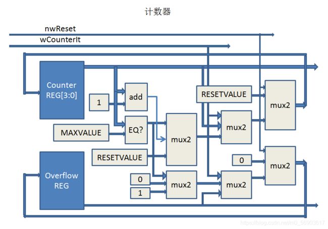
画出图是这样的,蓝色块是寄存器,灰色块是组合电路:
调用人形汇编器,得到计数器模块的目标代码:
static IHDL4SEUnit** hdl4seCreateCounter(IHDL4SEModule** parent, char* instanceparam, char* name) { /* module counter */
	IHDL4SEModule** module_counter = NULL;
	IHDL4SEUnit** unit_counter = NULL;
	int width, maxvalue, resetvalue;
	char temp[128];
	sscanf(instanceparam, "%d, %d, %d", &width, &maxvalue, &resetvalue);
	/* 生成模块对象 */
	unit_counter = hdl4seCreateUnit(parent, CLSID_HDL4SE_MODULE, instanceparam, name);
	/* 得到对象的IHDL4SEModule 接口 */
	objectQueryInterface(unit_counter, IID_HDL4SEMODULE, (void **)&module_counter);
	/* 增加端口 */
	objectCall3(module_counter, AddPort, 1, PORTTYPE_INPUT, "0.nwReset");
	objectCall3(module_counter, AddPort, 1, PORTTYPE_INPUT, "1.wCounterIt");
	objectCall3(module_counter, AddPort, width, PORTTYPE_OUTPUT, "2.bCouter");
	objectCall3(module_counter, AddPort, 1, PORTTYPE_OUTPUT, "3.wCounterOverflow");

	/*WIDTH宽度的寄存器用来保存计数器的值*/
	sprintf(temp, "%d", width);
	IHDL4SEUnit** reg_bCurrentCounter = hdl4seCreateUnit(module_counter, CLSID_HDL4SE_REG, temp, "bCurrentCounter");

	/*定义一个寄存器来表示计数器是否溢出*/
	IHDL4SEUnit** reg_wOverflow = hdl4seCreateUnit(module_counter, CLSID_HDL4SE_REG, "1", "wOverflow");

	objectCall3(unit_counter, Connect, 2, reg_bCurrentCounter, 1);
	objectCall3(unit_counter, Connect, 3, reg_wOverflow, 1);


	sprintf(temp, "%d, %d", width, maxvalue);
	IHDL4SEUnit** unit_const_MAXVALUE = hdl4seCreateUnit(module_counter, CLSID_HDL4SE_CONST, temp, "const_MAXVALUE");

	sprintf(temp, "%d, %d", width, resetvalue);
	IHDL4SEUnit** unit_const_RESETVALUE = hdl4seCreateUnit(module_counter, CLSID_HDL4SE_CONST, temp, "const_RESETVALUE");

	sprintf(temp, "%d, %d, 1, %d", width, width, BINOP_EQ);
	IHDL4SEUnit** unit_binop_EQ_bCurrentCounter_MAXVALUE = hdl4seCreateUnit(module_counter, CLSID_HDL4SE_BINOP, temp, "binop_EQ_bCurrentCounter_MAXVALUE");
	objectCall3(unit_binop_EQ_bCurrentCounter_MAXVALUE, Connect, 0, reg_bCurrentCounter, 1);
	objectCall3(unit_binop_EQ_bCurrentCounter_MAXVALUE, Connect, 1, unit_const_MAXVALUE, 0);

	/* bCurrentCounter+1 用加法器实现 */
	  /* 常数 1 */
	sprintf(temp, "%d, %d", width, 1);
	IHDL4SEUnit** unit_const_One = hdl4seCreateUnit(module_counter, CLSID_HDL4SE_CONST, temp, "const_One");

	/* bCurrentCounter + 1 */
	sprintf(temp, "%d, %d, %d, %d", width, width, width, BINOP_ADD);
	IHDL4SEUnit** unit_binop_bCurrentCounterPlusOne = hdl4seCreateUnit(module_counter, CLSID_HDL4SE_BINOP, temp, "binop_bCurrentCounterInc");
	objectCall3(unit_binop_bCurrentCounterPlusOne, Connect, 0, reg_bCurrentCounter, 1);
	objectCall3(unit_binop_bCurrentCounterPlusOne, Connect, 1, unit_const_One, 0);

	/* if语句用数据选择器实现 */
	sprintf(temp, "%d", width);
	IHDL4SEUnit** unit_mux_bCounter_If_EQMAXvalue = hdl4seCreateUnit(module_counter, CLSID_HDL4SE_MUX2, temp, "mux_bCurrentCounter_if_wCounterIt");
	objectCall3(unit_mux_bCounter_If_EQMAXvalue, Connect, 0, unit_binop_EQ_bCurrentCounter_MAXVALUE, 2);
	objectCall3(unit_mux_bCounter_If_EQMAXvalue, Connect, 1, unit_binop_bCurrentCounterPlusOne, 2);
	objectCall3(unit_mux_bCounter_If_EQMAXvalue, Connect, 2, unit_const_RESETVALUE, 0);

	IHDL4SEUnit** unit_const_0 = hdl4seCreateUnit(module_counter, CLSID_HDL4SE_CONST, "1, 0", "const_0");
	IHDL4SEUnit** unit_const_1 = hdl4seCreateUnit(module_counter, CLSID_HDL4SE_CONST, "1, 1", "const_1");

	IHDL4SEUnit** unit_mux_wOverflow_If_EQMAXvalue = hdl4seCreateUnit(module_counter, CLSID_HDL4SE_MUX2, "1", "mux_wOverflow_if_wCounterIt");
	objectCall3(unit_mux_wOverflow_If_EQMAXvalue, Connect, 0, unit_binop_EQ_bCurrentCounter_MAXVALUE, 2);
	objectCall3(unit_mux_wOverflow_If_EQMAXvalue, Connect, 1, unit_const_0, 0);
	objectCall3(unit_mux_wOverflow_If_EQMAXvalue, Connect, 2, unit_const_1, 0);

	sprintf(temp, "%d", width);
	IHDL4SEUnit** unit_mux_bCurrentCounter_if_nwReset = hdl4seCreateUnit(module_counter, CLSID_HDL4SE_MUX2, temp, "mux_bCurrentCounter_if_nwReset");
	objectCall3(unit_mux_bCurrentCounter_if_nwReset, Connect, 0, module_counter, 1);
	objectCall3(unit_mux_bCurrentCounter_if_nwReset, Connect, 1, reg_bCurrentCounter, 0);
	objectCall3(unit_mux_bCurrentCounter_if_nwReset, Connect, 2, unit_mux_bCounter_If_EQMAXvalue, 2);

	IHDL4SEUnit** unit_mux_wOverflow_if_nwReset = hdl4seCreateUnit(module_counter, CLSID_HDL4SE_MUX2, "1", "mux_wOverflow_if_nwReset");
	objectCall3(unit_mux_wOverflow_if_nwReset, Connect, 0, module_counter, 1);
	objectCall3(unit_mux_wOverflow_if_nwReset, Connect, 1, unit_const_0, 0);
	objectCall3(unit_mux_wOverflow_if_nwReset, Connect, 2, unit_mux_wOverflow_If_EQMAXvalue, 2);

	IHDL4SEUnit** unit_mux_bCurrentCounter = hdl4seCreateUnit(module_counter, CLSID_HDL4SE_MUX2, temp, "mux_bCurrentCounter");
	objectCall3(unit_mux_bCurrentCounter, Connect, 0, module_counter, 0);
	objectCall3(unit_mux_bCurrentCounter, Connect, 1, unit_const_RESETVALUE, 0);
	objectCall3(unit_mux_bCurrentCounter, Connect, 2, unit_mux_bCurrentCounter_if_nwReset, 2);
	objectCall3(reg_bCurrentCounter, Connect, 0, unit_mux_bCurrentCounter, 3);

	IHDL4SEUnit** unit_mux_wOverflow = hdl4seCreateUnit(module_counter, CLSID_HDL4SE_MUX2, "1", "mux_wOverflow");
	objectCall3(unit_mux_wOverflow, Connect, 0, module_counter, 0);
	objectCall3(unit_mux_wOverflow, Connect, 1, unit_const_0, 0);
	objectCall3(unit_mux_wOverflow, Connect, 2, unit_mux_wOverflow_if_nwReset, 2);
	objectCall3(reg_wOverflow, Connect, 0, unit_mux_wOverflow, 3);

	/*释放module接口*/
	objectRelease(module_counter);
	/*返回unit接口*/
	return unit_counter;

}
其中做了一些优化工作,简化了线网连接方面的冗余。其实两个模块的端口之间如果只有一根电缆连接,这根电缆又只用来连接这两个模块,此时可以将两个模块直接连接在一起,不用中间通过线网转接了,这样运行时应该能快点。
主模块的汇编代码:
module main(input wClk,
            input nwReset,
            output wWrite,
            output [31:0] bWriteAddr,
            output [31:0] bWiteData,
            output [3:0] bWriteMask,
            output wRead,
            output [31:0] bReadAddr,
            input [31:0] bReadData);

  wire wButton0Pressed;
  wire wButton1Pressed;
  wire wButton2Pressed;
  /*我们一直在读按键的状态*/
  hdl4se_const #(1, 1) const_0_wRead(wRead);
  hdl4se_const #(32, 32'hF000_0000) const_bReadAddr(bReadAddr);

  hdl4se_split4
     #(INPUTWIDTH=32,
         OUTPUTWIDTH0=1, OUTPUTFROM0=0,
         OUTPUTWIDTH1=1, OUTPUTFROM1=1,
         OUTPUTWIDTH2=1, OUTPUTFROM2=2,
         OUTPUTWIDTH3=1, OUTPUTFROM3=3
         )
  bReadData_wButton012(
      bReadData,
      wButton0Pressed,
      wButton1Pressed,
      wButton2Pressed,
      .wireout3()
    );


/* 以下是计数器连接 */
  wire nwResetCount;
  assign wCounterin0 = wCounterIt;
  wire wCounterin0, wCounterin1, wCounterin2,
     wCounterin3, wCounterin4, wCounterin5,
     wCounterin6, wCounterin7, wCounterin8,
     wCounterin9;
  wire [3:0] bCount0, bCount1, bCount2, bCount3, bCount4,
           bCount5, bCount6, bCount7, bCount8, bCount9;
  counter #(4,9,0) counter0(wClk, nwResetCount, wCounterin0, bCount0, wCounterin1);
  counter #(4,9,0) counter1(wClk, nwResetCount, wCounterin1, bCount1, wCounterin2);
  counter #(4,9,0) counter2(wClk, nwResetCount, wCounterin2, bCount2, wCounterin3);
  counter #(4,9,0) counter3(wClk, nwResetCount, wCounterin3, bCount3, wCounterin4);
  counter #(4,9,0) counter4(wClk, nwResetCount, wCounterin4, bCount4, wCounterin5);
  counter #(4,9,0) counter5(wClk, nwResetCount, wCounterin5, bCount5, wCounterin6);
  counter #(4,9,0) counter6(wClk, nwResetCount, wCounterin6, bCount6, wCounterin7);
  counter #(4,9,0) counter7(wClk, nwResetCount, wCounterin7, bCount7, wCounterin8);
  counter #(4,9,0) counter8(wClk, nwResetCount, wCounterin8, bCount8, wCounterin9);
  counter #(4,9,0) counter9(wClk, nwResetCount, wCounterin9, bCount9, .wCounterOverflow());

  wire wirein_wCounterIt, wireout_wCounterIt;
  hdl4se_reg #(1) wCounterIt(
      wClk,
      wirein_wCounterIt,
      wireout_wCounterIt
    );
  wire wButton0NotPressed;
  hdl4se_unop #(1, 1, UNOP_NOT) Button0NotPressed(wButton0Pressed, wButton0NotPressed);

  /*counterit= (~b1) & b2*/
  wire wButton1NotPressed;
  hdl4se_unop #(1, 1, UNOP_NOT) unop_Button1NotPressed(wButton1Pressed, wButton1NotPressed);
  hdl4se_binop #(1, 1, 1, BINOP_AND) binop_counterit(wButton1NotPressed, wButton2Pressed, wirein_wCounterIt);

  /*assign nwResetCount = (~b0) & nwReset;	*/
  hdl4se_binop #(1, 1, 1, BINOP_AND) binop_resetcounter(wButton0NotPressed, nwReset, nwResetCount);

/* 以下是译码器连接,十个计数器的输出对应到十个译码器 */
wire code0[7:0];
wire code1[7:0];
wire code2[7:0];
wire code3[7:0];
wire code4[7:0];
wire code5[7:0];
wire code6[7:0];
wire code7[7:0];
wire code8[7:0];
wire code9[7:0];
dec2seg dec0(bCount0, code0);
dec2seg dec1(bCount1, code1);
dec2seg dec2(bCount2, code2);
dec2seg dec3(bCount3, code3);
dec2seg dec4(bCount4, code4);
dec2seg dec5(bCount5, code5);
dec2seg dec6(bCount6, code6);
dec2seg dec7(bCount7, code7);
dec2seg dec8(bCount8, code8);
dec2seg dec9(bCount9, code9);

/*下面将译码器输出写到外面去,控制数码管显示*/


  wire wCounterin98, wCounterin76, wCounterin54, wCounterin32, wCounterin10,
       wCounterin7654, wCounterin3210;
  hdl4se_binop #(1, 1, 1, BINOP_OR) or98(wCounterin9, wCounterin8, wCounterin98);
  hdl4se_binop #(1, 1, 1, BINOP_OR) or76(wCounterin7, wCounterin6, wCounterin76);
  hdl4se_binop #(1, 1, 1, BINOP_OR) or54(wCounterin5, wCounterin4, wCounterin54);
  hdl4se_binop #(1, 1, 1, BINOP_OR) or32(wCounterin3, wCounterin2, wCounterin32);
  hdl4se_binop #(1, 1, 1, BINOP_OR) or10(wCounterin1, wCounterin0, wCounterin10);
  hdl4se_binop #(1, 1, 1, BINOP_OR) or32(wCounterin76, wCounterin54, wCounterin7654);
  hdl4se_binop #(1, 1, 1, BINOP_OR) or10(wCounterin32, wCounterin10, wCounterin3210);

  wire[2:0] wirein_bCounterChanged, wireout_bCounterChanged;
  hdl4se_reg #(3) reg_bCounterChanged(
     wClk,
     wirein_bCounterChanged,
     wireout_bCounterChanged);

  wire [2:0] bChanged_if_nwReset;
  hdl4se_bind3 #(1, 1, 1) bind_wCounterin(wCounterin98, wCounterin7654, wCounterin3210, bChanged_if_nwReset);

  wire [2:0] b3b0;
  hdl4se_const #(3, 0) const_b3b0(b3b0);
  hdl4se_mux2 #(3) mux_if_nwReset(nwReset,
            b3b0,
            bChanged_if_nwReset,
            wirein_bCounterChanged
            );

  wire wCounterChanged0, wCounterChanged1, wCounterChanged2;
  hdl4se_split4 #(INPUTWIDTH=3,
         OUTPUTWIDTH0=1, OUTPUTFROM0=0,
         OUTPUTWIDTH1=1, OUTPUTFROM1=1
         OUTPUTWIDTH2=1, OUTPUTFROM2=2,
         OUTPUTWIDTH3=1, OUTPUTFROM3=2)
         split4_bCounterChanged
         (wireout_bCounterChanged,
           wCounterChanged0,
           wCounterChanged1,
           wCounterChanged2,
           .wireout3(),
         );

  wire wirein_wWrite, wireout_wWrite;
  hdl4se_reg #(1) reg_wWrite(
      wClk,
      wirein_wWrite,
      wireout_wWrite
    );

  wire [31:0] wirein_bWriteAddr, wireout_bWriteAddr;
  hdl4se_reg #(32) reg_bWriteAddr(
      wClk,
      wirein_bWriteAddr,
      wireout_bWriteAddr
    );

  wire [31:0] wirein_bWriteData, wireout_bWriteData;
  hdl4se_reg #(32) reg_bWriteData(
      wClk,
      wirein_bWriteData,
      wireout_bWriteData
    );

  wire [3:0] wirein_bWriteMask, wireout_bWriteMask;
  hdl4se_reg #(4) reg_bWriteMask(
      wClk,
      wirein_bWriteMask,
      wireout_bWriteMask
    );

  wire [7:0] b8b0;
  hdl4se_const #(8, 0) const_b8b0(b8b0);
  wire [3:0] b4b0000;
  hdl4se_const #(4, 0) const_b4b0000(b4b0000);
  wire [3:0] b4b1100;
  hdl4se_const #(4, 4'b1100) const_b4b1100(b4b1100);
  wire [31:0] b32b0;
  hdl4se_const #(32, 0) const_b32b0(b32b0);
  wire [31:0] b32hf0000018;
  hdl4se_const #(32, 32'hf0000018) const_b32hf0000018(b32hf0000018);
  wire [31:0] b32hf0000014;
  hdl4se_const #(32, 32'hf0000014) const_b32hf0000014(b32hf0000014);
  wire [31:0] b32hf0000010;
  hdl4se_const #(32, 32'hf0000010) const_b32hf0000018(b32hf0000010);
  wire [31:0] b0098;
  wire [31:0] b7654;
  wire [31:0] b3210;
  hdl4se_bind4(8,8,8,8) bind_0098(code8, code9, b8b0, b8b0, b0098);
  hdl4se_bind4(8,8,8,8) bind_7654(code4, code5, code6, code7, b7654);
  hdl4se_bind4(8,8,8,8) bind_3210(code0, code1, code2, code3, b3210);

  wire [3:0] wire_bWriteMask_if_bCounterChanged0;
  hdl4se_mux2 #(4) mux_bWriteMask_if_bCounterChanged0(wCounterChanged0,
                    wireout_bWriteMask,
                    b4b0000,
                    wire_bWriteMask_if_bCounterChanged0
                    );

  wire [31:0] wire_bWriteAddr_if_bCounterChanged0;
  hdl4se_mux2 #(32) mux_bWriteAddr_if_bCounterChanged0(wCounterChanged0,
                    wireout_bWriteAddr,
                    b32hf0000010,
                    wire_bWriteAddr_if_bCounterChanged0
                    );

  wire [31:0] wire_bWriteData_if_bCounterChanged0;
  hdl4se_mux2 #(32) mux_bWriteData_if_bCounterChanged0(wCounterChanged0,
                    wireout_bWriteData,
                    ,b3210
                    wire_bWriteData_if_bCounterChanged0
                    );

  wire [3:0] wire_bWriteMask_if_bCounterChanged1;
  hdl4se_mux2 #(4) mux_bWriteMask_if_bCounterChanged1(wCounterChanged1,
                    wire_bWriteMask_if_bCounterChanged0,
                    b4b0000,
                    wire_bWriteMask_if_bCounterChanged1
                    );

  wire [31:0] wire_bWriteAddr_if_bCounterChanged1;
  hdl4se_mux2 #(32) mux_bWriteAddr_if_bCounterChanged1(wCounterChanged1,
                    wire_bWriteAddr_if_bCounterChanged0,
                    b32hf0000014,
                    wire_bWriteAddr_if_bCounterChanged1
                    );

  wire [31:0] wire_bWriteData_if_bCounterChanged1;
  hdl4se_mux2 #(32) mux_bWriteData_if_bCounterChanged1(wCounterChanged1,
                    wire_bWriteData_if_bCounterChanged0,
                    b7654,
                    wire_bWriteData_if_bCounterChanged1
                    );

  wire [3:0] wire_bWriteMask_if_bCounterChanged2;
  hdl4se_mux2 #(4) mux_bWriteMask_if_bCounterChanged2(wCounterChanged2,
                    wire_bWriteMask_if_bCounterChanged1,
                    b4b1100,
                    wire_bWriteMask_if_bCounterChanged2
                    );

  wire [31:0] wire_bWriteAddr_if_bCounterChanged2;
  hdl4se_mux2 #(32) mux_bWriteAddr_if_bCounterChanged1(wCounterChanged2,
                    wire_bWriteAddr_if_bCounterChanged1,
                    ,b32hf0000018
                    wire_bWriteAddr_if_bCounterChanged2
                    );

  wire [31:0] wire_bWriteData_if_bCounterChanged2;
  hdl4se_mux2 #(32) mux_bWriteData_if_bCounterChanged2(wCounterChanged2,
                    wire_bWriteData_if_bCounterChanged1,
                    b0098,
                    wire_bWriteData_if_bCounterChanged2
                    );

  wire [3:0] wire_bWriteMask_if_nwReset;
  hdl4se_mux2 #(4) mux_bWriteMask_if_nwReset(nwReset,
                    wire_bWriteMask_if_bCounterChanged2,
                    b4b0000,
                    wirein_bWriteMask
                    );

  wire [31:0] wire_bWriteAddr_if_nwReset;
  hdl4se_mux2 #(32) mux_bWriteAddr_if_nwReset(nwReset,
                    wire_bWriteAddr_if_bCounterChanged2,
                    b32b0,
                    wirein_bWriteAddr
                    );

  wire [31:0] wire_bWriteData_if_nwReset;
  hdl4se_mux2 #(32) mux_bWriteData_if_nwReset(nwReset,
                    wire_bWriteData_if_bCounterChanged2,
                    b32b0,
                    wirein_bWriteData
                    );
  wire wire_or_bCounterChanged;
  hdl4se_unop #(3, 1, UNOP_OR) or_bCounterChanged(wireout_bCounterChanged, wire_or_bCounterChanged)
  hdl4se_binop #(1, 1, 1, BINOP_AND) and_nwReset_bCounterChanged(nwReset, wire_or_bCounterChanged, wirein_wWrite);

/*
wWrite <= nwReset & (bCounterChanged[0] | bCounterChanged[1] | bCounterChanged[2])
  nwReset==0 ::
     bWriteMask <= 4'b0000; bWriteAddr <= 32'b0; bWriteData <= 32'b0;
  nwReset & bCounterChanged[2] :
     bWriteMask <= 4'b1100; bWriteAddr <= 32'hf0000018; bWriteData <= {16'b0, code9, code8};
  nwReset & ~bCounterChanged[2] & bCounterChanged[1]:
    bWriteMask <= 4'b0000; bWriteAddr <= 32'hf0000014; bWriteData <= {code7, code6, code5, code4};
  nwReset & ~bCounterChanged[2] & ~bCounterChanged[1] & bCounterChanged[0]:
    bWriteMask <= 4'b0000; bWriteAddr <= 32'hf0000010; bWriteData <= {code3, code2, code1, code0};
  nwReset & ~bCounterChanged[2] & ~bCounterChanged[1] & ~bCounterChanged[0]
    bWriteMask <= bWriteMask; bWriteAddr <= bWriteAddr; bWriteData <= bWriteData;
*/
endmodule
主模块的目标代码:
IHDL4SEUnit** hdl4seCreateMain(IHDL4SEModule** parent, char* instanceparam, char* name)
{ /* module main */
	IHDL4SEModule** module_main;
	IHDL4SEUnit** unit_main;
	char temp[128];
	int i;
	/* 生成模块对象 */
	unit_main = hdl4seCreateUnit(parent, CLSID_HDL4SE_MODULE, instanceparam, name);
	/* 得到对象的IHDL4SEModule 接口 */
	objectQueryInterface(unit_main, IID_HDL4SEMODULE, (void **)&module_main);
	/* 增加端口 */
	objectCall3(module_main, AddPort, 1, PORTTYPE_INPUT, "0.nwReset");
	objectCall3(module_main, AddPort, 1, PORTTYPE_OUTPUT, "1.wWrite");
	objectCall3(module_main, AddPort, 32, PORTTYPE_OUTPUT, "2.bWriteAddr");
	objectCall3(module_main, AddPort, 32, PORTTYPE_OUTPUT, "3.bWriteData");
	objectCall3(module_main, AddPort, 4, PORTTYPE_OUTPUT, "4.bWriteMask");
	objectCall3(module_main, AddPort, 1, PORTTYPE_OUTPUT, "5.wRead");
	objectCall3(module_main, AddPort, 32, PORTTYPE_OUTPUT, "6.bReadAddr");
	objectCall3(module_main, AddPort, 32, PORTTYPE_INPUT, "7.bReadData");

	IHDL4SEUnit** const_1b1 = hdl4seCreateUnit(module_main, CLSID_HDL4SE_CONST, "1,1", "const_bReadAddr");
	objectCall3(unit_main, Connect, 1, const_1b1, 1); /* 简化处理,一直写 */
	IHDL4SEUnit** reg_bWriteAddr = hdl4seCreateUnit(module_main, CLSID_HDL4SE_REG, "32", "reg_bWriteAddr");
	objectCall3(unit_main, Connect, 2, reg_bWriteAddr, 1);
	IHDL4SEUnit** reg_bWriteData = hdl4seCreateUnit(module_main, CLSID_HDL4SE_REG, "32", "reg_bWriteData");
	objectCall3(unit_main, Connect, 3, reg_bWriteData, 1);
	IHDL4SEUnit** reg_bWriteMask = hdl4seCreateUnit(module_main, CLSID_HDL4SE_REG, "4", "reg_bWriteMask");
	objectCall3(unit_main, Connect, 4, reg_bWriteMask, 1);
	IHDL4SEUnit** const_0_wRead = hdl4seCreateUnit(module_main, CLSID_HDL4SE_CONST, "1, 1", "const_0_wRead");
	objectCall3(unit_main, Connect, 5, const_0_wRead, 0);
	IHDL4SEUnit** const_bReadAddr = hdl4seCreateUnit(module_main, CLSID_HDL4SE_CONST, "32, 32'hF000_0000", "const_bReadAddr");
	objectCall3(unit_main, Connect, 6, const_bReadAddr, 0);

	IHDL4SEUnit** split_bReadData_wButton012 = hdl4seCreateUnit(module_main, CLSID_HDL4SE_SPLIT4, "32, 1, 0, 1, 1, 1, 2, 1, 3", "bReadData_wButton012");
	objectCall3(split_bReadData_wButton012, Connect, 0, unit_main, 7);

	sprintf(temp, "1, 1, %d", UNOP_NOT);
	IHDL4SEUnit** unop_Button0NotPressed = hdl4seCreateUnit(module_main, CLSID_HDL4SE_UNOP, temp, "unop_Button0NotPressed");
	objectCall3(unop_Button0NotPressed, Connect, 0, split_bReadData_wButton012, 1);
	sprintf(temp, "1, 1, %d", UNOP_NOT);
	IHDL4SEUnit** unop_Button1NotPressed = hdl4seCreateUnit(module_main, CLSID_HDL4SE_UNOP, temp, "unop_Button1NotPressed");
	objectCall3(unop_Button1NotPressed, Connect, 0, split_bReadData_wButton012, 2);

	sprintf(temp, "1, 1, 1, %d", BINOP_AND);
	IHDL4SEUnit** binop_counterit = hdl4seCreateUnit(module_main, CLSID_HDL4SE_BINOP, temp, "binop_counterit");
	objectCall3(binop_counterit, Connect, 0, unop_Button1NotPressed, 1);
	objectCall3(binop_counterit, Connect, 1, split_bReadData_wButton012, 3);

	sprintf(temp, "1, 1, 1, %d", BINOP_AND);
	IHDL4SEUnit** binop_resetcounter = hdl4seCreateUnit(module_main, CLSID_HDL4SE_BINOP, temp, "binop_resetcounter");
	objectCall3(binop_resetcounter, Connect, 0, unop_Button0NotPressed, 1);
	objectCall3(binop_resetcounter, Connect, 1, unit_main, 0);


	IHDL4SEUnit** counter[10];
	IHDL4SEUnit** dec2seg[10];
	for (i = 0; i < 10; i++) {
		sprintf(temp, "counter%d", i);
		counter[i] = hdl4seCreateCounter(module_main, "4, 9, 0", temp);
		dec2seg[i] = hdl4seCreateDec2seg(module_main, "", temp);
		objectCall3(counter[i], Connect, 0, binop_resetcounter, 2);
		if (i == 0)
			objectCall3(counter[i], Connect, 1, binop_counterit, 2);
		else
			objectCall3(counter[i], Connect, 1, counter[i-1], 3);
		objectCall3(dec2seg[i], Connect, 0, counter[i], 2);
	}

	sprintf(temp, "1, 1, 1, %d", BINOP_OR);
	IHDL4SEUnit** binop_or98 = hdl4seCreateUnit(module_main, CLSID_HDL4SE_BINOP, temp, "or98");
	objectCall3(binop_or98, Connect, 0, counter[8], 3);
	objectCall3(binop_or98, Connect, 1, counter[7], 3);

	sprintf(temp, "1, 1, 1, %d", BINOP_OR);
	IHDL4SEUnit** binop_or76 = hdl4seCreateUnit(module_main, CLSID_HDL4SE_BINOP, temp, "or76");
	objectCall3(binop_or76, Connect, 0, counter[6], 3);
	objectCall3(binop_or76, Connect, 1, counter[5], 3);

	sprintf(temp, "1, 1, 1, %d", BINOP_OR);
	IHDL4SEUnit** binop_or54 = hdl4seCreateUnit(module_main, CLSID_HDL4SE_BINOP, temp, "or54");
	objectCall3(binop_or54, Connect, 0, counter[4], 3);
	objectCall3(binop_or54, Connect, 1, counter[3], 3);

	sprintf(temp, "1, 1, 1, %d", BINOP_OR);
	IHDL4SEUnit** binop_or32 = hdl4seCreateUnit(module_main, CLSID_HDL4SE_BINOP, temp, "or32");
	objectCall3(binop_or32, Connect, 0, counter[2], 3);
	objectCall3(binop_or32, Connect, 1, counter[1], 3);

	sprintf(temp, "1, 1, 1, %d", BINOP_OR);
	IHDL4SEUnit** binop_or10 = hdl4seCreateUnit(module_main, CLSID_HDL4SE_BINOP, temp, "or10");
	objectCall3(binop_or10, Connect, 0, counter[0], 3);
	objectCall3(binop_or10, Connect, 1, binop_counterit, 2);

	sprintf(temp, "1, 1, 1, %d", BINOP_OR);
	IHDL4SEUnit** binop_or7654 = hdl4seCreateUnit(module_main, CLSID_HDL4SE_BINOP, temp, "or7654");
	objectCall3(binop_or7654, Connect, 0, binop_or76, 2);
	objectCall3(binop_or7654, Connect, 1, binop_or54, 2);

	sprintf(temp, "1, 1, 1, %d", BINOP_OR);
	IHDL4SEUnit** binop_or3210 = hdl4seCreateUnit(module_main, CLSID_HDL4SE_BINOP, temp, "or3210");
	objectCall3(binop_or3210, Connect, 0, binop_or32, 2);
	objectCall3(binop_or3210, Connect, 1, binop_or10, 2);

	IHDL4SEUnit** const_b8b0 = hdl4seCreateUnit(module_main, CLSID_HDL4SE_CONST, "8, 0", "const_b8b0");
	IHDL4SEUnit** const_b4b0000 = hdl4seCreateUnit(module_main, CLSID_HDL4SE_CONST, "4, 0", "const_b4b0000");
	IHDL4SEUnit** const_b4b1100 = hdl4seCreateUnit(module_main, CLSID_HDL4SE_CONST, "4, 4'b1100", "const_b4b1100");
	IHDL4SEUnit** const_b32b0 = hdl4seCreateUnit(module_main, CLSID_HDL4SE_CONST, "32, 0", "const_b32b0");
	IHDL4SEUnit** const_b32hf0000018 = hdl4seCreateUnit(module_main, CLSID_HDL4SE_CONST, "32, 32'hf0000018", "const_b32hf0000018");
	IHDL4SEUnit** const_b32hf0000014 = hdl4seCreateUnit(module_main, CLSID_HDL4SE_CONST, "32, 32'hf0000014", "const_b32hf0000014");
	IHDL4SEUnit** const_b32hf0000010 = hdl4seCreateUnit(module_main, CLSID_HDL4SE_CONST, "32, 32'hf0000010", "const_b32hf0000010");

	IHDL4SEUnit** bind4_b0098 = hdl4seCreateUnit(module_main, CLSID_HDL4SE_BIND4, "8,8,8,8", "bind_0098");
	objectCall3(bind4_b0098, Connect, 0, dec2seg[8], 1);
	objectCall3(bind4_b0098, Connect, 1, dec2seg[9], 1);
	objectCall3(bind4_b0098, Connect, 2, const_b8b0, 1);
	objectCall3(bind4_b0098, Connect, 3, const_b8b0, 1);

	IHDL4SEUnit** bind4_b7654 = hdl4seCreateUnit(module_main, CLSID_HDL4SE_BIND4, "8,8,8,8", "bind_7654");
	objectCall3(bind4_b7654, Connect, 0, dec2seg[4], 1);
	objectCall3(bind4_b7654, Connect, 1, dec2seg[5], 1);
	objectCall3(bind4_b7654, Connect, 2, dec2seg[6], 1);
	objectCall3(bind4_b7654, Connect, 3, dec2seg[7], 1);

	IHDL4SEUnit** bind4_b3210 = hdl4seCreateUnit(module_main, CLSID_HDL4SE_BIND4, "8,8,8,8", "bind_3210");
	objectCall3(bind4_b3210, Connect, 0, dec2seg[0], 1);
	objectCall3(bind4_b3210, Connect, 1, dec2seg[1], 1);
	objectCall3(bind4_b3210, Connect, 2, dec2seg[2], 1);
	objectCall3(bind4_b3210, Connect, 3, dec2seg[3], 1);

	IHDL4SEUnit** mux_bWriteMask_if_bCounterChanged0 = hdl4seCreateUnit(module_main, CLSID_HDL4SE_MUX2, "4", "mux_bWriteMask_if_bCounterChanged0");
	objectCall3(mux_bWriteMask_if_bCounterChanged0, Connect, 0, binop_or3210, 2);
	objectCall3(mux_bWriteMask_if_bCounterChanged0, Connect, 1, reg_bWriteMask, 1);
	objectCall3(mux_bWriteMask_if_bCounterChanged0, Connect, 2, const_b4b0000, 0);

	IHDL4SEUnit** mux_bWriteAddr_if_bCounterChanged0 = hdl4seCreateUnit(module_main, CLSID_HDL4SE_MUX2, "32", "mux_bWriteAddr_if_bCounterChanged0");
	objectCall3(mux_bWriteAddr_if_bCounterChanged0, Connect, 0, binop_or3210, 2);
	objectCall3(mux_bWriteAddr_if_bCounterChanged0, Connect, 1, reg_bWriteAddr, 1);
	objectCall3(mux_bWriteAddr_if_bCounterChanged0, Connect, 2, const_b32hf0000010, 0);

	IHDL4SEUnit** mux_bWriteData_if_bCounterChanged0 = hdl4seCreateUnit(module_main, CLSID_HDL4SE_MUX2, "32", "mux_bWriteData_if_bCounterChanged0");
	objectCall3(mux_bWriteData_if_bCounterChanged0, Connect, 0, binop_or3210, 2);
	objectCall3(mux_bWriteData_if_bCounterChanged0, Connect, 1, reg_bWriteData, 1);
	objectCall3(mux_bWriteData_if_bCounterChanged0, Connect, 2, bind4_b3210, 0);

	IHDL4SEUnit** mux_bWriteMask_if_bCounterChanged1 = hdl4seCreateUnit(module_main, CLSID_HDL4SE_MUX2, "4", "mux_bWriteMask_if_bCounterChanged1");
	objectCall3(mux_bWriteMask_if_bCounterChanged1, Connect, 0, binop_or7654, 2);
	objectCall3(mux_bWriteMask_if_bCounterChanged1, Connect, 1, mux_bWriteMask_if_bCounterChanged0, 3);
	objectCall3(mux_bWriteMask_if_bCounterChanged1, Connect, 2, const_b4b0000, 0);

	IHDL4SEUnit** mux_bWriteAddr_if_bCounterChanged1 = hdl4seCreateUnit(module_main, CLSID_HDL4SE_MUX2, "32", "mux_bWriteAddr_if_bCounterChanged1");
	objectCall3(mux_bWriteAddr_if_bCounterChanged1, Connect, 0, binop_or7654, 2);
	objectCall3(mux_bWriteAddr_if_bCounterChanged1, Connect, 1, mux_bWriteAddr_if_bCounterChanged0, 3);
	objectCall3(mux_bWriteAddr_if_bCounterChanged1, Connect, 2, const_b32hf0000014, 0);

	IHDL4SEUnit** mux_bWriteData_if_bCounterChanged1 = hdl4seCreateUnit(module_main, CLSID_HDL4SE_MUX2, "32", "mux_bWriteData_if_bCounterChanged1");
	objectCall3(mux_bWriteData_if_bCounterChanged1, Connect, 0, binop_or7654, 2);
	objectCall3(mux_bWriteData_if_bCounterChanged1, Connect, 1, mux_bWriteData_if_bCounterChanged0, 3);
	objectCall3(mux_bWriteData_if_bCounterChanged1, Connect, 2, bind4_b7654, 0);

	IHDL4SEUnit** mux_bWriteMask_if_bCounterChanged2 = hdl4seCreateUnit(module_main, CLSID_HDL4SE_MUX2, "4", "mux_bWriteMask_if_bCounterChanged2");
	objectCall3(mux_bWriteMask_if_bCounterChanged2, Connect, 0, binop_or98, 2);
	objectCall3(mux_bWriteMask_if_bCounterChanged2, Connect, 1, mux_bWriteMask_if_bCounterChanged1, 3);
	objectCall3(mux_bWriteMask_if_bCounterChanged2, Connect, 2, const_b4b1100, 0);

	IHDL4SEUnit** mux_bWriteAddr_if_bCounterChanged2 = hdl4seCreateUnit(module_main, CLSID_HDL4SE_MUX2, "32", "mux_bWriteAddr_if_bCounterChanged2");
	objectCall3(mux_bWriteAddr_if_bCounterChanged2, Connect, 0, binop_or98, 2);
	objectCall3(mux_bWriteAddr_if_bCounterChanged2, Connect, 1, mux_bWriteAddr_if_bCounterChanged1, 3);
	objectCall3(mux_bWriteAddr_if_bCounterChanged2, Connect, 2, const_b32hf0000018, 0);

	IHDL4SEUnit** mux_bWriteData_if_bCounterChanged2 = hdl4seCreateUnit(module_main, CLSID_HDL4SE_MUX2, "32", "mux_bWriteData_if_bCounterChanged2");
	objectCall3(mux_bWriteData_if_bCounterChanged2, Connect, 0, binop_or98, 2);
	objectCall3(mux_bWriteData_if_bCounterChanged2, Connect, 1, mux_bWriteData_if_bCounterChanged1, 3);
	objectCall3(mux_bWriteData_if_bCounterChanged2, Connect, 2, bind4_b0098, 0);

	IHDL4SEUnit** mux_bWriteMask_if_nwReset = hdl4seCreateUnit(module_main, CLSID_HDL4SE_MUX2, "4", "mux_bWriteMask_if_nwReset");
	objectCall3(mux_bWriteMask_if_nwReset, Connect, 0, unit_main, 0);
	objectCall3(mux_bWriteMask_if_nwReset, Connect, 2, mux_bWriteMask_if_bCounterChanged2, 3);
	objectCall3(mux_bWriteMask_if_nwReset, Connect, 1, const_b4b0000, 0);

	IHDL4SEUnit** mux_bWriteAddr_if_nwReset = hdl4seCreateUnit(module_main, CLSID_HDL4SE_MUX2, "32", "mux_bWriteAddr_if_nwReset");
	objectCall3(mux_bWriteAddr_if_nwReset, Connect, 0, unit_main, 0);
	objectCall3(mux_bWriteAddr_if_nwReset, Connect, 2, mux_bWriteAddr_if_bCounterChanged2, 3);
	objectCall3(mux_bWriteAddr_if_nwReset, Connect, 1, const_b32b0, 0);

	IHDL4SEUnit** mux_bWriteData_if_nwReset = hdl4seCreateUnit(module_main, CLSID_HDL4SE_MUX2, "32", "mux_bWriteData_if_nwReset");
	objectCall3(mux_bWriteData_if_nwReset, Connect, 0, unit_main, 0);
	objectCall3(mux_bWriteData_if_nwReset, Connect, 2, mux_bWriteData_if_bCounterChanged2, 3);
	objectCall3(mux_bWriteData_if_nwReset, Connect, 1, const_b32b0, 0);

	objectCall3(reg_bWriteMask, Connect, 0, mux_bWriteMask_if_nwReset, 3);
	objectCall3(reg_bWriteAddr, Connect, 0, mux_bWriteAddr_if_nwReset, 3);
	objectCall3(reg_bWriteData, Connect, 0, mux_bWriteData_if_nwReset, 3);

	/*释放module接口*/
	objectRelease(module_main);
	/*返回unit接口*/
	return unit_main;
}
手工编译和手工汇编真不是人该干的活计啊,太烦了。然而写第一个编译器的人,必然非常熟悉手工编译和手工汇编吧,甚至应该非常熟悉目标代码文件的格式才是,早年有个很牛的师兄,就是擅长直接修改目标代码文件的。
其中使用了IHDL4SEUnit接口和IHDL4Module接口,定义如下:
DEFINE_GUID(IID_HDL4SEUNIT, 0x57521e7a, 0xfdc5, 0x4682, 0x94, 0xc8, 0x8d, 0x2d, 0x2d, 0xa0, 0x5a, 0xc8);

typedef struct sIHDL4SEUnit {
    OBJECT_INTERFACE
    int (*Connect)(HOBJECT object, int index, HOBJECT from, int fromindex);
    int (*GetValue)(HOBJECT object, int index, int width, IBigNumber ** value);
    int (*ClkTick)(HOBJECT object);
    int (*Setup)(HOBJECT object);
    int (*SetFuncSet)(HOBJECT object, int funcset);
}IHDL4SEUnit;

#define HDL4SEUNIT_VARDECLARE
#define HDL4SEUNIT_VARINIT(_objptr, _sid)

#define HDL4SEUNIT_FUNCDECLARE(_obj, _clsid, _localstruct) \
    static int _obj##_hdl4se_unit_Connect(HOBJECT object, int index, HOBJECT from, int fromindex); \
    static int _obj##_hdl4se_unit_GetValue(HOBJECT object, int index, int width, IBigNumber **  value); \
    static int _obj##_hdl4se_unit_ClkTick(HOBJECT object); \
    static int _obj##_hdl4se_unit_Setup(HOBJECT object); \
    static const IHDL4SEUnit _obj##_hdl4se_unit_interface = { \
   	INTERFACE_HEADER(_obj, IHDL4SEUnit, _localstruct) \
   	    _obj##_hdl4se_unit_Connect, \
   	    _obj##_hdl4se_unit_GetValue, \
   	    _obj##_hdl4se_unit_ClkTick, \
   	    _obj##_hdl4se_unit_Setup, \
    };


DEFINE_GUID(IID_HDL4SEMODULE, 0x88cf84f9, 0x17ac, 0x4edf, 0xbf, 0x0, 0xc7, 0x32, 0xd5, 0x26, 0x99, 0x2a);

#define PORTTYPE_INPUT  0
#define PORTTYPE_OUTPUT 1
#define PORTTYPE_INOUT  2

typedef struct sIHDL4SEModule {
    OBJECT_INTERFACE
    int (*AddPort)(HOBJECT object, int width, int type, const char* name);
    int (*AddUnit)(HOBJECT object, IHDL4SEUnit** unit);
}IHDL4SEModule;

#define HDL4SEMODULE_VARDECLARE
#define HDL4SEMODULE_VARINIT(_objptr, _sid)

#define HDL4SEMODULE_FUNCDECLARE(_obj, _clsid, _localstruct) \
    static int _obj##_hdl4se_module_AddPort(HOBJECT object, int width, int type, const char * name); \
    static int _obj##_hdl4se_module_AddUnit(HOBJECT object, IHDL4SEUnit ** unit); \
    static const IHDL4SEModule _obj##_hdl4se_module_interface = { \
   	    INTERFACE_HEADER(_obj, IHDL4SEModule, _localstruct) \
 	    _obj##_hdl4se_module_AddPort, \
 	    _obj##_hdl4se_module_AddUnit, \
    };

DEFINE_GUID(PARAMID_HDL4SE_UNIT_INSTANCE_PARAMETERS, 0xad12c414, 0x631b, 0x42cb, 0xb9, 0xbb, 0xba, 0xbd, 0x78, 0x21, 0x3f, 0xef);
DEFINE_GUID(PARAMID_HDL4SE_UNIT_NAME, 0x13c48518, 0x82e6, 0x4f71, 0xb7, 0x5b, 0x24, 0x47, 0xf9, 0xee, 0x4f, 0x6d);
DEFINE_GUID(PARAMID_HDL4SE_UNIT_PARENT, 0x71dd0555, 0x1133, 0x4b69, 0xab, 0x6a, 0x33, 0x2b, 0xb5, 0x57, 0x75, 0x2b);
4.4 大整数运算支持包
verilog中的数据宽度可以非常宽,按照IEEE 1364-2005的规范,不同的verilog实现可以限制最大位宽,但是限制的至少要支持65536的位宽。另外,跟c语言不同,它还支持任意位的数字,比如13位整数运算之类,因此编译器和模拟器实现时必须有一个灵活的整数运算包支持。我们为此定义了一个大数字运算的接口:
DEFINE_GUID(IID_BIGNUMBER, 0x80dc5305, 0x1ca6, 0x4678, 0xbf, 0xc3, 0xd0, 0x1b, 0x9c, 0xd3, 0x63, 0x62);

typedef struct sIBigNumber {
    OBJECT_INTERFACE
    int (*GetWidth)(HOBJECT object);
    int (*SetWidth)(HOBJECT object, int width, int signexpand);

    int (*GetInt)(HOBJECT object, int* pvalue);
    int (*GetInt64)(HOBJECT object, long long* pvalue);
    int (*GetStr)(HOBJECT object, int base, char * str, int buflen);

    int (*AssignStr)(HOBJECT object, const char * str, const char ** nstr);
    int (*AssignInt)(HOBJECT object, int value);
    int (*AssignInt64)(HOBJECT object, long long value);
    int (*Assign)(HOBJECT object, HOBJECT src);
    int (*AssignSub)(HOBJECT object, HOBJECT src, int from, int width);

    int (*Bind)(HOBJECT object, HOBJECT src);

    int (*Abs)(HOBJECT object);
    int (*Neg)(HOBJECT object);
    int (*AddInt)(HOBJECT object, int value);
    int (*Add)(HOBJECT object, HOBJECT src);
    int (*SubInt)(HOBJECT object, int value);
    int (*Sub)(HOBJECT object, HOBJECT src);
    int (*MulInt)(HOBJECT object, int value);
    int (*Mul)(HOBJECT object, HOBJECT src);

    int (*DivInt)(HOBJECT object, int value);
    int (*Div)(HOBJECT object, HOBJECT src);

    int (*SHL)(HOBJECT object, int bits);
    int (*SHR)(HOBJECT object, int bits);
    int (*SAL)(HOBJECT object, int bits);
    int (*SAR)(HOBJECT object, int bits);

    int (*Not)(HOBJECT object);
    int (*uAnd)(HOBJECT object);
    int (*uOr)(HOBJECT object);
    int (*uXor)(HOBJECT object);
    int (*And)(HOBJECT object, HOBJECT src);
    int (*Or)(HOBJECT object, HOBJECT src);
    int (*Xor)(HOBJECT object, HOBJECT src);

    int (*IsZero)(HOBJECT object);
    int (*IsNeg)(HOBJECT object);
    int (*IsEQ)(HOBJECT object, HOBJECT src);
    int (*IsLE)(HOBJECT object, HOBJECT src);
    int (*IsLT)(HOBJECT object, HOBJECT src);
}IBigNumber;

#define BIGNUMBER_VARDECLARE
#define BIGNUMBER_VARINIT(_objptr, _sid)

#define BIGNUMBER_FUNCDECLARE(_obj, _clsid, _localstruct) \
    static int _obj##_bn_GetWidth(HOBJECT object); \
    static int _obj##_bn_SetWidth(HOBJECT object, int width, int signexpand); \
    static int _obj##_bn_GetInt(HOBJECT object, int* pvalue); \
    static int _obj##_bn_GetInt64(HOBJECT object, long long* pvalue); \
    static int _obj##_bn_GetStr(HOBJECT object, int base, char* str, int buflen); \
    static int _obj##_bn_AssignStr(HOBJECT object, const char* str, const char ** nstr); \
    static int _obj##_bn_AssignInt(HOBJECT object, int value); \
    static int _obj##_bn_AssignInt64(HOBJECT object, long long value); \
    static int _obj##_bn_Assign(HOBJECT object, HOBJECT src); \
    static int _obj##_bn_AssignSub(HOBJECT object, HOBJECT src, int from, int width); \
    static int _obj##_bn_Bind(HOBJECT object, HOBJECT src); \
    static int _obj##_bn_Abs(HOBJECT object); \
    static int _obj##_bn_Neg(HOBJECT object); \
    static int _obj##_bn_AddInt(HOBJECT object, int value); \
    static int _obj##_bn_Add(HOBJECT object, HOBJECT src); \
    static int _obj##_bn_SubInt(HOBJECT object, int value); \
    static int _obj##_bn_Sub(HOBJECT object, HOBJECT src); \
    static int _obj##_bn_MulInt(HOBJECT object, int value); \
    static int _obj##_bn_Mul(HOBJECT object, HOBJECT src); \
    static int _obj##_bn_DivInt(HOBJECT object, int value); \
    static int _obj##_bn_Div(HOBJECT object, HOBJECT src); \
    static int _obj##_bn_SHL(HOBJECT object, int bits); \
    static int _obj##_bn_SHR(HOBJECT object, int bits); \
    static int _obj##_bn_SAL(HOBJECT object, int bits); \
    static int _obj##_bn_SAR(HOBJECT object, int bits); \
    static int _obj##_bn_Not(HOBJECT object); \
    static int _obj##_bn_uAnd(HOBJECT object); \
    static int _obj##_bn_uOr(HOBJECT object); \
    static int _obj##_bn_uXor(HOBJECT object); \
    static int _obj##_bn_And(HOBJECT object, HOBJECT src); \
    static int _obj##_bn_Or(HOBJECT object, HOBJECT src); \
    static int _obj##_bn_Xor(HOBJECT object, HOBJECT src); \
    static int _obj##_bn_IsZero(HOBJECT object); \
    static int _obj##_bn_IsNeg(HOBJECT object); \
    static int _obj##_bn_IsEQ(HOBJECT object, HOBJECT src); \
    static int _obj##_bn_IsLE(HOBJECT object, HOBJECT src); \
    static int _obj##_bn_IsLT(HOBJECT object, HOBJECT src); \
    static const IBigNumber _obj##_bn_interface = { \
   	INTERFACE_HEADER(_obj, IBigNumber, _localstruct) \
        _obj##_bn_GetWidth, \
        _obj##_bn_SetWidth, \
        _obj##_bn_GetInt, \
        _obj##_bn_GetInt64, \
        _obj##_bn_GetStr, \
        _obj##_bn_AssignStr, \
        _obj##_bn_AssignInt, \
        _obj##_bn_AssignInt64, \
        _obj##_bn_Assign, \
        _obj##_bn_AssignSub, \
        _obj##_bn_Bind, \
        _obj##_bn_Abs, \
        _obj##_bn_Neg, \
        _obj##_bn_AddInt, \
        _obj##_bn_Add, \
        _obj##_bn_SubInt, \
        _obj##_bn_Sub, \
        _obj##_bn_MulInt, \
        _obj##_bn_Mul, \
        _obj##_bn_DivInt, \
        _obj##_bn_Div, \
        _obj##_bn_SHL, \
        _obj##_bn_SHR, \
        _obj##_bn_SAL, \
        _obj##_bn_SAR, \
        _obj##_bn_Not, \
        _obj##_bn_uAnd, \
        _obj##_bn_uOr, \
        _obj##_bn_uXor, \
        _obj##_bn_And, \
        _obj##_bn_Or, \
        _obj##_bn_Xor, \
        _obj##_bn_IsZero, \
        _obj##_bn_IsNeg, \
        _obj##_bn_IsEQ, \
        _obj##_bn_IsLE, \
        _obj##_bn_IsLT \
    };


DEFINE_GUID(CLSID_BIGINTEGER, 0xabde0235, 0x8f00, 0x4f30, 0x92, 0xbf, 0x95, 0x2e, 0x35, 0x8b, 0x1a, 0xeb);
DEFINE_GUID(PARAMID_BIGINTEGERWIDTH, 0xb3a21034, 0x27d5, 0x4e09, 0xba, 0xfd, 0x2, 0xeb, 0x0, 0xfc, 0x28, 0xfb);
然后实现了对象CLSID_BIGINTEGER,来支持大整数参与运算。前面的IHDL4SEUnit中的GetValue已经使用这个接口来描述数据了。
typedef struct sIHDL4SEUnit {
    OBJECT_INTERFACE
    int (*Connect)(HOBJECT object, int index, HOBJECT from, int fromindex);
    int (*GetValue)(HOBJECT object, int index, int width, IBigNumber ** value);
    int (*ClkTick)(HOBJECT object);
    int (*Setup)(HOBJECT object);
    int (*SetFuncSet)(HOBJECT object, int funcset);
}IHDL4SEUnit;
4.5 模拟器实现
模拟器提供一个总线控制,加载主模块和设备模块,然后控制模拟运行,下面是模拟器的接口定义:
DEFINE_GUID(IID_HDL4SESIMULATOR, 0xf2fd8eba, 0x3376, 0x41af, 0xbe, 0x81, 0x13, 0xb9, 0xad, 0xef, 0x90, 0x86);

typedef struct sIHDL4SESimulator {
    OBJECT_INTERFACE
    int (*SetTopModule)(HOBJECT object, IHDL4SEUnit** topmodule);
    int (*AddDevice)(HOBJECT object, IHDL4SEUnit** device, unsigned int addrmask);
    int (*SetReset)(HOBJECT object, int reset);
    int (*RunClockTick)(HOBJECT object);
}IHDL4SESimulator;

#define HDL4SESIMULATOR_VARDECLARE
#define HDL4SESIMULATOR_VARINIT(_objptr, _sid)

#define HDL4SESIMULATOR_FUNCDECLARE(_obj, _clsid, _localstruct) \
    static int _obj##_hdl4se_simulator_SetTopModule(HOBJECT object, IHDL4SEUnit ** topmodule); \
    static int _obj##_hdl4se_simulator_AddDevice(HOBJECT object, IHDL4SEUnit** device, unsigned int addrmask); \
    static int _obj##_hdl4se_simulator_SetReset(HOBJECT object, int reset); \
    static int _obj##_hdl4se_simulator_RunClockTick(HOBJECT object); \
    static const IHDL4SESimulator _obj##_hdl4se_simulator_interface = { \
   	INTERFACE_HEADER(_obj, IHDL4SESimulator, _localstruct) \
        _obj##_hdl4se_simulator_SetTopModule, \
        _obj##_hdl4se_simulator_AddDevice, \
        _obj##_hdl4se_simulator_SetReset, \
        _obj##_hdl4se_simulator_RunClockTick, \
    };
模拟器也实现IHDL4SEUnit接口,以便与顶层模块和设备模块连接,其实主要是提供顶层模块和设备模块的GetValue请求,其实就是转发到对应的模块上去:
static int hdl4sesim_hdl4se_unit_GetValue(HOBJECT object, int index, int width, IBigNumber** value)
{
	int i;
	int sel;
	sHDL4SESim* pobj;
	pobj = (sHDL4SESim*)objectThis(object);
	if (index == 0) { /* 0.nwReset */
		objectCall1(value, AssignInt, pobj->reset);
	}
	else if (index >= 1 && index <= 6) { /* 1..6 转发到topmodule*/
		objectCall3(pobj->topmodule, GetValue, index, width, value);
	}
	else if (index == 7) { /* 主模块读数据,此时由各个模块来响应 */
		int i;
		for (i = 0; i < pobj->devicecount; i++) {
			objectCall3(pobj->devices[i], GetValue, 7, width, value);
		}
	}
	return 0;
}
static int hdl4sesim_hdl4se_simulator_SetTopModule(HOBJECT object, IHDL4SEUnit * *topmodule)
{
	sHDL4SESim* pobj;
	pobj = (sHDL4SESim*)objectThis(object);
	pobj->topmodule = topmodule;
	/*连接topmodule到sim模块,0.nwReset和7.bReadData*/
	objectCall3(topmodule, Connect, 0, object, 0);
	objectCall3(topmodule, Connect, 7, object, 7);
	return 0;
}

static int hdl4sesim_hdl4se_simulator_AddDevice(HOBJECT object, IHDL4SEUnit** device, unsigned int addrmask)
{
	sHDL4SESim* pobj;
	pobj = (sHDL4SESim*)objectThis(object);
	if (pobj->devicecount >= MAXDEVICES)
		return -1;
	pobj->devices[pobj->devicecount] = device;
	pobj->devicesmask[pobj->devicecount] = addrmask;
	pobj->devicecount++;
	objectCall3(device, Connect, 0, object, 0);
	objectCall3(device, Connect, 1, object, 1);
	objectCall3(device, Connect, 2, object, 2);
	objectCall3(device, Connect, 3, object, 3);
	objectCall3(device, Connect, 4, object, 4);
	objectCall3(device, Connect, 5, object, 5);
	objectCall3(device, Connect, 6, object, 6);
	return 0;
}

static int hdl4sesim_hdl4se_simulator_SetReset(HOBJECT object, int reset)
{
	sHDL4SESim* pobj;
	pobj = (sHDL4SESim*)objectThis(object);
	pobj->reset = reset;
	return 0;
}

static int hdl4sesim_hdl4se_simulator_RunClockTick(HOBJECT object)
{
	int i;
	sHDL4SESim* pobj;
	pobj = (sHDL4SESim*)objectThis(object);

	/* tick */
	objectCall0(pobj->topmodule, ClkTick);
	for (i = 0; i < pobj->devicecount; i++) {
		objectCall0(pobj->devices[i], ClkTick);
	}
	hdl4sesim_hdl4se_unit_ClkTick(object);

	/* setup */
	objectCall0(pobj->topmodule, Setup);
	for (i = 0; i < pobj->devicecount; i++) {
		objectCall0(pobj->devices[i], Setup);
	}
	hdl4sesim_hdl4se_unit_Setup(object);
	return 0;
}
模拟器对外提供了RunClockTick接口,可以来控制单步运行。这样应用程序主程序如下:
#include "stdlib.h"
#include "stdio.h"
#include "object.h"
#include "bignumber.h"
#include "hdl4secell.h"
#include "hdl4sesim.h"
#include "counter.h"
#include "digitled.h"

IHDL4SESimulator** sim;
IHDL4SEUnit** topmodule;
IHDL4SEUnit** gui;
unsigned long long clocks = 0;
static int running = 1;

int StopRunning()
{
	running = 0;
	return 0;
}

int main(int argc, char* argv[])
{
	/* 生成模拟器 */
	sim = hdl4sesimCreateSimulator();
	/* 生成主模块实例 */
	topmodule = hdl4seCreateMain(NULL, "", "main");
	/* 生成LED显示和键盘的设备 */
	gui = guiCreate(0xf0000000, "digitled");
	/*
	  将它们连接到模拟器,一个模拟器可以设置一个主模块,
	  可以最多增加32个设备模块。
	 */
	objectCall1(sim, SetTopModule, topmodule);
	objectCall2(sim, AddDevice, gui, 0xf0000000);
	/* 设置复位信号有效 */
	objectCall1(sim, SetReset, 0);
	do {
		objectCall0(sim, RunClockTick);
		clocks++;
		/* 运行4个周期后取消复位信号 */
		if (clocks == 4)
			objectCall1(sim, SetReset, 1);
	} while (running);
	return 0;
}
4.6 数码管和按钮
数码管用一个OpenGL窗口来实现,其中单个数码管实现一个类,然后十个数码管实现一个带总线接口的类。这里就不详细描述了,看代码吧。
按钮可以鼠标来模拟,比如左键单击一下停止,再单击一下继续。右键单击则复位。具体也看代码就是了。
为了做到平台无关,我们用glfw和glad的开源项目支持。我们实现了一个对象,提供IHDL4SEUnit接口,实现了与模拟器能够对接的端口,可以作为设备挂接到模拟器上。
目前一个模拟器最多可以挂接32个设备,每个设备应该根据收到的地址信号来判断是否选通,这样在响应主模块的读请求时,只能有一个模块响应,也就是在实现GetValue时,只有选通的设备才能修改返回的value值,未选通的设备必须处于高阻态。一般是在实现IHDL4SEUnit接口的ClkTick函数时,记录wRead和bReadAddr:
        objectCall1(temp, AssignInt, 0);
		objectCall2(temp, SetWidth, 32, 0);
		if (0 == objectCall3(pobj->fromunit[5], GetValue, 5, 32, temp)) {
			objectCall1(temp, GetInt, &wRead);
		}
		pobj->wRead_cur = 0;
		objectCall1(temp, AssignInt, 0);
		objectCall2(temp, SetWidth, 32, 0);
		if (wRead && (0 == objectCall3(pobj->fromunit[6], GetValue, 6, 32, temp))) {
			objectCall1(temp, GetInt, &bReadAddr);
		}
		if (isLedAddr(bReadAddr)) {
			bReadAddr &= 0x1f;
			if (bReadAddr == 0x0) {
				pobj->wRead_cur = 1;
				pobj->bReadAddr_cur = 0;
			}
		}
其中根据模拟器加载设备时给的基地址,结合收到的bReadAddr来判断设备是否选通。设备如果选通,下一周期需要响应,给出bReadData,因此在Setup实现时将wRead和bReadAddr存储起来,延迟一拍到下一拍使用:
static int digitled_hdl4se_unit_Setup(HOBJECT object)
{
	sDigitLed* pobj;
	pobj = (sDigitLed*)objectThis(object);
	/*读信号和读地址寄存一拍*/
	pobj->wRead = pobj->wRead_cur;
	pobj->bReadAddr = pobj->bReadAddr_cur;
	.........

}
下一拍响应GetValue时,可以用这个信号来判断是否选通:
static int digitled_hdl4se_unit_GetValue(HOBJECT object, int index, int width, IBigNumber** value)
{
	int i;
	int sel;
	sDigitLed* pobj;
	pobj = (sDigitLed*)objectThis(object);
	if (index != 7) /* 只响应7.ReadData端口 */
		return -1;
	if (pobj->wRead == 0)
		return -2; /* 上周期没有读命令,不响应,高阻状态 */
	if (pobj->bReadAddr == 0) {
		/* 偏移地址为0,读按键状态 */
		objectCall1(value, AssignInt, pobj->keypressed);
		return 0;
	}
	return -2;
}
后面我们还将推出其他的设备类型,比如内存,磁盘文件等等,为将来的RISC-V核作准备。
4.7 进度报告
看到CSDN有git的服务器,在上面开了个git仓库,相关的代码已经上传到这个仓库中,可以用命令:
git clone https://codechina.csdn.net/m0_56903617/hdl4se
下载相关代码,或者到下面的连接去下载打包文件。项目采用CMake管理,可以在Linux和Windows(比如Microsoft Visual Studio Professional 2019)下编译连接运行,理论上可以在macOS和vxWorks下编译连接,但是没有测试过。这里尽可能维持操作系统无关 。
使用CMake管理,可以兼容Linux和Windows,这个项目需要lcom和glfw支持。建议建立一个项目的根目录,然后在此目录下执行命令:
git clone https://codechina.csdn.net/m0_56903617/hdl4se
git clone https://codechina.csdn.net/m0_56903617/lcom
git clone https://github.com/glfw/glfw
然后在此目录下建立一个CMakeLists.txt文件:
cmake_minimum_required (VERSION 3.8)

project ("gitwork")

# 包含子项目。
add_subdirectory ("lcom")
add_subdirectory ("hdl4se")
add_subdirectory ("glfw")
这样就可以将项目根目录作为一个CMake的起点目录,linux用cmake命令生成makefile,在用make生成所有的二进制文件。在windows下则用Microsoft Visual Studio Professional 2019打开这个根目录,也可以用它下面的CMake功能来建立二进制文件,当然也可以用CMake工具来完成。
【请参考】
1.HDL4SE:软件工程师学习Verilog语言(三)
2.HDL4SE:软件工程师学习Verilog语言(二)
3.HDL4SE:软件工程师学习Verilog语言(一)
4.LCOM:轻量级组件对象模型
5.LCOM:带数据的接口
6.工具下载:在64位windows下的bison 3.7和flex 2.6.4
7.git: verilog-parser开源项目
8.git: HDL4SE项目
9.git: LCOM项目
10.git: GLFW项目
