Xilinx FPGA 10G Ethernet Subsystem example
The 10G Ethernet subsystem provides 10 Gb/s Ethernet MAC, Physical Coding Sublayer(PCS) and Physical Medium Attachment (PMA) transmit and receive functionality over an AXI4-Stream interface. The subsystem is designed to interface with a 10GBASE-R Physical-Side Interface (PHY) or a 10GBASE-KR backplane and is designed to the IEEE Standard 802.3-2012, Carrier Sense Multiple Access with Collision Detection (CSMA/CD) Access Method and Physical Layer Specifications (IEEE Std 802.3).
Figure 1-1 shows a typical Ethernet system architecture and the subsystem within it. The MAC and all the blocks to the right are defined in IEEE Std 802.3 [Ref pg157-axi-10g-ethernet].

Figure 1-1: Typical Ethernet System Architecture
The subsystem also provides an optional high accuracy timestamping capability compatible with IEEE Std 1588-2008 (also known as IEEE1588v2). This is available for the 10GBASE-R standard. Figure 1-1 shows the block diagram of the 10G Ethernet MAC subsystem.
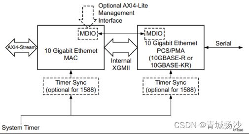
Figure 1-2: 10 Gigabit Ethernet High-Level Block Diagram
Figure 1-3 illustrates the relationship between the Open Systems Interconnection (OSI) reference model and the core. The grayed-in layers show the functionality that the core handles. Figure 1-3 also shows where the supported physical interfaces fit into the architecture.

Figure 1-3: IEEE Std 802.3-2012 Ethernet Model
Physical Coding Sublayer(PCS), coding the data stream from MAC.
Physical Medium Attachment(PMA), which is responsible for transmit/receive, serial parallel conversion.
Physical medium dependent(PMD) sublayers define the details of transmission and reception of individual bits on a physical medium. These responsibilities encompass bit timing, signal encoding, interacting with the physical medium, and the properties of the cable, optical fiber, or wire itself.
Since the PCA3.0 will be based on Versal 1902 and Vivado 2021.1, the Ethernet iP and examples below are also based on that.
Normal Transmission
Table 1‐1: AXI4-Stream Transmit Interface Signal
| Name |
I/O |
Description |
Domain Clock |
| tx_axis_tdata[31:0] |
I |
AXI4-Stream Data |
tx_core_clk |
| tx_axis_tkeep[7:0] |
I |
AXI4-Stream Data Control. |
tx_core_clk |
| tx_axis_tlast |
I |
AXI4-Stream signal indicating End of Packet. |
tx_core_clk |
| tx_axis_tvalid |
I |
AXI4-Stream Data Valid. |
tx_core_clk |
| tx_axis_tuser |
I |
AXI4-Stream User Sideband interface signal. |
tx_core_clk |
| tx_axis_tready |
O |
AXI4-Stream acknowledge signal to indicate to start the Data transfer |
tx_core_clk |
When the client wants to transmit a frame, it asserts the tx_axis_tvalid and places the data and control in tx_axis_tdata and tx_axis_tkeep in the same clock cycle. When this data is accepted by the core, indicated by tx_axis_tready being asserted, the client must provide the next cycle of data. If tx_axis_tready is not asserted by the core, the client must hold the current valid data value until it is. The end of packet is indicated to the core by tx_axis_tlast asserted for one cycle. The bits of tx_axis_tkeep are set appropriately to indicate the number of valid bytes in the final data transfer. tx_axis_tuser is also asserted to indicate a bad packet.
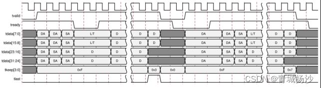
Figure 1-4: Normal Frame Transfer 32-bit
Normal Frame Reception
Table 1‐2: AXI4-Stream Receive Interface Signal
| Signal |
I/O |
Description |
Clock Domain |
| rx_axis_tdata[31:0] |
O |
AXI4-Stream Data to upper layer. Bus width depends on 64-bit or 32-bit selection. |
rx_core_clk |
| rx_axis_tkeep[3:0] |
O |
AXI4-Stream Data Control to upper layer. Bus width depends on 64-bit or 32-bit selection. |
rx_core_clk |
| rx_axis_tvalid |
O |
AXI4-Stream Data Valid |
rx_core_clk |
| rx_axis_tuser |
O |
AXI4-Stream User Sideband interface. |
rx_core_clk |
| rx_axis_tlast |
O |
XI4-Stream signal indicating an end of packet. |
rx_core_clk |
The client must be prepared to accept data at any time; there is no buffering within the core to allow for latency in the receive client.

Figure 1-5: Normal Frame Reception 32-bit
The figures below show the instantiation of various modules and their hierarchy for a single core configuration of the xxv_ethernet_0 design when the GT (serial transceiver) is outside the IP Core, that is, in the example design. This hierarchical example design is delivered when you select the Include GT subcore in example design option from the GT Selection and Configuration tab.

Figure 1-6: Single Core with GT in Example Design Hierarchy
The following figure is a block design, where 10/25G Ethernet example design connected in the IP integrator.
When the 10/25G Ethernet subsystem is added to the Vivado IP integrator, the run Block Automation IP/Core and GT (Serial transceivers) will get connected with some helper blocks as per the core configuration. There is a reset interface IP, internal to 10/25G Ethernet IP, used to release TX/RX mstreset to Versal device GT and check for TX/RX mstresetdone status and reset sequencing to GT.

Figure 1-7: 10/25G Ethernet example Block Design(MAC+PCS/PMA 32-bit)
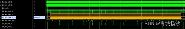


Figure 1-8: The sanity testing result of the example testbench