单片机毕业设计项目:基于单片机的浴室水温控制系统的设计
概要
基于此种情况,本课题使用温度传感器DS18B20实时测量水温,微处理器STM32F103C8T6采样水温值,并根据水温值的实时变化合理调节冷热水的进水量,当水温低于所设定温度的范围则继续加热水,如果水温高出所设定温度的范围则加凉水,使得出水始终保持在舒适的温度,即自动控制浴室水温,避免了频繁人为改变水温的麻烦,同时也在一定程度上减少了能源的消耗。为了达到预期的实验目标,本课题还进行了实物的组装,软件程序的调试等。
关键词:STM32F103C8T6单片机 DS18B20传感器 自动控制水温 太阳能热水器
一、浴室水温控制系统基本原理
2.1浴室水温控制系统总体架构
本系统的总体架构包含如下功能部分:5.0V及3.3V供电部分,主控微处理器STM32F103C8T6,调试功能接口,存储器部分,DS18B20传感器信息采集部分,串口通信部分,扩展接口功能,水泵控制执行部分。

2.2浴室水温系统总体设计流程
智能淋浴系统的总体设计流程如下。
(1)根据课题需求,确定功能模块,主要包含水温数据采集部分,冷热水进水控制部分,硬件定时部分,程序指示部分,串口数据交互部分等。
(2)根据功能模块,画原理图,PCB图,PCB图制板,购买料单,焊接调试硬件。
(3)利用STM32CubeMX软件配置微处理器的底层驱动,生成底层驱动代码。

(4)编写用户逻辑代码,如DS18B20的应用代码。
(5)调试代码,如查看水温传感器数据
二、浴室水温控制系统硬件设计
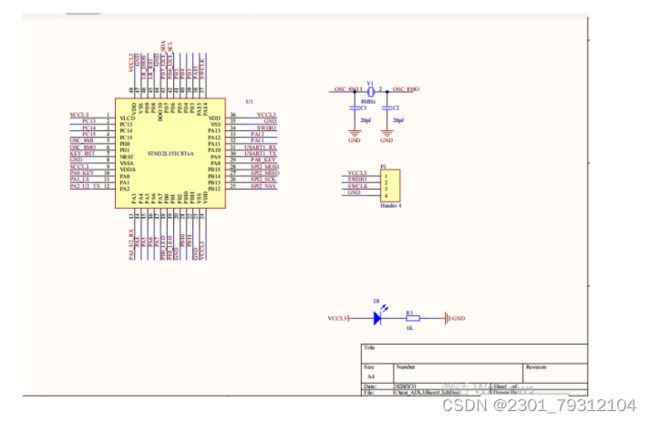
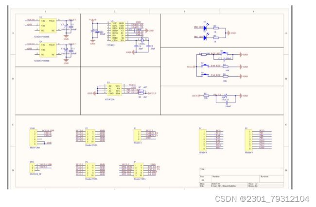
在本节中,我们主要对系统的硬件设计进行功能介绍。硬件的设计我们采用的是Altium Designer V10,主要是设计了系统的原理图和PCB版图,主要包含:供电电路,微处理器最小系统,存储电路,光敏传感器电路,TTL-UART转USB电路,SWD调试及外扩电路接口,按键电路等。
硬件电路的设计主要有:原理图器件库建立及使用,原理图器件连线,PCB器件封装库建立及使用,PCB布线,PCB板图投稿,根据BOM购买相应的器件,PCB板的焊接及调试。
三、 系统软件设计
1附录A 电路图
程序
#include "main.h"
#include "stm32f1xx_hal.h"
#include "cmsis_os.h"
#include "dma.h"
#include "i2c.h"
#include "tim.h"
#include "usart.h"
#include "gpio.h"

/* USER CODE BEGIN Includes */
#include "bsp_dwt.h"
#include "bsp_ds18b20.h"
#include "bsp_timer.h"
/* USER CODE END Includes */

/* Private variables ---------------------------------------------------------*/

/* USER CODE BEGIN PV */
/* Private variables ---------------------------------------------------------*/

/* USER CODE END PV */

/* Private function prototypes -----------------------------------------------*/
void SystemClock_Config(void);
void MX_FREERTOS_Init(void);

/* USER CODE BEGIN PFP */
/* Private function prototypes -----------------------------------------------*/

/* USER CODE END PFP */

/* USER CODE BEGIN 0 */

/* USER CODE END 0 */

/**
  * @brief  The application entry point.
  *
  * @retval None
  */
int main(void)
{
  /* USER CODE BEGIN 1 */

  /* USER CODE END 1 */

  /* MCU Configuration----------------------------------------------------------*/

  /* Reset of all peripherals, Initializes the Flash interface and the Systick. */
  HAL_Init();

  /* USER CODE BEGIN Init */

  /* USER CODE END Init */

  /* Configure the system clock */
  SystemClock_Config();

  /* USER CODE BEGIN SysInit */

  /* USER CODE END SysInit */

  /* Initialize all configured peripherals */
  MX_GPIO_Init();
  MX_DMA_Init();
  MX_USART1_UART_Init();
  MX_TIM2_Init();
  MX_I2C1_Init();
  /* USER CODE BEGIN 2 */
	bsp_InitDWT();
	bsp_InitDS18B20();
	HAL_TIM_Base_Start_IT(&htim2);
  /* USER CODE END 2 */

  /* Call init function for freertos objects (in freertos.c) */
  MX_FREERTOS_Init();

  /* Start scheduler */
  osKernelStart();

  /* We should never get here as control is now taken by the scheduler */

  /* Infinite loop */
  /* USER CODE BEGIN WHILE */
  while (1)
  {

  /* USER CODE END WHILE */

  /* USER CODE BEGIN 3 */

  }
  /* USER CODE END 3 */

}

/**
  * @brief System Clock Configuration
  * @retval None
  */
void SystemClock_Config(void)
{

  RCC_OscInitTypeDef RCC_OscInitStruct;
  RCC_ClkInitTypeDef RCC_ClkInitStruct;

    /**Initializes the CPU, AHB and APB busses clocks
    */
  RCC_OscInitStruct.OscillatorType = RCC_OSCILLATORTYPE_HSE;
  RCC_OscInitStruct.HSEState = RCC_HSE_ON;
  RCC_OscInitStruct.HSEPredivValue = RCC_HSE_PREDIV_DIV1;
  RCC_OscInitStruct.HSIState = RCC_HSI_ON;
  RCC_OscInitStruct.PLL.PLLState = RCC_PLL_ON;
  RCC_OscInitStruct.PLL.PLLSource = RCC_PLLSOURCE_HSE;
  RCC_OscInitStruct.PLL.PLLMUL = RCC_PLL_MUL9;
  if (HAL_RCC_OscConfig(&RCC_OscInitStruct) != HAL_OK)
  {
    _Error_Handler(__FILE__, __LINE__);
  }

    /**Initializes the CPU, AHB and APB busses clocks
    */
  RCC_ClkInitStruct.ClockType = RCC_CLOCKTYPE_HCLK|RCC_CLOCKTYPE_SYSCLK
                              |RCC_CLOCKTYPE_PCLK1|RCC_CLOCKTYPE_PCLK2;
  RCC_ClkInitStruct.SYSCLKSource = RCC_SYSCLKSOURCE_PLLCLK;
  RCC_ClkInitStruct.AHBCLKDivider = RCC_SYSCLK_DIV1;
  RCC_ClkInitStruct.APB1CLKDivider = RCC_HCLK_DIV2;
  RCC_ClkInitStruct.APB2CLKDivider = RCC_HCLK_DIV1;

  if (HAL_RCC_ClockConfig(&RCC_ClkInitStruct, FLASH_LATENCY_2) != HAL_OK)
  {
    _Error_Handler(__FILE__, __LINE__);
  }

    /**Configure the Systick interrupt time
    */
  HAL_SYSTICK_Config(HAL_RCC_GetHCLKFreq()/1000);

    /**Configure the Systick
    */
  HAL_SYSTICK_CLKSourceConfig(SYSTICK_CLKSOURCE_HCLK);

  /* SysTick_IRQn interrupt configuration */
  HAL_NVIC_SetPriority(SysTick_IRQn, 15, 0);
}

/* USER CODE BEGIN 4 */

/* USER CODE END 4 */

/**
  * @brief  Period elapsed callback in non blocking mode
  * @note   This function is called  when TIM4 interrupt took place, inside
  * HAL_TIM_IRQHandler(). It makes a direct call to HAL_IncTick() to increment
  * a global variable "uwTick" used as application time base.
  * @param  htim : TIM handle
  * @retval None
  */
void HAL_TIM_PeriodElapsedCallback(TIM_HandleTypeDef *htim)
{
  /* USER CODE BEGIN Callback 0 */

  /* USER CODE END Callback 0 */
  if (htim->Instance == TIM4) {
    HAL_IncTick();
  }
  /* USER CODE BEGIN Callback 1 */
	else if(htim->Instance == TIM2)
	{
		b_timerT.t2_nsNum++;
		if(b_timerT.t2_nsNum > TIMER2_NSNUM)
		{
			b_timerT.t2_nsNum = 0;
			b_timerT.t2_nsFlag = 1;
		}

		b_timerT.t2_sampleNum++;
		if(b_timerT.t2_sampleNum > TIMER2_SAMPLENUM)
		{
			b_timerT.t2_sampleNum = 0;
			b_timerT.t2_sampleFlag = 1;
		}

		b_timerT.t2_sendNum++;
		if(b_timerT.t2_sendNum > TIMER2_SENDNUM)
		{
			b_timerT.t2_sendNum = 0;
			b_timerT.t2_sendFlag = 1;
		}
	}
  /* USER CODE END Callback 1 */
}

/**
  * @brief  This function is executed in case of error occurrence.
  * @param  file: The file name as string.
  * @param  line: The line in file as a number.
  * @retval None
  */
void _Error_Handler(char *file, int line)
{
  /* USER CODE BEGIN Error_Handler_Debug */
  /* User can add his own implementation to report the HAL error return state */
  while(1)
  {
  }
  /* USER CODE END Error_Handler_Debug */
}

#ifdef  USE_FULL_ASSERT
/**
  * @brief  Reports the name of the source file and the source line number
  *         where the assert_param error has occurred.
  * @param  file: pointer to the source file name
  * @param  line: assert_param error line source number
  * @retval None
  */
void assert_failed(uint8_t* file, uint32_t line)
{
  /* USER CODE BEGIN 6 */
  /* User can add his own implementation to report the file name and line number,
     tex: printf("Wrong parameters value: file %s on line %d\r\n", file, line) */
  /* USER CODE END 6 */
}
#endif /* USE_FULL_ASSERT */

/**
  * @}
  */

/**
  * @}
  */

/************************ (C) COPYRIGHT STMicroelectronics *****END OF FILE****/


Bsp-usart.c

#include "bsp_usart.h"

/* USER CODE BEGIN Private defines */
bsp_usartType b_usartT =
{
	.u1TestBuff = "Hello USART1 !",
};

/* USER CODE END Private defines */
int fputc (int c, FILE *fp)
{
	uint8_t temp = c;
	HAL_UART_Transmit(&huart1,&temp,1,2);
	return c;
}

/**
  * @brief  Rx Transfer completed callbacks.
  * @param  huart: pointer to a UART_HandleTypeDef structure that contains
  *                the configuration information for the specified UART module.
  * @retval None
  */
void HAL_UART_RxCpltCallback(UART_HandleTypeDef *huart)
{
		__HAL_UART_FLUSH_DRREGISTER(huart);

    if(huart->Instance==USART1)
		{
			b_usartT.u1RxdBuff[b_usartT.u1RxdNum++] = b_usartT.rx1Data;
			if(b_usartT.u1RxdNum > U1_RECV_LEN-1)
			{
				b_usartT.u1RxdNum = 0;
				b_usartT.u1RxdFlag = 1;
			}
		}
}

/**
  * @brief  test for uart data recieve.
  * @param  huart: pointer to a UART_HandleTypeDef structure that contains
  *                the configuration information for the specified UART module.
  * @retval None
  */

void bsp_usartTest(void)
{
	if(b_usartT.u1RxdFlag)
	{
		b_usartT.u1RxdFlag = 0;
		HAL_UART_Transmit(&huart1,b_usartT.u1RxdBuff, U1_RECV_LEN,100);
	}
}


#include "bsp_ds18b20.h"

#define PORT_DQ			GPIOB
#define PIN_DQ			GPIO_PIN_3
#define DQ_0()			(HAL_GPIO_WritePin(PORT_DQ, PIN_DQ, GPIO_PIN_RESET))
#define DQ_1()			(HAL_GPIO_WritePin(PORT_DQ, PIN_DQ, GPIO_PIN_SET))
#define DQ_IS_LOW()	(HAL_GPIO_ReadPin(PORT_DQ, PIN_DQ) == GPIO_PIN_RESET)

void bsp_InitDS18B20(void)
{
	DQ_1();
}

uint8_t DS18B20_Reset(void)
{


	uint8_t i;
	uint16_t k;
	bsp_DelayUS(5);

	if (i >= 1)
	{
		return 0;
	}
	return 1;
}

static void DS18B20_WriteByte(uint8_t _val)
{

	uint8_t i;

	for (i = 0; i < 8; i++)
	{
		DQ_0();
		bsp_DelayUS(2);

		if (_val & 0x01)
		{
			DQ_1();
		}
		else
		{
			DQ_0();
		}
		bsp_DelayUS(60);
		DQ_1();
		bsp_DelayUS(2);
		_val >>= 1;
	}
}

static uint8_t DS18B20_ReadByte(void)
{

	uint8_t i;
	uint8_t read = 0;

	for (i = 0; i < 8; i++)
	{
		read >>= 1;

		DQ_0();
		bsp_DelayUS(3);
		DQ_1();
		bsp_DelayUS(3);

		if (DQ_IS_LOW())
		{
			;
		}
		else
		{
			read |= 0x80;
		}
		bsp_DelayUS(60);
	}

	return read;
}

int16_t DS18B20_ReadTempReg(void)
{
	uint8_t temp1, temp2;
	if (DS18B20_Reset() == 0)
	{
		return 0;
	}

	DS18B20_WriteByte(0xcc);
	DS18B20_WriteByte(0x44);
	DS18B20_Reset();

	DS18B20_WriteByte(0xcc);
	DS18B20_WriteByte(0xbe);

	temp1 = DS18B20_ReadByte();
	temp2 = DS18B20_ReadByte();

	return ((temp2 << 8) | temp1);
}

uint8_t DS18B20_ReadID(uint8_t *_id)
{
	uint8_t i;

		if (DS18B20_Reset() == 0)
	{
		return 0;
	}

	DS18B20_WriteByte(0x33);
	for (i = 0; i < 8; i++)
	{
		_id[i] = DS18B20_ReadByte();
	}

	DS18B20_Reset();

	return 1;
}

int16_t DS18B20_ReadTempByID(uint8_t *_id)
{
	uint8_t temp1, temp2;
	uint8_t i;

	DS18B20_Reset();

	DS18B20_WriteByte(0x55);
	for (i = 0; i < 8; i++)
	{
		DS18B20_WriteByte(_id[i]);
	}
	DS18B20_WriteByte(0x44);

	DS18B20_Reset();

	DS18B20_WriteByte(0x55);
	for (i = 0; i < 8; i++)
	{
		DS18B20_WriteByte(_id[i]);
	}
	DS18B20_WriteByte(0xbe);

	temp1 = DS18B20_ReadByte();
	temp2 = DS18B20_ReadByte();

	return ((temp2 << 8) | temp1);
}

uint8_t g_rom_id[8] = {0};
void test_ds18b20ID(void)
{

		uint8_t id[8];
		uint8_t ret;
		uint8_t i;

		ret = DS18B20_ReadID(id);
		if (ret == 0)
		{
			printf("δ¼ì²âµ½ DS18B20 \r\n");
			memset(g_rom_id, 0, 8);
		}
		else
		{
			printf("DS18B20 Ok, id = ");

			for (i = 0; i < 8; i++)
			{
				printf("%02X ", id[i]);
			}
			printf("\r\n");
			memcpy(g_rom_id, id, 8);
		}
}

void test_ds18b20Data(void)
{
		uint8_t m;
	int16_t reg;
	uint16_t usReg[10] = {
		0x07D0, 0x0550, 0x0191, 0x00A2, 0x0008,
		0x0000, 0xFFF8, 0xFF5E, 0xFE6F, 0xFC90};

	for (m = 0; m < 10; m++)
	{
		reg = usReg[m];
		printf("reg = 0x%04X %6d --> %-4.04f¡æ\r\n", (uint16_t)reg, reg, (float)reg / 16);
	}
}


time

#include "bsp_timer.h"

/* USER CODE BEGIN Private defines */

bsp_timerType b_timerT;
/* USER CODE END Private defines */

/**
  * @brief  pwm set value.
  * @param  bsp_timerType b_timerT
  * @retval None
*/
/*
void app_pwmSetValue(bsp_timerType *b_timerT)
{
	TIM_OC_InitTypeDef sConfigOC;

	sConfigOC.OCMode = TIM_OCMODE_PWM1;
  sConfigOC.Pulse = b_timerT->pwm_value;
  sConfigOC.OCPolarity = TIM_OCPOLARITY_HIGH;
  sConfigOC.OCFastMode = TIM_OCFAST_DISABLE;
  if (HAL_TIM_PWM_ConfigChannel(&htim3, &sConfigOC, TIM_CHANNEL_1) != HAL_OK)
  {
    _Error_Handler(__FILE__, __LINE__);
  }

  HAL_TIM_PWM_Start(&htim3, TIM_CHANNEL_1);
}
*/
/**
  * @brief  pwm display.
  * @param  bsp_timerType b_timerT
  * @retval None
*/
/*
void app_pwmDisp(bsp_timerType*b_timerT)
{
	if(b_timerT->pwm_value == 0) b_timerT->pwm_step = 10;
	if(b_timerT->pwm_value == 5000) b_timerT->pwm_step = -10;

	b_timerT->pwm_value += b_timerT->pwm_step;
	app_pwmSetValue(b_timerT);
}
*/
四、 总结
在此项课题项目的研究开发过程中,我熟悉了工程开发的整体流程,对各部分应注意的问题更加留心,使得对于工程项目的开发有了更深入的了解,为将来踏入工作中实现真正的项目开发打下了一定的基础。
在此项课题研究中,对于软件代码的编写,在很大程度上对C语言编程我有了更深入的认识与理解,进一步熟悉了C语言的使用方法和使用场景,同时进一步熟悉了C语言代码的调用及模块化编程理念。
五、 文章目录
目 录
摘 要 I
Abstract II
1 引 言 1
1.1 论文的选题背景及意义 1
1.1.1 国内外发展情况 2
2 浴室水温控制系统基本原理 4
2.1 浴室水温控制系统总体架构 4
2.2 浴室水温控制系统各部分功能 4
2.2.1 主控微处理器部分 4
2.2.2 电源部分 6
2.2.3 调试及接口外扩部分 6
2.2.4 串口通信部分 6
2.3 DS18B20水温传感器部分 7
2.4 浴室水温系统总体设计流程 10
3 浴室水温控制系统硬件设计 13
3.1 最小系统硬件功能介绍 13
3.1.1 供电电路 13
3.1.2 微处理器电路 14
3.1.3 USB转TTL-UART电路 15
3.1.4 按键电路 16
3.1.5 LED指示灯电路 16
3.2 水温传感器电路 17
4 浴室水温控制系统软件设计 18
4.1 STM32CubeMX硬件驱动配置软件介绍 18
4.2 STM32CubeMX硬件底层配置 19
4.3 生成底层硬件的驱动代码 23
5 恒温系统应用逻辑代码实现 25
5.1 Keil-MDK5软件介绍 25
5.2 用户逻辑代码实现 26
6 结 论 27
参考文献 28
附录A 电路图 29
附录B 源程序 30
致 谢 44


