S5PV210裸机(八):I2C
本文主要探讨210的I2C相关知识。
I2C
物理接口:SCL + SDA
SCL:时钟线传输CLK信号(KHz)
SDA: 数据线传输通信数据
通信特征:串行、同步、非差分、低速率
主设备发起通信,从设备按照I2C协议接受信息并响应
同一设备可以是主设备,也可是从设备
主设备可挂载多从设备(主从地址唯一)在总线上,实现一对多通信,但同一时间内主设备只能和一台从设备通信
用途:SoC和外设间通信(EEPROM、sensor)
I2C通信时序
时序:通信线上按时间顺序电平发生变化且变化对通信具有意义
I2C总线状态:空闲状态、忙态
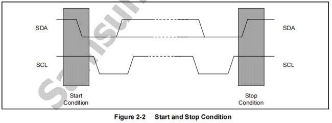
两相邻通信周期间是空闲态(其余忙态),通信周期由起始位开始,结,中间为通信数据
起始是时间段:SCL维持高电平,SDA由高到低
结束是时间段:SCL维持高电平,SDA由低到高
210的I2C
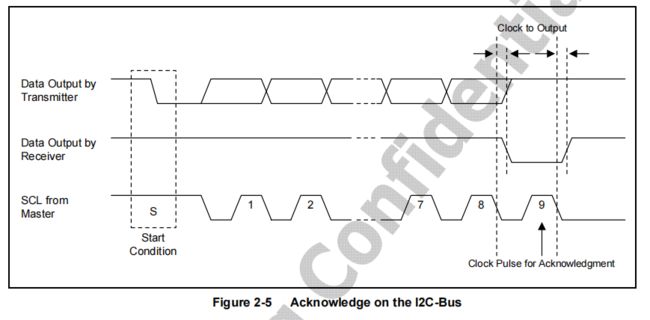
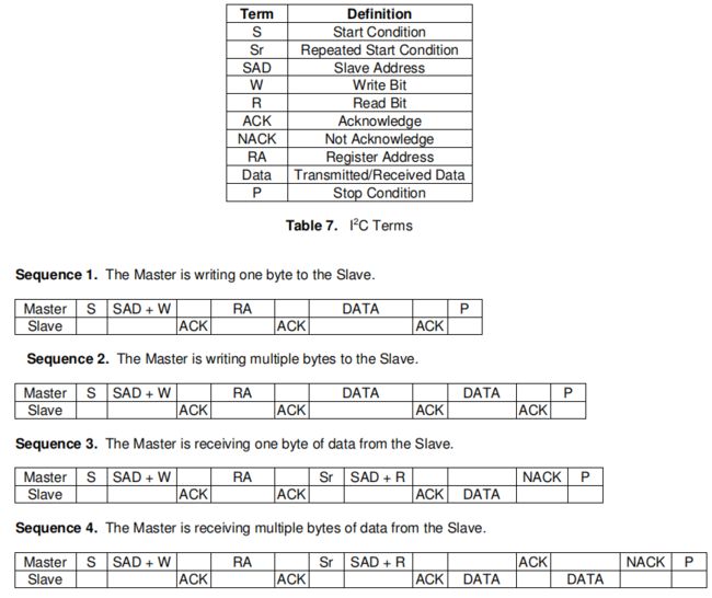
主设备在一通信周期广播发送8位从设备地址(7位从地址,1位表示读写,0主写1主接收)到总线,对应从设备响应
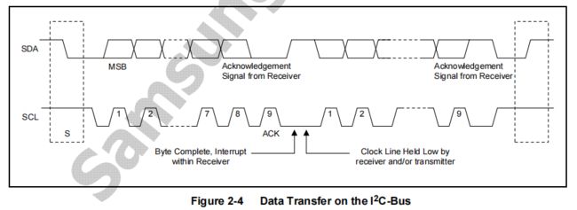
发送方发送一段数据,接收方接收数据响应ACK(1bit),无响应则未收到
I2C通信时每次传输有效数据都1个字节(8位)
移位寄存器将数据一位位从SDA线上去发送/接收
时钟源是PCLK_PSYS,内部分频得到I2C控制器CLK,通过SCL线传给从设备
210的I2C寄存器(SoC)
gpio

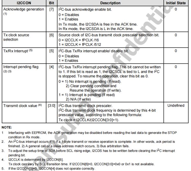
I2CCON + I2CSTAT:产生通信时序,I2C接口配置 ,时钟一级分频I2CCON的bit6(等于PCLK/16或者PCLK/512)二级分频系数为[1,16]:65000KHz/512/4=31KHz
I2CADD:从设备地址
210的gsensor(KXTE9)
gsensor供电由PWMTOUT3控制,低电平不工作,高电平工作
gsensor的SDA和SCL接S5PV210的I2C端口0
KXTE9的I2C地址为0b0001111(0x0f),最高支持400KHz
主设备读取gsensor信息时SAD是:0b00011111(0x1F),读时SAD应该是:0b00011110(0x1E)
寄存器
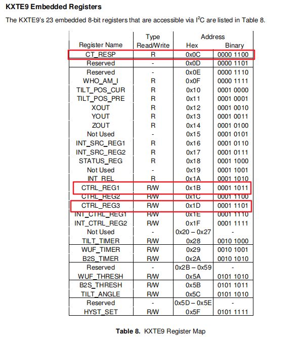
CT_RESP (0x0C)
默认为0x55,当把CTRL_3的bit4为1,读取0xAA,第二次读自动变为0x55,用于测试通信是否成功
CTRL_1 (0x1B)
写入0x98,KXTE9 为操作模式(默认为待机),数据传输速率设为40Hz
CTRL_3 (0x1D)
CTRL_3的bit4为1,读取CT_RESP得到0xAA,第二次读自动变为0x55,用于测试通信是否成功
流程
210的I2C通信流程
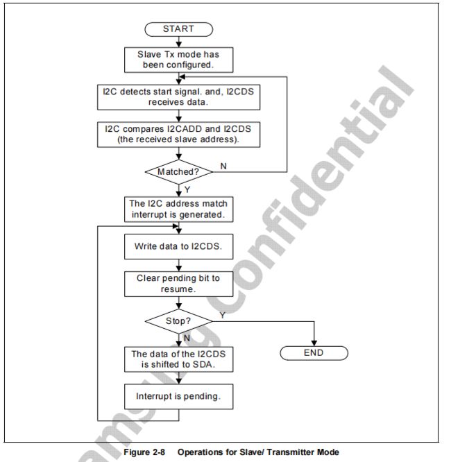
主发送

I2C通信功能(主)
I2C控制器初始化:s3c24xx_i2c_init(初始化GPIO,设置IRQEN和ACKEN、设置时钟)
/* s3c24xx_i2c_init
 *
 * initialise the controller, set the IO lines and frequency
*/

static int s3c24xx_i2c_init(struct s3c24xx_i2c *i2c)
{
	unsigned long iicon = S3C2410_IICCON_IRQEN | S3C2410_IICCON_ACKEN;
	struct s3c2410_platform_i2c *pdata;
	unsigned int freq;

	/* get the plafrom data */

	pdata = i2c->dev->platform_data;

	/* inititalise the gpio */

	if (pdata->cfg_gpio)
		pdata->cfg_gpio(to_platform_device(i2c->dev));

	/* write slave address */

	writeb(pdata->slave_addr, i2c->regs + S3C2410_IICADD);

	dev_dbg(i2c->dev, "slave address 0x%02x\n", pdata->slave_addr);

	writel(iicon, i2c->regs + S3C2410_IICCON);

	/* we need to work out the divisors for the clock... */

	if (s3c24xx_i2c_clockrate(i2c, &freq) != 0) {
		writel(0, i2c->regs + S3C2410_IICCON);
		dev_err(i2c->dev, "cannot meet bus frequency required\n");
		return -EINVAL;
	}

	/* todo - check that the i2c lines aren't being dragged anywhere */

	dev_dbg(i2c->dev, "bus frequency set to %d KHz\n", freq);
	dev_dbg(i2c->dev, "S3C2410_IICCON=0x%02lx\n", iicon);

	dev_dbg(i2c->dev, "S3C2440_IICLC=%08x\n", pdata->sda_delay);
	writel(pdata->sda_delay, i2c->regs + S3C2440_IICLC);

	return 0;
}
I2C控制器开始读写:s3c24xx_i2c_message_start
/* s3c24xx_i2c_message_start
 *
 * put the start of a message onto the bus
*/

static void s3c24xx_i2c_message_start(struct s3c24xx_i2c *i2c,
				      struct i2c_msg *msg)
{
	unsigned int addr = (msg->addr & 0x7f) << 1;
	unsigned long stat;
	unsigned long iiccon;

	stat = 0;
	stat |=  S3C2410_IICSTAT_TXRXEN;

	if (msg->flags & I2C_M_RD) {
		stat |= S3C2410_IICSTAT_MASTER_RX;
		addr |= 1;
	} else
		stat |= S3C2410_IICSTAT_MASTER_TX;

	if (msg->flags & I2C_M_REV_DIR_ADDR)
		addr ^= 1;

	/* todo - check for wether ack wanted or not */
	s3c24xx_i2c_enable_ack(i2c);

	iiccon = readl(i2c->regs + S3C2410_IICCON);
	writel(stat, i2c->regs + S3C2410_IICSTAT);

	dev_dbg(i2c->dev, "START: %08lx to IICSTAT, %02x to DS\n", stat, addr);
	writeb(addr, i2c->regs + S3C2410_IICDS);

	/* delay here to ensure the data byte has gotten onto the bus
	 * before the transaction is started */

	ndelay(i2c->tx_setup);

	dev_dbg(i2c->dev, "iiccon, %08lx\n", iiccon);
	writel(iiccon, i2c->regs + S3C2410_IICCON);

	stat |= S3C2410_IICSTAT_START;
	writel(stat, i2c->regs + S3C2410_IICSTAT);
}
I2C控制器结束读写:s3c24xx_i2c_stop
static inline void s3c24xx_i2c_stop(struct s3c24xx_i2c *i2c, int ret)
{
	unsigned long iicstat = readl(i2c->regs + S3C2410_IICSTAT);

	dev_dbg(i2c->dev, "STOP\n");

	/* stop the transfer */
	iicstat &= ~S3C2410_IICSTAT_START;
	writel(iicstat, i2c->regs + S3C2410_IICSTAT);

	i2c->state = STATE_STOP;

	s3c24xx_i2c_master_complete(i2c, ret);
	s3c24xx_i2c_disable_irq(i2c);
}
demo:
编写i2c读写
start.S
#define WTCON           0xE2700000
#define SVC_STACK       0xd0037d80

.global _start

_start:
        //close watchDog
        ldr r0,=WTCON
        ldr r1,=0x0
        str r1,[r0]

        //init SVC stack
        ldr sp,=SVC_STACK

        //init icache
        mrc p15,0,r0,c1,c0,0
        bic r0,r0,#(1<<12)      //close icache
        orr r0,r0,#(1<<12)      //open icache
        mcr p15,0,r0,c1,c0,0

        //use func
        bl main

        b .
main.c
#include "i2c_gsensor.h"
#include "uart_printf.h"

int main()
{
        //init uart
        init_uart();

        //init i2c
        i2c_init();

        //read and write i2c
        gsensor_read_write();
        return 0;
}
uart_printf.h
void init_uart();uart_printf.c
#define GPA0CON         0xE0200000

#define ULCON0          0xE2900000
#define UCON0           0xE2900004
#define UFCON0          0xE2900008
#define UMCON0          0xE290000C
#define UTRSTAT0        0xE2900010
#define UTXH0           0xE2900020
#define URXH0           0xE2900024
#define UBRDIV0         0xE2900028
#define UDIVSLOT0       0xE290002C

#define rGPA0CON        (*(volatile unsigned int *)GPA0CON)
#define rULCON0         (*(volatile unsigned int *)ULCON0)
#define rUCON0          (*(volatile unsigned int *)UCON0)
#define rUFCON0         (*(volatile unsigned int *)UFCON0)
#define rUMCON0         (*(volatile unsigned int *)UMCON0)
#define rUTRSTAT0       (*(volatile unsigned int *)UTRSTAT0)
#define rUTXH0          (*(volatile unsigned int *)UTXH0)
#define rURXH0          (*(volatile unsigned int *)URXH0)
#define rUBRDIV0        (*(volatile unsigned int *)UBRDIV0)
#define rUDIVSLOT0      (*(volatile unsigned int *)UDIVSLOT0)

//init uart
void init_uart()
{
        //set gpio as uart(rx,tx)
        rGPA0CON &= ~(0xff);
        rGPA0CON |= ((1<<2)|(1<<5));

        //set uart base configure(mode)
        rULCON0 = 0x3;
        rUCON0 = 0x5;
        rUMCON0 = 0;
        rUFCON0 = 0;

        //set uart baud
        //DIV_VAL = (PCLK / (bps x 16))-1
        //(66000000 /(115200 * 16)) -1 = 34.8
        rUBRDIV0 = 34;

        //set uart baud calibration
        //0.8 * 16 = 13,check 210 table
        rUDIVSLOT0 = 0xdfdd;
}


//send data
void putc(char data)
{
        while (!(rUTRSTAT0 & (1<<1)));
        rUTXH0 = data;
}

//receive data
char getc()
{
        while (!(rUTRSTAT0 & (1<<0)));
        return (rURXH0 & 0xff);
}
i2c_gsensor.h
void i2c_init();

void gsensor_read_write();
i2c_gsensor.c
#include "uart_printf.h"
#include "stdio.h"

#define  GPD1CON        0xE02000C0
#define  rGPD1CON       (*(volatile unsigned int *)0xE02000C0)

#define  I2CCON0        0xE1800000
#define  I2CSTAT0       0xE1800004
#define  I2CADD0        0xE1800008
#define  I2CDS0         0xE180000C
#define  rI2CCON0       (*(volatile unsigned int *)0xE1800000)
#define  rI2CSTAT0      (*(volatile unsigned int *)0xE1800004)
#define  rI2CADD0       (*(volatile unsigned int *)0xE1800008)
#define  rI2CDS0        (*(volatile unsigned int *)0xE180000C)

#define  WRITE_GSENSOR  0x1E
#define  READ_GSENSOR   0x1F

#define  CT_RESP_ADDR   0x0C
#define  CTRL_REG2_ADDR 0x1C


static void dealy_time()
{
        volatile unsigned int num = 100;
        while(num--);
}

void i2c_init()
{
        printf("start i2c init\r\n");
        //set gpio as i2c output
        rGPD1CON &= ~(0xff);
        rGPD1CON |= (0x22);

        //enable interrupt
        rI2CCON0 |= (1<<5);

        //set i2c clock,65Mhz / 512 /2 = 31Khz
        rI2CCON0 |= (1<<6);
        rI2CCON0 &= ~(0x0f);
        rI2CCON0 |= (1<<0);

        //enable serial output
        rI2CSTAT0 |= (1<<4);
        printf("i2c init end\r\n");
}

static void i2c_start_send_get(int num)
{
        //enable ack
        rI2CCON0 |= (1<<7);
        //judge send or get ,0 is send,1 is get
        if(num == 0)
        {
                //send gsensor addr and mode(read or read)
                rI2CDS0 = WRITE_GSENSOR;
                //start send
                rI2CSTAT0 = 0xF0;
        }
        else
        {
                //send gsensor addr and mode(read or read)
                rI2CDS0 = READ_GSENSOR;
                //start send
                rI2CSTAT0 = 0xB0;
        }
        //hang on  interrupt
        while((rI2CCON0 & (1<<4)) == 0);
                dealy_time();
}

static void i2c_restart_send_get(int num)
{
        //judge send or get ,0 is send,1 is get
        if(num == 0)
        {
                //send gsensor addr and mode(read or read)
                rI2CDS0 = WRITE_GSENSOR;
                //start send
                rI2CSTAT0 = 0xF0;
        }
        else
        {
                //send gsensor addr and mode(read or read)
                rI2CDS0 = READ_GSENSOR;
                //start send
                rI2CSTAT0 = 0xB0;
        }
        //clear interrupt
        rI2CCON0 &= ~(1<<4);
        //hang on  interrupt
        while((rI2CCON0 & (1<<4)) == 0);
        dealy_time();
}

static void i2c_send(unsigned char data)
{
        rI2CDS0 = data;
        //clear interrupt
        rI2CCON0 &= ~(1<<4);
        //hang on interrupt
        while((rI2CCON0 & (1<<4)) == 0)
                dealy_time();
}

static unsigned char i2c_get()
{
        //disable ack
        rI2CCON0 &= ~(1<<7);
        //clear interrupt
        rI2CCON0 &= ~(1<<4);
        //hang on  interrupt
        while((rI2CCON0 & (1<<4)) == 0);
                dealy_time();
        return  rI2CDS0;
}

static void i2c_stop_send_get(int num)
{
        //judge send or get ,0 is send,1 is get
        if(num == 0)
        {
                rI2CSTAT0 = 0xD0;
        }
        else
        {
                rI2CSTAT0 = 0x90;
        }
        //clear interrupt
        rI2CCON0 &= ~(1<<4);
        dealy_time();
}

void gsensor_read_write()
{
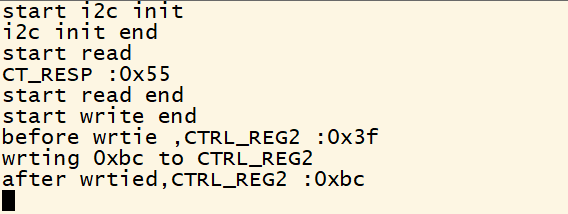
        printf("start read\r\n");
        volatile unsigned char get = 0;

        i2c_start_send_get(0);
        i2c_send(CT_RESP_ADDR);
        i2c_restart_send_get(1);
        get = i2c_get();
        i2c_stop_send_get(0);
        printf("CT_RESP :0x%x\r\n",get);
        printf("start read end\r\n",get);

        printf("start write end\r\n",get);
        i2c_start_send_get(0);
        i2c_send(CTRL_REG2_ADDR);
        i2c_restart_send_get(1);
        get = i2c_get();
        i2c_stop_send_get(0);
        printf("before wrtie ,CTRL_REG2 :0x%x\r\n",get);

        printf("wrting 0xbc to CTRL_REG2\r\n");
        i2c_start_send_get(0);
        i2c_send(CTRL_REG2_ADDR);
        i2c_send(0xbc);
        i2c_restart_send_get(1);

        i2c_start_send_get(0);
        i2c_send(CTRL_REG2_ADDR);
        i2c_restart_send_get(1);
        get = i2c_get();
        i2c_stop_send_get(0);
        printf("after wrtied,CTRL_REG2 :0x%x\r\n",get);

}
link.lds
SECTIONS
{
        . = 0xd0020010;

        .text :
        {
                start.o
                * (.text)
        }

        .data :
        {
                * (.data)
        }

        bss_start = .;

        .bss :
        {
                * (.bss)
        }
}
Makefile
CC      =       arm-linux-gcc
LD      =       arm-linux-ld
OBJCOPY =       arm-linux-objcopy
OBJDUMP =       arm-linux-objdump

INCDIR  := $(shell pwd)

#预处理器的flag,flag就是编译器可选的选项
CPPFLAGS  := -nostdlib -nostdinc -I$(INCDIR)/include
#C编译器的flag
CFLAGS    := -Wall -O2 -fno-builtin

export CC LD OBJCOPY OBJDUMP CPPFLAGS CFLAGS

objs      := start.o uart_printf.o main.o i2c_gsensor.o
objs      += lib/libc.a

led.bin:$(objs)
        $(LD) -Tlink.lds -o i2c.elf $^
        $(OBJCOPY) -O binary i2c.elf i2c.bin
        $(OBJDUMP) -D i2c.elf > i2c.dis
        gcc mkv210.c -o mkv210
        ./mkv210 i2c.bin sd.bin

lib/libc.a:
        cd lib;  make;  cd ..

%.o:%.S
        $(CC) $(CPPFLAGS) $(CFLAGS) -o $@ $< -c

%.o:%.c
        $(CC) $(CPPFLAGS) $(CFLAGS) -o $@ $< -c

clean:
        rm *.o *.elf *.bin *.dis mkv210 -f
        cd lib; make clean; cd ..
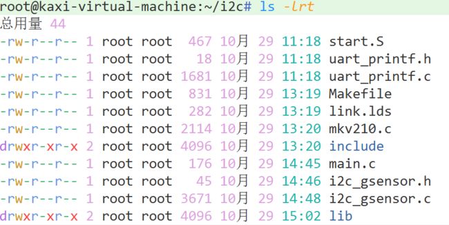
文件示例:
结果示例:

