HCIA实验
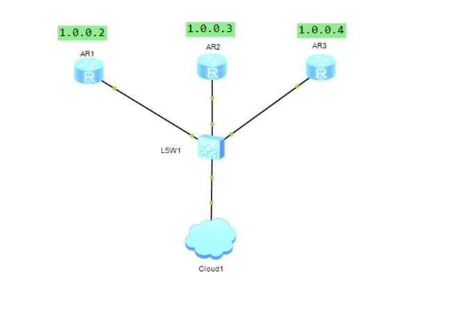
1、Telnet实验
要求:
1,配置三台路由器的主机名,IP地址
2,配置R1为Password认证,级别=15
3,配置R2为AAA认证,用户名为hcip,级别=1
4,配置R3为AAA认证,用户名为hcip,级别=2
拓扑图:
配置命令:
AR1
sys
sysname R1
int g0/0/0
ip add 1.0.0.2 24
q
user-interface vty 0 4
user privilege level 15
set authentication password cipher hcia
AR2
sys
sysname R2
int g0/0/0
ip add 1.0.0.3 24
q
user-interface vty 0 4
authentication-mode aaa
user privilege level 1
aaa
local-user hcip password chipher passwd
local-user hcip privilege level 1
loacal-user hcip service-type telnet
AR3
sys
sysname R3
int g0/0/0
ip add 1.0.0.4 24
q
user-interface vty 0 4
authentication-mode aaa
user privilege level 2
aaa
local-user hcip password chipher passwd
local-user hcip privilege level 2
local-user hcip service-type telnet
验证:
R3Telnet登录R1
telnet 1.0.0.2
  Press CTRL_] to quit telnet mode
  Trying 1.0.0.2 ...
  Connected to 1.0.0.2 ...

Login authentication

Password:
R1Telnet登录R3
telnet 1.0.0.4
  Press CTRL_] to quit telnet mode
  Trying 1.0.0.4 ...
  Connected to 1.0.0.4 ...

Login authentication

Username:hcip
Password:
2、子网划分实例
某公司共有生产部、销售部、财务部、客服部四个部门,每个部门的主机数最多不超过 50台。若该公司获得了一个C类地址192.168.100.0/24,应该如何划分子网呢?


划分4个子网,因为借了两位主机号,所以子网掩码是:
24+2=26位
二进制:11111111.11111111.11111111.11000000
十进制:255.255.255.192
| 部门 | 网段 | 子网掩码 | 有效主机数 |
|---|---|---|---|
| 生产部 | 192.168.100.1~192.168.100.62 | 255.255.255.192 | 62 |
| 销售部 | 192.168.100.65~192.168.100.126 | 255.255.255.192 | 62 |
| 财务部 | 192.168.100.129~192.168.100.190 | 255.255.255.192 | 62 |
| 客户部 | 192.168.100.193~192.168.100.254 | 255.255.255.192 | 62 |
| 部门 | 网络号 | 广播地址 |
|---|---|---|
| 生产部 | 192.168.100.0 | 192.168.100.63 |
| 销售部 | 192.168.100.64 | 192.168.100.127 |
| 财务部 | 192.168.100.128 | 192.168.100.191 |
| 客户部 | 192.168.100.192 | 192.168.100.255 |
3、静态路由实验
让三个PC互相通信

配置命令
AR1
sys
sysname R1
int g0/0/0
ip add 1.0.0.254 24
int g0/0/1
ip add 12.0.0.1 24
ip route-s 2.0.0.0 24 12.0.0.2
ip route-s 3.0.0.0 24 12.0.0.2
ip route-s 23.0.0.0 24 12.0.0.2
AR2
sys
sysname R2
int g0/0/0
ip add 12.0.0.2 24
int g0/0/1
ip add 2.0.0.254 24
int g0/0/2
ip add 23.0.0.2 24
ip route-s 1.0.0.0 24 12.0.0.1
ip route-s 3.0.0.0 24 23.0.0.3
AR3
sys
sysname R3
int g0/0/0
ip add 23.0.0.3 24
int g0/0/1
ip add 3.0.0.254 24
ip route-s 1.0.0.0 24 23.0.0.2
ip route-s 2.0.0.0 24 23.0.0.2
ip route-s 12.0.0.0 24 23.0.0.2
常用命令
查看接口IP地址
display ip int brief
查看接口简要信息
display interface brief
查看路由表
display ip routing-table
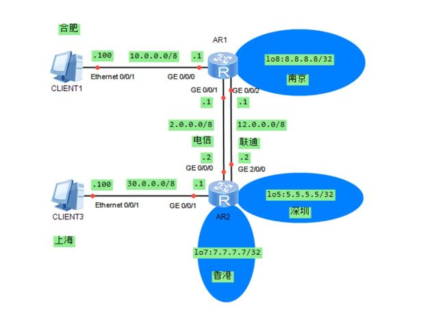
4、静态浮动缺省路由实验
要求:
1,根据拓扑信息配置主机名和IP地址
2,R1使用缺省路由去往香港和深圳,要求负载分担
3,R1使用明确的静态路由去往上海,要求优先走电信的线路
4,R2使用缺省路由去往合肥和南京,要求优先走联通的线路
配置命令
R1
sys
sysname R1
int g0/0/0
ip add 10.0.0.1 8
int g0/0/1
ip add 2.0.0.1 8
int g0/0/2
ip add 12.0.0.1 8
int lo8
ip add 8.8.8.8 32
ip route-s 0.0.0.0 0 12.0.0.2 preference 60
ip route-s 0.0.0.0 0 2.0.0.2  preference  60
ip route-s 30.0.0.100 8 2.0.0.2 preference 100
R2
sys
sysname R2
int g0/0/0
ip add 2.0.0.2 8
int g0/0/1
ip add 30.0.0.1 8
int g2/0/0
ip add 12.0.0.2 8
int lo5
ip add 5.5.5.5 32
int lo7
ip add 7.7.7.7 32
ip route-s 0.0.0.0 0 2.0.0.1 preference 60
ip route-s 0.0.0.0 0 12.0.0.1 preference 100
5、OSPF综合实验
要求:
1,配置主机名和地址
2,配置OSPF
3,手动配置RID
4,要求R1为DR,R2为BDR
5,R3和R4之间启用MD5认证
6,验证R1到4.4.4.4的开销
7,R8模拟运营商网络
8,不使用NAT
9,所有路由器可以访问8.8.8.8/32

配置命令
OSPF配置优先级的命令
ospf dr-priority命令用来设置接口在选举DR时的优先级。
undo ospf dr-priority命令用来恢复其缺省值。
命令格式
ospf dr-priority number
undo ospf dr-priority
参数含义
number:接口在选举DR或BDR时的优先级。其值越大,优先级越高。整数形式,取值范围是0~255;默认是1。
R1
sys
sysname R1
int g0/0/0
ip add 192.168.1.1 24
ospf dr-pri 200
ospf 1 route 1.1.1.1
area 0
network 192.168.1.1 0.0.0.0
R2
sys
sysname R2
int g0/0/0
ip add 192.168.1.2 24
ospf dr-pri 100
ospf 1 rout 2.2.2.2
area 0
network 192.168.1.2 0.0.0.0
R3
sys
sysname R3
int g0/0/0
ip add 192.168.1.3 24
int s4/0/0
ip add 34.0.0.3 24
ospf 1 route 3.3.3.3
area 0
network 192.168.1.3 0.0.0.0
network 34.0.0.3 0.0.0.0
R4
sys
sysname R4
int g0/0/0
ip add 48.0.0.4 24
int s4/0/0
ip add 34.0.0.4 24
int lo4
ip add 4.4.4.4 32
ospf 1 rout 4.4.4.4
default-route-advertise
area 0
network 34.0.0.4 0.0.0.0
network 4.4.4.4 0.0.0.0
ip route-s 0.0.0.0 0 48.0.0.8
R6
sys
sysname R6
int g0/0/0
ip add 192.168.1.6 24
ospf 1 rout 6.6.6.6
area 0
network 192.168.1.6 0.0.0.0
R8
sys
sysname R8
int g0/0/0
ip add 48.0.0.8 24
int lo8
ip add 8.8.8.8 32
ip route-s 0.0.0.0 0 48.0.0.4
⭐️
重启OSPF进程
reset ospf [进程ID]
当外部路由存在缺省路由时,即引入并在OSPF区域内泛宏
default-route-advertise
无论是否存在缺省路由,都会生成一条外部路由在OSPF区域内泛宏,此种方法为引入缺省路由
default-route-advertise always
设置接口在选举DR时的优先级,值越大优先级越高,取值范围0~255
ospf dr-priority 200
6、VLAN基础实验
要求:
配置VLAN
完成VLAN 10和VLAN 100间的通讯
完成VLAN 20和VLAN 200间的通讯

LSW1
sys
sysname LSW1
vlan batch 10 20 100 200
int g0/0/1
port link-type hybrid
port hybrid pvid vlan 10
port hybrid untagged vlan 10 100

int g0/0/2
port link-type hybrid
port hybrid pvid vlan 20
port hybrid untagged vlan 20 200


int g0/0/3
port link-type hybrid
port hybrid tagged vlan 10 20 100 200
LSW2
sys
sysname LSW2
vlan batch 10 20 100 200
int g0/0/1
port link-type hybrid
port hybrid pvid vlan 10
port hybrid untagged vlan 10 100

int g0/0/2
port link-type hybrid
port hybrid pvid vlan 20
port hybrid untagged vlan 20 200

int g0/0/3
port link-type hybrid
port hybrid tagged vlan 10 100 20 200
LSW3
sys
sysname LSW3
vlan batch 10 20 100 200

int g0/0/1
port link-type hybrid
port hybrid tagged vlan  10 100 20 200

int g0/0/2
port link-type hybrid
port hybrid tagged vlan  10 100 20 200

int g0/0/3
port link-type hybrid
port hybrid pvid vlan 100
port hybrid untagged vlan 10 100

int g0/0/4
port link-type hybrid
port hybrid pvid vlan 200
port hybrid untagged vlan 200 20
7、VLAN综合实验一
配置VLAN、VLAN间路由、OSPF让所有设备互相通信

基础配置
LSW1
sys
sysname LSW1
vlan batch 10 20
int e0/0/1
port link-type access
port default vlan 10

int e0/0/2
port link-type access
port default vlan 20

int e0/0/3
port link-type trunk
port trunk allow-pass vlan 10 20
LSW2
sys
sysname LSW2
vlan batch 10 20 23
int vlanif 10
ip add 192.168.10.254 24
int vlanif 20
ip add 192.168.20.254 24
int g0/0/1
port link-type trunk
port trunk allow-pass vlan 10 20
int g0/0/2
port link-type access
port default vlan 23
quit
int vlanif 23
ip add 23.0.0.2 24
LSW3
sys
sysname LSW3
vlan batch 23 13
int g0/0/1
port link-type access
port default vlan 23
int g0/0/2
port link-type access
port default vlan 13
int vlanif23
ip add 23.0.0.3 24
int vlan13
ip add 13.0.0.3 24
AR1
sys
sysname AR1
int g0/0/0
ip add 13.0.0.1 24
int g0/0/1.100
dot1q termination vid 100
ip add 192.168.100.254 24
arp broadcast enable
int g0/0/1.200
dot1q termination vid 200
ip add 192.168.200.254 24
arp broadcast enable
LSW4
sys
sysname LSW4
vlan batch 100 200
int g0/0/1
port link-type trunk
port trunk allow-pass vlan 100 200
int g0/0/2
port link-type access
port default vlan 200
int g0/0/3
port link-type access
port default vlan 100
使用OSPF让全网通
AR1
ospf 1 router-id 1.1.1.1
area 0
net 192.168.100.254 0.0.0.255
net 192.168.200.254 0.0.0.255
net 13.0.0.1 0.0.0.255
LSW3
ospf 1 router-id 3.3.3.3
area 0
net 13.0.0.3 0.0.0.255
net 23.0.0.3 0.0.0.255
LSW2
ospf 1 router-id 2.2.2.2
area 0
net 23.0.0.2 0.0.0.255
net 192.168.10.254 0.0.0.255
net 192.168.20.254 0.0.0.255
验证命令
验证VLAN信息
display vlan
验证接口VLAN
display port vlan
显示OSPF邻居信息
display ospf peer
查看OSPF路由信息
display ospf routing
8、VLAN综合实验二

LSW1
sys
sysname LSW1
vlan batch 10 20
int g0/0/2
port link-type access
port default vlan 10
int g0/0/3
port link-type access
port default vlan 20
int g0/0/1
port link-type trunk
port trunk allow-pass vlan 10 20
AR1
sys
sysname AR1
int g0/0/0.10
dot1q termination vid 10
ip add 192.168.10.254 24
arp broadcast enable
int g0/0/0.20
dot1q termination vid 20
ip add 192.168.20.254 24
arp broadcast enable
int g0/0/1
ip add 12.0.0.1 24
LSW2
sys
sysname LSW2
vlan batch 30 40
int g0/0/2
port link-type access
port default vlan 30
int g0/0/3
port link-type access
port default vlan 40
int g0/0/1
port link-type  access
port  default vlan 1
int vlanif 1
ip add 172.16.12.1 24
int vlanif 30
ip add 192.168.30.254 24
int vlan 40
ip add 192.168.40.254 24
AR2
 sys
 sysname AR2
 int g0/0/1
 ip add 12.0.0.2 24
 int g0/0/0
 ip add 172.16.12.2 24
OSPF
AR1
ospf 1 router-id 1.1.1.1
area 0
network 192.168.10.254 0.0.0.255
network 192.168.20.254 0.0.0.255
network 12.0.0.1 0.0.0.255
AR2
ospf 1 router-id 2.2.2.2
area 0
network 12.0.0.2 0.0.0.255
network 172.16.12.2 0.0.0.255
LSW2
ospf 1 router-id 3.3.3.3
area 0
network 172.16.12.1 0.0.0.255
network 192.168.30.254 0.0.0.255
network 192.168.40.254 0.0.0.255
9、VLAN综合实验三

LSW1
sys
sysname LSW1
vlan batch 10 20
int e0/0/1
port link-type access
port default vlan 10
int e0/0/2
port link-type access
port default vlan 20
int e0/0/3
port link-type trunk
port trunk allow-pass vlan 10 20
LSW2
sys
sysname LSW2
vlan batch 10 20 23
int g0/0/1
port link-type trunk
port trunk allow-pass vlan 10 20
int g0/0/2
int vlanif 1
ip add 23.0.0.1 24
int vlanif 10
ip add 192.168.10.254 24
int vlanif 20
ip add 192.168.20.254 24
LSW3
sys
sysname LSW3
vlan batch 13 23
int g0/0/1
port link-type access
port default vlan 23
int g0/0/2
port link-type access
port default vlan 13
int vlanif 23
ip add 23.0.0.2 24
int vlanif 13
ip add 13.0.0.2 24
AR1
sys
sysname AR1
int g0/0/0
ip add 13.0.0.1 24
int loopback 1
ip add 1.1.1.1 32
OSPF
AR1
ospf 1 router-id 1.1.1.1
area 0
net 13.0.0.1 0.0.0.255
LSW3
ospf 1 router-id 3.3.3.3
area 0
net 13.0.0.2 0.0.0.255
net 23.0.0.2 0.0.0.255
LSW2
ospf 1 router-id 2.2.2.2
area 0
net 23.0.0.1 0.0.0.255
net 192.168.10.254 0.0.0.255
net 192.168.20.254 0.0.0.255
10、STP实验
选举根桥,在交换网络选举一个根桥
STP在交换网络中开始工作后都会想网络中发送配置BPDU。配置BPDU中包含了交换机自己的桥。
网络中拥有最小桥的ID的交换机成为根桥
在一个连续的STP网络中只会存在一个根桥
根桥的角色是可抢占的
为了确保交换网络的稳定,建议提前规划STP组网,并将规划为根桥的交换机的桥优先级设置为最小值o。

在每台非根桥交换机上选举一个根端口
每一台非根桥交换机都会在自己的接口中选举出一个接口。非根桥交换机上有且只会有一个根接口。
当非根桥交换机有多个接口接入网络中时,根接口是其收到最优配置BPDU的接口。可以形象地理解为,根接口是每台非根桥上“朝向”根桥的接口。
非根交换机才有根接口,根交换机自己没有根端口。
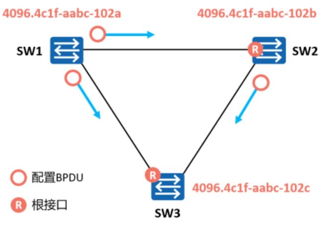
选举指定端口,在每一条链路上选举一个指定的接口
根接口选举出来后,非根桥会使用其在该接口上收到的最优BPDU进行计算,然后将计算得到的配置BPDU与除了根接口之外的其他所有接口所收到的配置BPDU进行比较,一条链路只有一个指定端口。
如果前者更优,则该接口为指定接口,如果后者更优,则该接口为非指定接口。一般情况下,根桥的所有接口都是指定接口

阻塞剩余端口,非指定接口被阻塞
一台交换机上,既不是根接口,又不是指定接口的接口被称为非指定接口。
STP操作的最后一步是阻塞网络中的非指定接口。这一步完成后,网络中的二层环路就此消除。

STP常用配置命令
配置STP模式,缺省为MSTP
stp mode {mstp|stp|rstp}
修改BID优先级,0~61440,步长为4096
stp priority 4096
自动修改优先级,指定主/备根桥,建议指定配置高、性能好的交换机为根桥。
stp root primary/secondary
配置路径开销值的标准
stp pathcost-standard
{ dot1d-1998 | dot1t | legacy }
开销标准
802.1d标准:cost=1~65535
802.1t标准:cost=1~200000000,默认
legacy:cost=1~200000,华为的私有
修改STP端口开销
stp cost 10
修改PID优先级,步长为16
stp port priority 144
显示STP配置信息和参数
display stp [brief]
关闭STP
stp disable
开启STP
stp enable
11、以太网链路聚合实验
手工模式案例
案例需求描述:
SW1、SW2都连接着VLAN10、VLAN20的网络。
SW1和SW1之间通过两根以太网链路互联,为了提供链路冗余以及保证传输可靠性,在SW1、SW1之间配置手工模式的链路聚合。

SW1
sys
sysname SW1
int eth-trunk 1
trunkport gigabitethernet 0/0/1 to 0/0/2
port link-type trunk
port trunk allow-pass vlan 10 20
SW2
sys
sysname SW2
int eth-trunk 1
trunkport gigabitethernet 0/0/1 to 0/0/2
port link-type trunk
port trunk allow-pass vlan 10 20
LACP模式
案例要求:
SW1、SW2都连着VLAN10、VLAN20的网络
SW1和SW2之间通过两根以太网链路互联,为了提供冗余以及保证传输可靠性,在SW1、SW2之间配置LACP模式的链路聚合,并且手动调整优先级让SW1成为主动端,并配置最大活跃端口为2,另外一个链路作为备份。

SW1
sys
sysname SW1
interface eth-trunk 1
mode lacp
max active-linknumber 2
trunkport gig 0/0/1 to 0/0/3
port link-type trunk
port trunk allow-pass vlan 10 20
quit
lacp priority 30000
SW2
sys
sysname SW2
int eth-trunk 1
mode lacp
max active-linknumber 2
trunkport gig 0/0/1 to 0/0/3
port link-type trunk
port trunk allow-pass vlan 10 20
quit
Eth-Trunk常用配置命令
创建聚合端口
interface eth-trunk 1
配置模式
mode manual laod-balance/lacp
配置成员接口
trunkport gigabitethernet 0/0/1 to 0/0/3
配置最小活动链路数量
least active-linknumber 2
配置最大活动链路数量
max active-linknumber 2
开启抢占
lacp preempt enable
配置抢占延迟时间
lacp preempt delay 10
配置负载均衡模式
load-balance 参数
允许不同速率的成员接口
mixed-rate link enable
配置接口
interface gigabitethernet 0/0/1
加入聚合端
eth-trunk 1
配置接口优先级,默认=32768
lacp priority 1
配置系统优先级,默认=32768
lacp priority 1
验证配置信息和状态
display [interface] eth-trunk 1
验证成员信息
display trunkmembership eth-trunk 1
12、DHCP实验
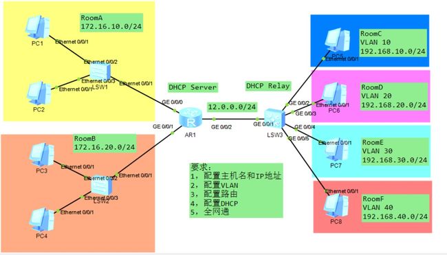
AR1
sys
sysname R1
int g0/0/0
ip add 172.16.10.1 24
int g0/0/1
ip add 172.16.20.1 24
q
dhcp enable
int g0/0/0
dhcp select interface
int g0/0/1
dhcp select interface
int g0/0/2
ip add 12.0.0.1 24
LSW3
sys
sysname LSW3
vlan batch 10 20 30 40
int g0/0/2
port link-type access
port default vlan 10
int g0/0/3
port link-type access
port default vlan 20
int g0/0/4
port link-type access
port default vlan 30
int g0/0/5
port link-type access
port default vlan 40
int vlanif 1
ip add 12.0.0.2 24
int vlanif 10
ip add 192.168.10.1 24
int vlanif 20
ip add 192.168.20.1 24
int vlanif 30
ip add 192.168.30.1 24
int vlanif 40
ip add 192.168.40.1 24
在AR1上配置去LSW3的静态路由,DHCPserver和DHCP服务跨网段所以需要静态路由
ip route-static 192.168.10.1 24 12.0.0.2
ip route-static 192.168.20.1 24 12.0.0.2
ip route-static 192.168.30.1 24 12.0.0.2
ip route-static 192.168.40.1 24 12.0.0.2
配置DHCP中继
创建地址池
AR1
ip pool vlan10
net 192.168.10.0 mask 24
gateway 192.168.10.1

ip pool vlan20
net 192.168.20.0 mask 24
gateway 192.168.20.1

ip pool vlan30
net 192.168.10.0 mask 24
gateway 192.168.30.1

ip pool vlan40
net 192.168.40.0 mask 24
gateway 192.168.40.1

int g0/0/2
dhcp select global
LSW3
dhcp enable
int vlanif 10
dhcp select relay
dhcp relay server-ip 12.0.0.1

int vlanif 20
dhcp select relay
dhcp relay server-ip 12.0.0.1

int vlanif 30
dhcp select relay
dhcp relay server-ip 12.0.0.1

int vlanif 40
dhcp select relay
dhcp relay server-ip 12.0.0.1
配置OSPF
AR1
ospf 1 router-id 1.1.1.1
area 0
net 172.16.10.0 0.0.0.255
net 172.16.20.0 0.0.0.255
net 12.0.0.0 0.0.0.255
LSW3
ospf 1 router-id 3.3.3.3
area 0
net 12.0.0.2
net 192.168.10.0 0.0.0.255
net 192.168.20.0 0.0.0.255
net 192.168.30.0 0.0.0.255
net 192.168.40.0 0.0.0.255
相关查询命令
查看地址池的属性,没有命名就是接口的名字
display ip pool [地址池名称]
查看被使用过的IP地址
display ip pool [地址池的名称] used
13、ACL实验
基本ACL配置
配置需求:在Router上部署基本ACL后,ACL将试图穿越Router的源地址为192.168.1.0/24网段的数据包过滤掉,并放行其他流量,从而禁止192.168.1.0/24网段的用户访问Router右侧的服务器网络。

Router
alc 2000
rule deny source 192.168.1.0 0.0.0.255
rule permit source any
调用ACL
int g0/0/1
traffic-filter inbound acl 2000
quit
高级ACL
某公司通过Router实现各部门之间的互连。为方便管理网络,管理员为公司的研发部和市场部规划了两个网段的IP地址。现要求Router能够限制两个网段之间互访,防止公司机密泄露。

Router
acl 3001
rule deny ip source 10.1.1.0 0.0.0.255 destination 10.1.2.0 0.0.0.255
quit
acl 3002
rule deny ip source 10.1.2.0 0.0.0.255 destination 10.1.2.0 0.0.0.255
quit
调用ACL
int g0/0/1
traffic-filter inbound acl 3001
quit
int g0/0/2
traffic-filter inbound acl 3002
quit
ACL接口调用方向的建议:
基本ACL尽量调用在离目标最近的出站接口
高级ACL尽量调用在离源头最近的入站接口
14、静态NAT实验
静态NAT:一对一地址映射,一个公网地址只保留给一个私网地址使用。
在R1上配置静态NAT将内网主机的私有地址一对一映射到公有地址。

R1
int g0/0/1
nat static enable
nat static global 122.1.2.2 inside 192.168.1.1
nat static global 122.1.2.2 inside 192.168.1.2
nat static global 122.1.2.2 inside 192.168.1.3
相关配置命令
开启NAT静态功能
nat static enable
配置静态NAT
nat static global 公网地址 inside 私网地址
验证静态NAT的配置
display nat static
配置nat static global 公网地址 inside 私网地址时可能出现如下错误提示,出现的原因就是静态NAT是一对一地址映射,一个公网地址只保留给一个私网地址使用。排查一下地址是不是被占用了。
Error: The address conflicts with interface or ARP IP.
15、动态NAT、NAPT、Easy IP配置

R1
nat address-group 1 122.1.2.1 122.1.2.3
acl 2000
rule 5 permit source 192.168.1.0 0.0.0.255
quit
int g0/0/1
动态NAT
nat outbound 2000 address-group 1 no-pat
NAPT
nat outbound 2000 address-group 1
Easy IP
nat outbound 2000
16、NATServer
使用NATServer,让Client1能访问Server

AR1配置命令
sys
sysname R1
int g0/0/0
ip add 192.168.1.254 24
int g0/0/1
ip add 100.100.100.1 24
AR2的配置命令
sys
sysname R2
int g0/0/1
ip add 100.100.100.2 24
int g0/0/0
ip add 200.200.200.2 24
AR1配置
ip route-static 0.0.0.0 0 100.100.100.2
AR1,NATServer
int g0/0/1
nat server protocol tcp global 100.100.100.3 80 inside 192.168.1.1 80
结果验证

17、PAP配置案例
实验要求:
1.在R1与R2之间的PPP链路上启用PAP认证功能;
2.将R1配置为认证方
3.将R2配置为被认证方

R1
sys
sysname R1
aaa
local-user huawei password cipher huawei123
local-user huawei service-type ppp
int s0/0/0
link-protocol ppp
ppp authentication-mode pap
ip add 10.1.1.1 30
R2
sys
sysname R2
int s0/0/0
link-protocol ppp
ppp pap local-user huawei password cipher huawei123
ip add 10.1.1.2 30
18、CHAP配置案例
实验要求:
1.在R1与R2之间的PPP链路上启用CHAP认证功能;
2.将R1配置为认证方
3.将R2配置为被认证方

R1
sys
sysname R1
aaa
local-user huawei password cipher huawei123
local-user huawei service-type ppp
int s0/0/0
link-protocol ppp
ppp authentication-mode chap
ip add 10.1.1.1 30
R2
sys
sysname R2
int s0/0/0
link-protocol ppp
ppp pap local-user huawei password cipher huawei123
ip add 10.1.1.2 30
18、PPPoE案例
PPPoE服务端:
1.在PPPoE服务器端上创建为客户端分配IP的地址池;
2.PPPoE服务器端完成PPPoE客户端认证并分配合法的IP地址。
PPPoE客户端:
1.将R1设置为PPPoE客户端,R2为PPPoE服务器端;
2.在R1上配置PPPoE客户端拨号接口;
3.在R1上配置PPPoE客户端拨号接口的认证功能;
4.R1上的拨号接口获取PPPoE服务器端分配的IP地址;
5.R1通过拨号接口可以访问服务器端。
 R2
R2
1.创建地址池与虚拟模板:
sys
sysname R2
ip pool pool1
network 192.168.1.0 mask 255.255.255.0
gateway-list 192.168.1.254
int virtual-Template 1
ppp authentication-mode chap
ip add 192.168.1.254 255.255.255.0
remote address pool 1
2.将物理接口与虚拟模板绑定
int g0/0/0
pppoe-server bind virtual-template 1
quit
3.创建访问用户
aaa
local-user huawei1 password cipher huawei123
local-user huawei1 service-type ppp
R1
1.创建拨号接口并配置被认证方用户名和密码
sys
sysname R1
dialer-rule
dialer-rule 1 ip permit
quit
int dialer 1
dialer user enterprise@huawei
ppp chap password cipher huawei123
ip address ppp-negotiate
2.将拨号口绑定出接口
int g0/0/1
pppoe-client dial-bundle-number 1
quit
3.配置本端到达服务器的缺省路由
ip route-static 0.0.0.0 0.0.0.0 dialer 1
19、WLAN基础实验
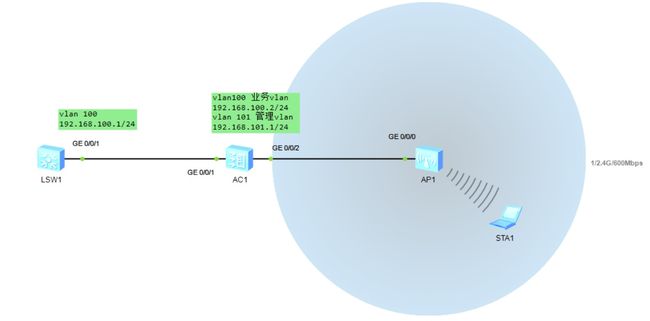
基本配置
sys
vlan batch  100 101

int g0/0/1
port link-type trunk
port trunk allow-pass vlan all
int g0/0/2
port link-type trunk
port  trunk pvid vlan 101
port trunk allow-pass vlan all
quit
配置DHCP
ip pool huawie
net 192.168.100.0 mask 24
gateway-list 192.168.100.254
dns-list 192.168.100.254
quit

dhcp enable
int vlanif 100
ip add 192.168.100.2 255.255.255.0
dhcp select global
int vlanif 101
ip add 192.168.101.1 24
dhcp select interface
创建AP组
capwap source interface vlanif 101
wlan
ap-group name ap
quit
创建域管理模板,并配置AC的国家码
wlan
ap-group name ap
quit
regulatory-domain-profile name domain
country-code CN
quit
ap-group name ap
regulatory-domain-profile name domain
quit
ap auth-mode mac-auth
ap-id 0 ap-mac 00E0-FC57-32B0
ap-name area_1
ap-group ap
yes
配置AC的源接口
capwap source interface vlanif 101
创建名为sec的安全模板,并配置安全策略
security-profile name sec
security wpa2 psk pass-phrase huawei@123 aes
quit
创建名为ssid的SSID模板,并配置SSID的名称是huawei
ssid-profile name ssid
ssid huawei
quit
创建名为vap的VAP模板,配置业务数据转发模式、业务VLAN,并引用安全模板和SSID模板
vap-profile name vap
forward-mode tunnel
service-vlan vlan-id 100
security-profile sec
ssid-profile ssid
quit
配置AP组引用VAP模板,AP上射频0使用vap的配置
ap-group name ap
vap-profile vap wlan 1 radio 0
20、HCIA综合实验
按照拓扑需求搭建实验环境,根据拓扑需求配置相应IP地址,子网掩码为24位

基础配置
R1
sys
sysname R1
int s 4/0/0
ip add 100.1.1.2 24
quit
int loopback1
ip add 1.1.1.1 32
R2
sys
sysname R2
int s 4/0/0
ip add 100.1.1.1 24
int g0/0/0
ip add 23.1.1.2 24
R3
sys
sysname R3
int g0/0/0
ip add 23.1.1.3 24
int g0/0/1
ip add 31.1.1.3 24
LSW1
sys
sysname SW1
vlan batch 10 20
int g0/0/2
port link-type access
port default vlan 10

int g0/0/3
port link-type access
port default vlan 20
LSW2
sys
sysname SW1
vlan batch 10 20
int g0/0/2
port link-type access
port default vlan 10

int g0/0/3
port link-type access
port default vlan 20
可靠性 Eth-trunk配置
SW1
int eth-trunk 1
trunkport g0/0/10 to 0/0/11
port link-type trunk
port trunk allow-pass vlan 10 20
SW2
int eth-trunk 1
trunkport g0/0/10
trunkport g0/0/11
port link-type trunk
port trunk allow-pass vlan 10 20
VLAN间路由
SW1
int vlanif 10
ip add 192.168.1.254 24
int vlanif 20
ip add 192.168.2.254 24
int vlanif 30
ip add 31.1.1.1 24
quit
int g0/0/1
port link-type access
port default vlan 30
路由配置
AR3
ospf 1 router-id 3.3.3.3
area 0
net 31.1.1.3 0.0.0.255
net 23.1.1.3 0.0.0.255
AR2
ip  route-static 0.0.0.0 0 100.1.1.1
ospf 1 router-id 2.2.2.2
import-route static
area 0
net 23.1.1.2 0.0.0.255
SW1
ospf 1 router-id 31.1.1.1
area 0
net 192.168.1.254 0.0.0.255
net 192.168.2.254 0.0.0.255
net 31.1.1.1 0.0.0.255
AR1
ip route-static 0.0.0.0 0 100.1.1.1
DHCP配置
AR3
dhcp enable
ip pool 1
net 192.168.1.0 mask 24
gateway-list 192.168.1.254

ip pool 2
net 192.168.2.0 mask 24
gateway-list 192.168.2.254

int g0/0/1
dhcp select global
DHCP 中继
SW1
dhcp enable
int vlanif10
dhcp select relay
dhcp relay server-ip 31.1.1.3
quit

int vlanif20
dhcp select relay
dhcp relay server-ip 31.1.1.3
quit

int vlanif30
dhcp select relay
dhcp relay server-ip 31.1.1.3
quit
点到点的PPP链路
R2
int s 40/0
ppp authentication-mode chap
quit
aaa
local-user hcip password cipher huawei123
local-user hcip hcip service-type ppp
AR1
int s 4/0/0
ppp chap user hcip
ppp chap password cipher huawei123
quit
NAT
AR2
acl 2001
rule permit source 192.168.1.0 0.0.0.255
rule permit source 192.168.2.0 0.0.0.255
quit
int s4/0/0
nat outbound 2001
附加题
设备管理
在R1上开启Telnet服务,使用用户名密码的验证方式
R1
telnet server enable
aaa
local-user HCIA password cipher huawei
local-user HCIA service-type telnet
local-user HCIA privilege level 5
quit
user-interface vty 0 4
protocol inbound all
authentication-mode aaa
在全网互通的情况下,实现192.168.1.0不能ping 通1.1.1.1,但是可以Telnet 1.1.1.1
acl 3000
rule deny icmp source 192.168.1.0 0.0.0.255 destination 1.1.1.1 0.0.0.0
quit
int g0/0/0
traffic-filter inbound acl 3000