(原创) DE2 实验练习解答—lab 1 (Digital Logic) (DE2) (Quartus II)
Abstract
Switches、Lights and Multiplexers
Release: 1.0
By yf.x
03/12/2010
Introduction
这个练习的目的是学习如何连接简单的输入、输出设备到一个FPGA芯片,并且用这些器件实现一个电路。我们将用DE2开发板上的switches SW17-0作为输入,用LED和7-segment displays作为输出。
完成DE2 实验练习1(Digital Logic)对与初学者来说是一个比较大的实验。我估计,每天要花几小时才能完成。这个实验包括6个部分,主要是组合逻辑电路和使用assign语句。
Part I :第一次使用assign语句
Altera 的DE2开发板有18个拨动开关(toggle switch)和18个红色的LED。Part I非常简单,在实验手册里首先介绍了Verilog的格式,并给出了代码。需要自己做的部分就是把代码粘贴到Quartus II然后运行。当你拨动一个开关(比如Switch 1),对应的LED就会亮(比如LEDR1),这部分在实验手册里解释的很详细。
Part 1代码:
      1

     /*


      2


      3

     (C) yf.x 2010

     http://halflife.cnblogs.com/


      4


      5

     Filename : part1.v


      6


      7

     Compiler : Quartus II 9.1 Web Edition


      8


      9

     Description : Demo how to use Switch and led


     10


     11

     Release : 03/05/2010 1.0


     12


     13


     */


     14


     15


     //

     Simple module that conects the SW switchs to the LEDR lights


     16


     17


     module

      part1(SW,LEDR);


     18


     19


     input

      [

     17

     :

     0

     ] SW;

     //

     toggle switches


     20


     21


     output

      [

     17

     :

     0

     ] LEDR;

     //

     red leds


     22


     23


     assign

      LEDR

     =

     SW;


     24


     25


     endmodule
Part II:设计一个8位的2选1多路选择器
用Verilog设计一个多路选择器有很多种方法。但是在这个实验里,要求只能用门级电路描述。比如:assign m=(~s&x)|(s&y);这里x和y是输入,s是选择信号,m是输出。X被定义为SW 0到7,Y被定义为SW 8到15,S被定义为SW17,M被定义为绿色的LEDG 0到7.这部分的完整代码如下。
Part II 代码:
      1

     /*


      2


      3

     (C) yf.x 2010

     http://halflife.cnblogs.com/


      4


      5

     Filename : part2.v


      6


      7

     Compiler : Quartus II 9.1 Web Edition


      8


      9

     Description : Demo how to use assign statements


     10


     11

     Release : 03/05/2010 1.0


     12


     13


     */


     14


     15


     //

     Top level file of part2


     16


     17


     module

      part2(LEDR,LEDG,SW);


     18


     19


     input

      [

     17

     :

     0

     ]SW;


     20


     21


     output

      [

     17

     :

     0

     ]LEDR;


     22


     23


     output

      [

     7

     :

     0

     ]LEDG;


     24


     25


     wire

      s;


     26


     27


     wire

      [

     7

     :

     0

     ]X,Y,M;


     28


     29


     assign

      S

     =

     SW[

     17

     ];


     30


     31


     assign

      X

     =

     SW[

     7

     :

     0

     ];


     32


     33


     assign

      Y

     =

     SW[

     15

     :

     8

     ];


     34


     35


     assign

      LEDR

     =

     SW;


     36


     37


     assign

      LEDG

     =

     M;


     38


     39

      mux2to1 m7(S,X[

     7

     ],Y[

     7

     ],M[

     7

     ]);


     40


     41

      mux2to1 m6(S,X[

     6

     ],Y[

     6

     ],M[

     6

     ]);


     42


     43

      mux2to1 m5(S,X[

     5

     ],Y[

     5

     ],M[

     5

     ]);


     44


     45

      mux2to1 m4(S,X[

     4

     ],Y[

     4

     ],M[

     4

     ]);


     46


     47

      mux2to1 m3(S,X[

     3

     ],Y[

     3

     ],M[

     3

     ]);


     48


     49

      mux2to1 m2(S,X[

     2

     ],Y[

     2

     ],M[

     2

     ]);


     50


     51

      mux2to1 m1(S,X[

     1

     ],Y[

     1

     ],M[

     1

     ]);


     52


     53

      mux2to1 m0(S,X[

     0

     ],Y[

     0

     ],M[

     0

     ]);


     54


     55


     endmodule


     56


     57


     //

     1-bit 2-to1 multiplexer


     58


     59


     module

      mux2to1(s,x,y,m);


     60


     61


     input

      s,x,y;


     62


     63


     output

      m;


     64


     65


     assign

      m

     =

     (

     ~

     s

     &

     x)

     |

     (s

     &

     y);


     66


     67


     endmodule


     68


     69
在我的代码里,有一个小技巧。我把RTL代码分成2部分。1个主模块和1个多路选择器模块。通过调用多选器模块,可以很容易的实现设计。(这里因为用到很多引脚,为了方便引脚分配,输入、输出端口名和板上的器件名相同。)
Part III:设计一个3位的5选一多路选择器
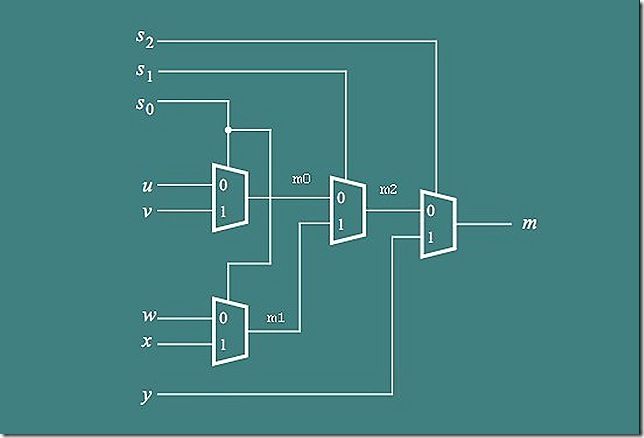
设计一个3位的5选1多路选择器很简单。如图1所示,使用了4个3位的2选1的多路选择器。完整代码如下:
图 1 5选1多路选择器
Part III 代码:
      1

     /*


      2


      3

     (C) yf.x 2010

     http://halflife.cnblogs.com/


      4


      5

     Filename : part3.v


      6


      7

     Compiler : Quartus II 9.1 Web Edition


      8


      9

     Description : Demo how to use assign statements


     10


     11

     Release : 03/05/2010 1.0


     12


     13


     */


     14


     15


     //

     3BIT 5 to 1 Multiplexer Module


     16


     17


     module

      mux_3bit_5to1(S,U,V,W,X,Y,M);


     18


     19


     input

     [

     2

     :

     0

     ]S,U,V,W,X,Y;


     20


     21


     output

     [

     2

     :

     0

     ]M;


     22


     23


     wire

     [

     2

     :

     0

     ]m0,m1,m2;


     24


     25


     //

      Leftmost 2 to 1 Multiplexers


     26


     27


     //

     Top


     28


     29


     assign

      m0[

     0

     ]

     =

      (

     ~

     S[

     0

     ]

     &

     U[

     0

     ])

     |

     (S[

     0

     ]

     &

     V[

     0

     ]);


     30


     31


     assign

      m0[

     1

     ]

     =

      (

     ~

     S[

     0

     ]

     &

     U[

     1

     ])

     |

     (S[

     0

     ]

     &

     V[

     1

     ]);


     32


     33


     assign

      m0[

     2

     ]

     =

      (

     ~

     S[

     0

     ]

     &

     U[

     2

     ])

     |

     (S[

     0

     ]

     &

     V[

     2

     ]);


     34


     35


     //

     Bottom


     36


     37


     assign

      m1[

     0

     ]

     =

      (

     ~

     S[

     0

     ]

     &

     W[

     0

     ])

     |

     (S[

     0

     ]

     &

     X[

     0

     ]);


     38


     39


     assign

      m1[

     1

     ]

     =

      (

     ~

     S[

     0

     ]

     &

     W[

     1

     ])

     |

     (S[

     0

     ]

     &

     X[

     1

     ]);


     40


     41


     assign

      m1[

     2

     ]

     =

      (

     ~

     S[

     0

     ]

     &

     W[

     2

     ])

     |

     (S[

     0

     ]

     &

     X[

     2

     ]);


     42


     43


     //

     Middle Multiplexer


     44


     45


     assign

      m2[

     0

     ]

     =

      (

     ~

     S[

     1

     ]

     &

     m0[

     0

     ])

     |

     (S[

     1

     ]

     &

     m1[

     0

     ]);


     46


     47


     assign

      m2[

     1

     ]

     =

      (

     ~

     S[

     1

     ]

     &

     m0[

     1

     ])

     |

     (S[

     1

     ]

     &

     m1[

     1

     ]);


     48


     49


     assign

      m2[

     2

     ]

     =

      (

     ~

     S[

     1

     ]

     &

     m0[

     2

     ])

     |

     (S[

     1

     ]

     &

     m1[

     2

     ]);


     50


     51


     //

     Last Multiplexer


     52


     53


     assign

      M[

     0

     ]

     =

      (

     ~

     S[

     2

     ]

     &

     m2[

     0

     ])

     |

     (S[

     2

     ]

     &

     Y[

     0

     ]);


     54


     55


     assign

      M[

     1

     ]

     =

      (

     ~

     S[

     2

     ]

     &

     m2[

     1

     ])

     |

     (S[

     2

     ]

     &

     Y[

     1

     ]);


     56


     57


     assign

      M[

     2

     ]

     =

      (

     ~

     S[

     2

     ]

     &

     m2[

     2

     ])

     |

     (S[

     2

     ]

     &

     Y[

     2

     ]);


     58


     59


     endmodule


     60


     61
part IV:设计一个7segment 显示“HELLO”
这部分要求用一个7segment显示H、E、L、O。需要注意DE2上的七段码数码管是共阴极,对应的真值表见表 1 7-segment 译码真值表:
| c2c1c0 |
character |
7_segment |
| 000 |
H |
1001000 |
| 001 |
E |
0110000 |
| 010 |
L |
1110001 |
| 011 |
O |
0000001 |
| 100 |
blank |
1111111 |
| 101 |
||
| 110 |
||
| 111 |
表 1 7-segment 译码真值表
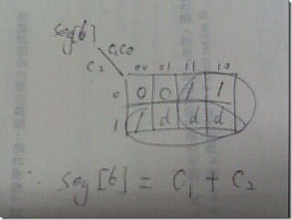
表达式化简,用卡诺图,比如seg[6](上表7-segment的最右边的一列),化简过程如下图所示:
Part IV:代码
      1

     /*


      2


      3

     (C) yf.x 2010

     http://halflife.cnblogs.com/


      4


      5

     Filename : part4.v


      6


      7

     Compiler : Quartus II 9.1 Web Edition


      8


      9

     Description : Demo how to use 7segment display


     10


     11

     Release : 03/12/2010 1.0


     12


     13


     */


     14


     15


     //

     use a 7segment display H、E、L、O


     16


     17


     module

      part4(SW,LEDR,HEX0);


     18


     19


     input

      [

     2

     :

     0

     ] SW;


     20


     21


     output

      [

     2

     :

     0

     ] LEDR;


     22


     23


     output

      [

     0

     :

     6

     ] HEX0;


     24


     25


     assign

      LEDR

     =

     SW;


     26


     27


     //

     Seven Segment Decoder for "HELO"


     28


     29


     assign

      HEX0[

     0

     ]

     =

      SW[

     2

     ]

     |~

     SW[

     0

     ];


     30


     31

      assign HEX0[1]=SW[2]|(SW[1]&~SW[0])|(~SW[1]&SW[0]);


     32


     33


      assign HEX0[2]=SW[2]|(SW[1]&~SW[0])|(~SW[1]&SW[0])

     ;


     34


     35


     assign

      HEX0[

     3

     ]

     =

      SW[

     2

     ]

     |

     (

     ~

     SW[

     1

     ]

     &~

     SW[

     0

     ]);


     36


     37


     assign

      HEX0[

     4

     ]

     =

      SW[

     2

     ];


     38


     39


     assign

      HEX0[

     5

     ]

     =

      SW[

     2

     ];


     40


     41


     assign

      HEX0[

     6

     ]

     =

      SW[

     2

     ]

     |

     SW[

     1

     ];


     42


     43


     endmodule


     44


     45
注:因为要求用连续赋值语句和布尔逻辑实现,对于七段码的每一段的表达式都可以根据真值表先化简(当然综合工具会自动化简,但是如果考综合工具化简,每个表达式就会很长)。化简就会用到我们学过的卡诺图图(以前一直觉得卡诺图用不上L)。
Part V:用5个7segment循环显示HELLO
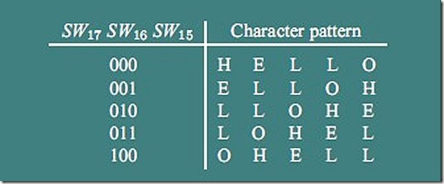
这部分要求用5个数码管循环显示HELLO,涉及part III和part IV的引用。5个数码管循环显示如图2.
图 2 数码管循环显示HELLO
Part V 代码:
      1

     /*


      2


      3

     (C) yf.x 2010

     http://halflife.cnblogs.com/


      4


      5

     Filename : part5.v


      6


      7

     Compiler : Quartus II 9.1 Web Edition


      8


      9

     Description : Demo how to rotating display


      10


      11

     Release : 03/12/2010 1.0


      12


      13


     */


      14


      15


     //

     Top level file


      16


      17


     module

      part5(SW,HEX4,HEX3,HEX2,HEX1,HEX0);


      18


      19


     input

      [

     17

     :

     0

     ]SW;


      20


      21


     output

      [

     0

     :

     6

     ] HEX4,HEX3,HEX2,HEX1,HEX0;


      22


      23


     wire

      [

     2

     :

     0

     ] M4,M3,M2,M1,M0;


      24


      25

      mux_3bit_5to1 N4(SW[

     17

     :

     15

     ],SW[

     14

     :

     12

     ],SW[

     11

     :

     9

     ],


      26


      27

     SW[

     8

     :

     6

     ],SW[

     5

     :

     3

     ],SW[

     2

     :

     0

     ],M4);


      28


      29

      mux_3bit_5to1 N3(SW[

     17

     :

     15

     ],SW[

     11

     :

     9

     ],SW[

     8

     :

     6

     ],


      30


      31

     SW[

     5

     :

     3

     ],SW[

     2

     :

     0

     ],SW[

     14

     :

     12

     ],M3);


      32


      33

      mux_3bit_5to1 N2(SW[

     17

     :

     15

     ],SW[

     8

     :

     6

     ],SW[

     5

     :

     3

     ],


      34


      35

     SW[

     2

     :

     0

     ],SW[

     14

     :

     12

     ],SW[

     11

     :

     9

     ],M2);


      36


      37

      mux_3bit_5to1 N1(SW[

     17

     :

     15

     ],SW[

     5

     :

     3

     ],SW[

     2

     :

     0

     ],


      38


      39

     SW[

     14

     :

     12

     ],SW[

     11

     :

     9

     ],SW[

     8

     :

     6

     ],M1);


      40


      41

      mux_3bit_5to1 N0(SW[

     17

     :

     15

     ],SW[

     2

     :

     0

     ],SW[

     14

     :

     12

     ],


      42


      43

     SW[

     11

     :

     9

     ],SW[

     8

     :

     6

     ],SW[

     5

     :

     3

     ],M0);


      44


      45

      char_7seg H4(M4,HEX4);


      46


      47

      char_7seg H3(M3,HEX3);


      48


      49

      char_7seg H2(M2,HEX2);


      50


      51

      char_7seg H1(M1,HEX1);


      52


      53

      char_7seg H0(M0,HEX0);


      54


      55


     endmodule


      56


      57


     //

     implements a 7_segment decoder for H,E,L,O,and blank


      58


      59

     module

      char_7seg(c,display);


      60


      61


     input

      [

     2

     :

     0

     ]c;


      62


      63


     output

      [

     0

     :

     6

     ]display;


      64


      65

     //

     Seven Segment Decoder for "HELO"


      66


      67


     assign

      display[

     0

     ]

     =

      c[

     2

     ]

     |~

     c[

     0

     ];


      68


      69


     assign

      display[

     1

     ]

     =

      c[

     2

     ]

     |

     (c[

     0

     ]

     &~

     c[

     1

     ])

     |

     (c[

     1

     ]

     &~

     c[

     2

     ]

     &~

     c[

     0

     ]);


      70


      71


     assign

      display[

     2

     ]

     =

      c[

     2

     ]

     |

     (c[

     0

     ]

     &~

     c[

     1

     ])

     |

     (

     ~

     c[

     0

     ]

     &

     c[

     1

     ]

     &~

     c[

     2

     ]);


      72


      73


     assign

      display[

     3

     ]

     =

      c[

     2

     ]

     |

     (

     ~

     c[

     1

     ]

     &~

     c[

     0

     ]);


      74


      75


     assign

      display[

     4

     ]

     =

      c[

     2

     ];


      76


      77


     assign

      display[

     5

     ]

     =

      c[

     2

     ];


      78


      79


     assign

      display[

     6

     ]

     =

      c[

     2

     ]

     |

     c[

     1

     ];


      80


      81

     endmodule


      82


      83

     //

     3BIT 5 to 1 Multiplexer Module


      84


      85

     module

      mux_3bit_5to1(S,U,V,W,X,Y,M);


      86


      87


     input

     [

     2

     :

     0

     ]S,U,V,W,X,Y;


      88


      89


     output

     [

     2

     :

     0

     ]M;


      90


      91


     wire

     [

     2

     :

     0

     ]m0,m1,m2;


      92


      93

     //

      Leftmost 2 to 1 Multiplexers


      94


      95

     //

     Top


      96


      97


     assign

      m0[

     0

     ]

     =

      (

     ~

     S[

     0

     ]

     &

     U[

     0

     ])

     |

     (S[

     0

     ]

     &

     V[

     0

     ]);


      98


      99


     assign

      m0[

     1

     ]

     =

      (

     ~

     S[

     0

     ]

     &

     U[

     1

     ])

     |

     (S[

     0

     ]

     &

     V[

     1

     ]);


     100


     101


     assign

      m0[

     2

     ]

     =

      (

     ~

     S[

     0

     ]

     &

     U[

     2

     ])

     |

     (S[

     0

     ]

     &

     V[

     2

     ]);


     102


     103

     //

     Bottom


     104


     105


     assign

      m1[

     0

     ]

     =

      (

     ~

     S[

     0

     ]

     &

     W[

     0

     ])

     |

     (S[

     0

     ]

     &

     X[

     0

     ]);


     106


     107


     assign

      m1[

     1

     ]

     =

      (

     ~

     S[

     0

     ]

     &

     W[

     1

     ])

     |

     (S[

     0

     ]

     &

     X[

     1

     ]);


     108


     109


     assign

      m1[

     2

     ]

     =

      (

     ~

     S[

     0

     ]

     &

     W[

     2

     ])

     |

     (S[

     0

     ]

     &

     X[

     2

     ]);


     110


     111

     //

     Middle Multiplexer


     112


     113


     assign

      m2[

     0

     ]

     =

      (

     ~

     S[

     1

     ]

     &

     m0[

     0

     ])

     |

     (S[

     1

     ]

     &

     m1[

     0

     ]);


     114


     115


     assign

      m2[

     1

     ]

     =

      (

     ~

     S[

     1

     ]

     &

     m0[

     1

     ])

     |

     (S[

     1

     ]

     &

     m1[

     1

     ]);


     116


     117


     assign

      m2[

     2

     ]

     =

      (

     ~

     S[

     1

     ]

     &

     m0[

     2

     ])

     |

     (S[

     1

     ]

     &

     m1[

     2

     ]);


     118


     119

     //

     Last Multiplexer


     120


     121


     assign

      M[

     0

     ]

     =

      (

     ~

     S[

     2

     ]

     &

     m2[

     0

     ])

     |

     (S[

     2

     ]

     &

     Y[

     0

     ]);


     122


     123


     assign

      M[

     1

     ]

     =

      (

     ~

     S[

     2

     ]

     &

     m2[

     1

     ])

     |

     (S[

     2

     ]

     &

     Y[

     1

     ]);


     124


     125


     assign

      M[

     2

     ]

     =

      (

     ~

     S[

     2

     ]

     &

     m2[

     2

     ])

     |

     (S[

     2

     ]

     &

     Y[

     2

     ]);


     126


     127

     endmodule


     128


     129
技巧:同样的选择参数被用于不同的多路选择器实例引用,不同的多路选择器连接不同的数码管,每个数码管都可以循环显示不同的字符。前两部分的代码稍稍修改就可直接引用。
Part VI:用8个数码管循环显示HELLO
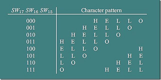
要求按照图 3 数码管循环显示,这是整个实验最复杂的部分,需要用到前5部分的信息。因为要用到选择信号的8中状态,需要创建一个8选1的多路选择器。其余就类似第5部分。注意在实例引用8选1多路器时8个输入信号的排列(我的神啊,眼睛差点都看花了J)!!
图 3 数码管循环显示
Part VI 代码:
1
/*
2
3
(C) yf.x 2010
http://halflife.cnblogs.com/
4
5
Filename : part6.v
6
7
Compiler : Quartus II 9.1 Web Edition
8
9
Description : Demo how to use 8 7seg rotating display
10
11
Release : 03/12/2010 1.0
12
13
*/
14
15
//
Top level file
16
17
module
part6(SW,HEX7,HEX6,HEX5,HEX4,HEX3,HEX2,
18
19
HEX1,HEX0);
20
21
input
[
17
:
0
]SW;
22
23
output
[
0
:
6
]HEX7,HEX6,HEX5,HEX4,HEX3,HEX2,
24
HEX1,HEX0;
25
26
wire
[
2
:
0
]M7,M6,M5,M4,M3,M2,M1,M0;
27
28
mux_3bit_8to1 N7(SW[
17
:
15
],SW[
2
:
0
],SW[
2
:
0
],SW[
2
:
0
], SW[
14
:
12
],SW[
11
:
9
],SW[
8
:
6
],SW[
8
:
6
],SW[
5
:
3
],M7);
29
30
mux_3bit_8to1 N6(SW[
17
:
15
],SW[
2
:
0
],SW[
2
:
0
],SW[
14
:
12
], SW[
11
:
9
],SW[
8
:
6
],SW[
8
:
6
],SW[
5
:
3
],SW[
2
:
0
],M6);
31
32
mux_3bit_8to1 N5(SW[
17
:
15
],SW[
2
:
0
],SW[
14
:
12
],
33
SW[
11
:
9
],SW[
8
:
6
],SW[
8
:
6
],SW[
5
:
3
],SW[
2
:
0
],SW[
2
:
0
],M5);
34
35
mux_3bit_8to1 N4(SW[
17
:
15
],SW[
14
:
12
],SW[
11
:
9
],
36
SW[
8
:
6
],SW[
8
:
6
],SW[
5
:
3
],SW[
2
:
0
],SW[
2
:
0
],SW[
2
:
0
],M4);
37
38
mux_3bit_8to1 N3(SW[
17
:
15
],SW[
11
:
9
],SW[
8
:
6
],SW[
8
:
6
], SW[
5
:
3
],SW[
2
:
0
],SW[
2
:
0
],SW[
2
:
0
],SW[
14
:
12
],M3);
39
40
mux_3bit_8to1 N2(SW[
17
:
15
],SW[
8
:
6
],SW[
8
:
6
],SW[
5
:
3
], SW[
2
:
0
],SW[
2
:
0
],SW[
2
:
0
],SW[
14
:
12
],SW[
11
:
9
],M2);
41
42
mux_3bit_8to1 N1(SW[
17
:
15
],SW[
8
:
6
],SW[
5
:
3
],
43
SW[
2
:
0
],SW[
2
:
0
],SW[
2
:
0
],SW[
14
:
12
],SW[
11
:
9
],SW[
8
:
6
],M1);
44
45
mux_3bit_8to1 N0(SW[
17
:
15
],SW[
5
:
3
],SW[
2
:
0
],SW [
2
:
0
], SW[
2
:
0
],SW[
14
:
12
],SW[
11
:
9
],SW[
8
:
6
],SW[
8
:
6
],M0);
46
47
char_7seg H7(M7,HEX7);
48
49
char_7seg H6(M6,HEX6);
50
51
char_7seg H5(M5,HEX5);
52
53
char_7seg H4(M4,HEX4);
54
55
char_7seg H3(M3,HEX3);
56
57
char_7seg H2(M2,HEX2);
58
59
char_7seg H1(M1,HEX1);
60
61
char_7seg H0(M0,HEX0);
62
63
endmodule
64
65
//
3bit 8to1 multiplexer
66
67
//
use 7 3bit 2-to-1 multiplexer
68
69
module
mux_3bit_8to1(S,U,V,W,X,Y,Z,A,B,M);
70
71
input
[
2
:
0
]S,U,V,W,X,Y,Z,A,B;
72
73
output
[
2
:
0
]M;
74
75
wire
[
2
:
0
]n0,n1,n2,n3,n4,n5;
76
77
//
2 to 1 Multiplexers
78
79
//
one
80
81
assign
n0[
0
]
=
(
~
S[
0
]
&
U[
0
])
|
(S[
0
]
&
V[
0
]);
82
83
assign
n0[
1
]
=
(
~
S[
0
]
&
U[
1
])
|
(S[
0
]
&
V[
1
]);
84
85
assign
n0[
2
]
=
(
~
S[
0
]
&
U[
2
])
|
(S[
0
]
&
V[
2
]);
86
87
//
two
88
89
assign
n1[
0
]
=
(
~
S[
0
]
&
W[
0
])
|
(S[
0
]
&
X[
0
]);
90
91
assign
n1[
1
]
=
(
~
S[
0
]
&
W[
1
])
|
(S[
0
]
&
X[
1
]);
92
93
assign
n1[
2
]
=
(
~
S[
0
]
&
W[
2
])
|
(S[
0
]
&
X[
2
]);
94
95
//
three
96
97
assign
n2[
0
]
=
(
~
S[
0
]
&
Y[
0
])
|
(S[
0
]
&
Z[
0
]);
98
99
assign
n2[
1
]
=
(
~
S[
0
]
&
Y[
1
])
|
(S[
0
]
&
Z[
1
]);
100
101
assign
n2[
2
]
=
(
~
S[
0
]
&
Y[
2
])
|
(S[
0
]
&
Z[
2
]);
102
103
//
four
104
105
assign
n3[
0
]
=
(
~
S[
0
]
&
A[
0
])
|
(S[
0
]
&
B[
0
]);
106
107
assign
n3[
1
]
=
(
~
S[
0
]
&
A[
1
])
|
(S[
0
]
&
B[
1
]);
108
109
assign
n3[
2
]
=
(
~
S[
0
]
&
A[
2
])
|
(S[
0
]
&
B[
2
]);
110
111
//
five
112
113
assign
n4[
0
]
=
(
~
S[
1
]
&
n0[
0
])
|
(S[
1
]
&
n1[
0
]);
114
115
assign
n4[
1
]
=
(
~
S[
1
]
&
n0[
1
])
|
(S[
1
]
&
n1[
1
]);
116
117
assign
n4[
2
]
=
(
~
S[
1
]
&
n0[
2
])
|
(S[
1
]
&
n1[
2
]);
118
119
//
six
120
121
assign
n5[
0
]
=
(
~
S[
1
]
&
n2[
0
])
|
(S[
1
]
&
n3[
0
]);
122
123
assign
n5[
1
]
=
(
~
S[
1
]
&
n2[
1
])
|
(S[
1
]
&
n3[
1
]);
124
125
assign
n5[
2
]
=
(
~
S[
1
]
&
n2[
2
])
|
(S[
1
]
&
n3[
2
]);
126
127
//
seven
128
129
assign
M[
0
]
=
(
~
S[
2
]
&
n4[
0
])
|
(S[
2
]
&
n5[
0
]);
130
131
assign
M[
1
]
=
(
~
S[
2
]
&
n4[
1
])
|
(S[
2
]
&
n5[
1
]);
132
133
assign
M[
2
]
=
(
~
S[
2
]
&
n4[
2
])
|
(S[
2
]
&
n5[
2
]);
134
135
endmodule
136
137
//
implements a 7_segment decoder for H,E,L,O,and blank
138
139
module
char_7seg(c,display);
140
141
input
[
2
:
0
]c;
142
143
output
[
0
:
6
]display;
144
145
//
Seven Segment Decoder for "HELO"
146
147
assign
display[
0
]
=
c[
2
]
|~
c[
0
];
148
149
assign
display[
1
]
=
c[
2
]
|
(c[
0
]
&~
c[
1
])
|
(c[
1
]
&~
c[
2
]
&~
c[
0
]);
150
151
assign
display[
2
]
=
c[
2
]
|
(c[
0
]
&~
c[
1
])
|
(
~
c[
0
]
&
c[
1
]
&~
c[
2
]);
152
153
assign
display[
3
]
=
c[
2
]
|
(
~
c[
1
]
&~
c[
0
]);
154
155
assign
display[
4
]
=
c[
2
];
156
157
assign
display[
5
]
=
c[
2
];
158
159
assign
display[
6
]
=
c[
2
]
|
c[
1
];
160
161
endmodule
162
163
注:3位8选1多路器的设计思想如同前面的3位5选1多路器的设计思想一致。在这部分,我预选设置SW的值如表2。
| SW |
预设值 |
数码管显示 |
| SW14-12 |
000 |
H |
| SW11-9 |
001 |
E |
| SW8-6 |
010 |
L |
| SW5-3 |
011 |
O |
| SW2-0 |
100 |
blank |
Conclusion
整体来看,Altera的实验设计很花心思。在实验1,主要要求用基本的布尔逻辑实现。不允许用高级的RTL描述,考查门级电路实现(心中有电路图,描述就不难。J)。完成整个实验非常有趣,积累基本经验,并且回顾和更好的理解底层的数字逻辑设计。
See Also
Altera’s website: www.Altera.com


