- Zabbix 企业级分布式监控部署
伤不起bb
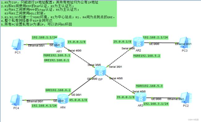
zabbix分布式
目录一、监控系统基础认知1.为什么需要监控?2.监控的5个层次(从底层到上层)3.监控系统的基本原理二、Zabbix系统详解1.Zabbix是什么?2.Zabbix核心功能3.Zabbix核心组件三、Zabbix部署实战(分布式架构)1.环境准备(4台服务器)2.部署ZabbixServer(核心步骤)步骤1:添加Zabbix源并安装依赖步骤2:配置数据库步骤3:导入Zabbix初始数据步骤4:配
- Unity VR多人手术系统恢复3:Agora语音通讯系统问题解决全记录
马特说
unityvr游戏引擎
前言这是一个Unity多人VR手术模拟项目,已经搁置了近两年时间。最近重新启动了这个项目,然而在恢复过程中却遇到了些的技术障碍。项目重启遇到的挑战当我们重新部署和测试系统时,发现原本运行良好的Agora语音通讯功能完全失效了。经过初步排查发现了以下问题:外部服务依赖失效-两年前依赖的第三方Token服务器已经宕机代码架构问题暴露-多个组件重复获取Token,产生混乱的调用逻辑配置不一致-频道命名规
- Javaweb笔记
笙鹿鸣
html前端html5
HTMLHTML网页常用基础知识网页结构JavaSEC/SClientserver客户端–服务器JavaWebB/SBroswerServer浏览器–服务器网页的组成部分:内容(结构)、表现、行为HTML:HyperTextMarkupLanguage(超文本标记语言)ALT+F2选择浏览器HTML书写规范:表示整个html页面的开始头信息标题标题body是页面的主体内容页面主体内容表示整个htm
- https交互原理
黑塞123
Modernc++https网络协议
Https交互时序图:HTTPS通信中结合RSA和AES加密的流程,本质是利用RSA的安全特性交换AES密钥,再用高效的AES加密实际数据传输。HTTPS交互核心流程(TLS/SSL握手)1.建立TCP连接客户端通过TCP三次握手连接服务器的443端口。2.TLS/SSL握手(密钥协商阶段)ClientHello客户端发送支持的功能列表:TLS版本、支持的加密套件(如TLS_RSA_WITH_AE
- 微信扫描登录详解
introverter
微信扫描java后台接口微信扫描登录
微信扫描登录第一步:准备工作在application.properties添加相关配置信息微信开放平台appidwx.open.app_id=你的appid微信开放平台appsecretwx.open.app_secret=你的appsecret微信开放平台重定向urlwx.open.redirect_url=http://你的服务器名称/api/ucenter/wx/callback创建util
- 微信二维码扫描登录流程详解
黑塞123
QT二维码登录流程
二维码扫描登录流程细节(项目经验)1:获取二维码信息PC会优先存放服务器生成的唯一密钥:比如source、secret以密文形式存储大致发送字段:sourcesecretmac(mac地址)服务器生成二维码信息:二维码字符、二维码过期时间、二维码状态。并将mac与二维码信息绑定后2:获取二维码状态、校验二维码是否过期客户端解析二维码信息生成二维码开启定时器1:轮询检测二维码过期时间(二维码过期暂停
- 2021-10-26
弗莱斯曼
凡事预则立,不预则废。记忆力以及理解能力,需要不断的用事情去打磨,越磨越灵光,越刺激越好用。不是在总结,就是在总结的路上。闲言碎语跟进给湖北区域客户做实施同事的行程,客户原定25号开始给服务器上架,具体负责这块的区域实施负责人安排同事于27号上门服务。跟内部同事沟通NeonSAN软件是否具备升级条件的必要性,跟实施负责人约时间共同探讨这个事情,会议上由于研发侧负责人具体不了解前因后果,给的论断不具
- 远程连接之ssh的使用(日志监控)
小朱撕码迹
ssh远程连接linuxubuntuwindows
ssh的简介ssh服务【SecureShell】:SSH为建立在应用层基础上的安全协议。SSH是较可靠,专为远程登录提供服务。解决的问题:对服务器的远程控制,远程操作。ssh服务是安全的、加密、基于S/C(服务端/客户端)的远程连接服务【运行的sshd进程会监听22号端口,提供远程登录的服务,服务的内容:远程操作服务器】OpenSSH是使用SSH协议远程登录的首选连接工具。它对所有流量进行加密,以
- Linux通过 SSH 使用 rsync 进行文件传输
赛男丨木子丿小喵
运维linuxssh运维
目录目的整体思路ssh建立连接A服务器上的操作输入ssh-keygen生成密钥对查看公钥B服务器上的操作设置公钥认证A服务器上的操作使用SSH登录进行测试同步数据知识拓展SSH(SecureShell)rsync(RemoteSync)目的使用SSH(SecureShell)建立两台Linux服务器之间的连接,并使用rsync(RemoteSync)来同步文件,假设A服务器想同步数据到B服务器整体
- 大模型——TRAE+Milvus MCP 自然语言就能搞定向量数据库
不二人生
大模型milvus数据库trae大模型
大模型——TRAE+MilvusMCP自然语言就能搞定向量数据库不久前,继Cursor和ClaudeDesktop在海外市场掀起智能编程浪潮后,字节跳动TRAE海外版也进入了付费模式。相较前两款海外产品,TRAE集成了代码补全、智能问答和Agent模式之外,还可以为中文开发者带来本土化的智能编程体验。恰逢其时,MilvusMCP服务器新增了SSE(Server-SentEvents)支持。相比传统
- 集群技术笔记-HAProxy 与 Keepalived 高可用负载均衡实战
目录前言HAProxy一、HAProxy介绍(一)定义(二)核心优势(三)调度算法速查表(四)工作模式(五)配置文件结构(六)健康检查字段二、搭建负载均衡集群(一)准备基本环境(二)配置流程配置真实服务器配置代理服务器(三)客户端验证三、配置健康检查页面(一)修改配置文件追加配置内容(二)重启服务(三)浏览器访问验证Keepalived一、Keepalived介绍(一)定义(二)功能(三)工作原理
- LVS调度算法
等风来也chen
随笔lvslvs调度算法
LVS的十种调度算法一)静态调度:①RR(RoundRobin):轮询调度轮询调度算法的原理是每一次把来自用户的请求轮流分配给内部中的服务器,从1开始,直到N(内部服务器个数),然后重新开始循环。算法的优点是其简洁性,它无需记录当前所有连接的状态,所以它是一种无状态调度。【提示:这里是不考虑每台服务器的处理能力】②WRR:weight,加权轮询(以权重之间的比例实现在各主机之间进行调度)由于每台服
- 【华为419机考真题】服务器能耗统计,JAVA 题解
梦想橡皮擦
华为服务器java华为OD机试华为OD
最近更新的博客华为od2023|什么是华为od,od薪资待遇,od机试题清单华为OD机试真题大全,用Python解华为机试题|机试宝典【华为OD机试】全流程解析+经验分享,题型分享,防作弊指南华为od机试,独家整理已参加机试人员的实战技巧本篇题解:服务器耗能题目描述服务器有三种运行状态:空载,单任务,多任务,每个时间片的能耗的分别为111、333、444,每个任务由起始时间片和结束时间片定义运行时
- LVS的10种调度算法
蜡笔晓心
其他
1.1静态算法:1.1.1rr(roundrobin):轮询调度算法:轮询调度算法的原理就是依次将用户的访问请求,平均的分配到每一台web服务节点上,从1开始,到最后一台服务器节点结束,然后在开始新一轮的循环,这种算法简单,但是没有考虑到每台节点服务器的具体性能1.1.2wrr(weight):权重调度算法由于每台服务器的性能会高低不同,wrr将会根据管理员设定的权重值来分配访问请求,权重值越大的
- lvs调度算法(10种)
beyoundout
lvs算法
一、静态算法(不考虑后端真实服务器的负载情况,按算法该谁就分配给谁)1.rr(RoundRobin)轮询算法算法原理:将外部请求按顺序轮流分配到集群中的真实服务器上,它均等地对待每一台服务器,而不管服务器上实际的连接数和系统负载举例:就像在食堂打饭,有三个打饭窗口。学生们排成一队从餐厅门口进入食堂,依次到第一个窗口、第二个窗口、第三个窗口打饭,后面的学生再从第一个窗口循环,每个窗口平等地接待学生,
- 华为服务器管理工具(Intelligent Platform Management Interface)
小小玫瑰大智慧
华为服务器运维
一、核心功能与技术架构硬件级监控与控制全维度传感器管理:实时监测CPU、内存、硬盘、风扇、电源等硬件组件的温度、电压、转速等参数,支持超过200种传感器类型。例如,通过IPMI命令ipmitoolsdrelist可快速获取服务器传感器状态,并通过正则表达式提取关键指标。远程操作能力:支持远程开关机、重启、BIOS设置调整、固件升级等操作,即使服务器操作系统崩溃或网络中断,仍可通过独立BMC芯片实现
- 不用存储过程怎么处理大批量数据?读取大批量数据
liu_111111
ASP.Net高级
解决方案一:可以从几个方面着手:第一,减少网络的数据传输量第二,减少服务器的计算时间消耗第三、使用存贮过程可以有效的减少指令的数据量。第四、没有更新冲突的需求,那么请去掉检查数据库更新冲突的选项。这样可以减少数据传输量,并能减少服务器的计算时间。解决方案二:1、建立一个临时表2、把数据插入临时表3、写一个存储过程,把对应删除老表数据后,插入临时表数据4、执行上述存储过程
- 阿里云服务器优惠价格199元一年2核4G5M带宽,2024年9月最新报价
阿腾云
阿里云服务器优惠价格199元一年2核4G5M带宽,2024年9月最新报价,配置为ECSu1实例(企业首选),2核4G,5M固定带宽,80GESSDEntry盘,活动链接和代金券领取入口在文章底部。2024年9月最新阿里云服务器租赁价格表:一年、1个月和1小时收费标准,阿里云99元一年服务器ECS云服务器2核2G3M带宽,ECSu1实例2核4G5M带宽优惠价格199元一年,轻量应用服务器2核2G3M
- Redis实战:第一章-初识Redis案例-文章投票
随风而醒
MySQL/数据库redis
redis全称REmoteDIctionaryServer,即远程字典服务,是一个由SalvatoreSanfilippo写的key-value存储系统。Redis是一个开源的使用ANSIC语言编写、遵守BSD协议、支持网络、可基于内存亦可持久化的日志型、Key-Value数据库,并提供多种语言的API。它通常被称为数据结构服务器,因为值(value)可以是字符串(String),哈希(Map),
- 如何在安卓设备上设置代理服务器
Decodo
androidphp开发语言代理动态住宅代理住宅安全
请按照我们的说明在Android设备上轻松设置代理设置,以确保完整的在线隐私。文章目录一、什么是Android代理服务器?二、如何配置Android的代理设置?2.为Wi-Fi设置代理三、为移动网络设置代理四、如何关闭Android代理设置五、为什么要使用代理服务器?常见问题一、什么是Android代理服务器?安卓代理服务器是您的设备与目标网站之间的中介:您无需直接连接网站,而是先通过代理服务器隐
- 大数据技术是解决什么问题的?
@佳瑞
大数据
基础知识1TB(太字节)=1024GB1PB(拍字节)=1024TB大数据核心框架HadoopHadoop作为大数据技术生态的核心框架,主要解决了海量数据(TB/PB级)的存储、处理和分析难题,尤其是在传统数据库(如MySQL)和单机计算无法应对的场景下,提供了低成本、高可靠、可扩展的解决方案。其核心解决的问题可归纳为以下几点:海量数据的存储问题传统痛点:单机存储容量有限(如单服务器硬盘通常在TB
- 第1章:微服务架构概述
liangxh2010
架构微服务云原生
1.1传统单体架构vs微服务架构文字讲解在软件开发的早期阶段,单体架构(MonolithicArchitecture)是最主流的架构模式。在这种模式下,一个大型应用程序的所有功能模块(如用户界面、业务逻辑、数据访问层)都被打包在一个独立的单元中,通常是一个WAR或JAR文件。单体架构的优点:开发简单:所有代码都在一个项目中,易于管理和调试。部署直接:只需将单个应用包部署到服务器即可。单体架构的缺点
- MySql 运维性能优化
内存相关配置innodb_buffer_pool_size:这是InnoDB存储引擎最重要的参数,用于缓存数据和索引。建议设置为服务器可用内存的50%-70%(对于专用数据库服务器)。innodb_buffer_pool_size=8G#根据服务器内存调整innodb_log_buffer_size:用于缓存InnoDB日志。对于写入频繁的系统,可适当调大(默认16M):innodb_log_bu
- 漏洞扫描 + 渗透测试:双轮驱动筑牢网络安全防线
白山云北诗
网络安全行业知识web安全网络安全渗透测试漏洞扫描安全检测
在网络安全领域,单一的防护手段往往难以应对复杂的威胁环境。漏洞扫描通过自动化工具快速发现潜在风险,渗透测试则以攻击者视角验证漏洞的实际危害,二者结合形成“自动化检测+人工验证”的双轮驱动模式,已成为企业筑牢安全防线的核心策略。一、漏洞扫描与渗透测试的协同价值漏洞扫描和渗透测试并非相互替代,而是互补的安全检测手段:漏洞扫描:自动化发现潜在风险漏洞扫描工具通过预设规则和特征库,对网络设备、服务器、应用
- 搭建网站选择阿里云服务器,云·速成美站,云·企业官网哪个更好?
阿里云最新优惠和活动汇总
很多企业和公司上云的第一步就是搭建自己的官网,搭建自己的官网是能够让客户看到公司的相关产品、服务和专业程度,很多对客户有价值的信息,都要通过企业网站传递到客户那里。随着阿里云服务器和建站产品的知名度越来越高,越来越多的用户选择阿里云的产品来搭建自己的官网。阿里云服务器,云·速成美站,云·企业官网最新优惠活动分享:阿里云新人特惠活动:云服务器0.6折起,云·速成美站500.00/年起,云·企业官网4
- buntu 22.04 上离线安装Docker 25.0.5(二)
努力一点948
底层ubuntu系统入门docker容器运维人工智能linux服务器gpu算力
以下有免费的4090云主机提供ubuntu22.04系统的其他入门实践操作地址:星宇科技|GPU服务器高性能云主机云服务器-登录相关兑换码星宇社区---4090算力卡免费体验、共享开发社区-CSDN博客兑换码要是过期了,可以私信我获取最新兑换码!!!之所以推荐给大家使用,是因为上面的云主机目前是免费使用的,不需要大家再去安装虚拟机,部署虚拟机,环境都搭配好了,非常适合新手入门,减少搭建的时间,把时
- mac使用ssh密钥连接云服务器
大象也会跳舞
服务器sshmacos
一、cd到.ssh文件夹cd.ssh二、生成密钥一直回车ssh-keygen-trsa三、连接服务器ssh-copy-idroot@ip这个时候就可以了,但是每次登录都需要输入ip,比较麻烦。可以配置一个别名四、cd到这个文件夹cd.ssh五、如果有config就生省略这一步touchconfig六、编辑config文件vimconfig七、再config中输入,如下命令:Host别名HostNa
- Orange3实战教程:图像分析---图像嵌入
err2008
Orange3实战教程数据挖掘神经网络自然语言处理机器学习计算机视觉深度学习orange3中文版
图像嵌入通过深度神经网络实现图像嵌入。输入图像:图像列表。输出嵌入向量:用数字向量表示的图像。跳过的图像:未计算嵌入向量的图像列表。图像嵌入功能读取图像并将其上传至远程服务器或本地计算。深度学习模型用于为每张图像计算特征向量。该功能返回一个增强的数据表,包含额外的列(图像描述符)。图像可以通过导入图像小部件导入,也可以通过电子表格中的图像路径导入。在这种情况下,包含图像路径的列需要一个三行表头,第
- 配置InfiniBand (IB) 和 RDMA over Converged Ethernet (RoCE) 网络
Funhpc_huachen
网络服务器运维linux
配置InfiniBand(IB)和RDMAoverConvergedEthernet(RoCE)网络服务器端配置在服务器端,你需要确保安装了必要的驱动程序和软件包,并且正确配置了网络接口。安装OFED首先,安装OpenFabricsEnterpriseDistribution(OFED),它包含了InfiniBand所需的驱动程序和库。sudoapt-getupdatesudoapt-getins
- 《亿级流量系统架构设计与实战》MySQL高可用架构
Momentary_SixthSense
系统架构mysql架构
主从模式一台MySQL服务器作为Master(主节点),若干MySQL服务器作为Slave(从节点)。在正常情况下,只有Master处理写数据请求,同时Master与Slave通过主从复制技术保持数据一致。当Master发生故障宕机时,某个Slave会被提升为Master继续对外提供服务。主从复制技术:当Master数据发生变更(包括新增、删除、修改等操作)时,Master将数据的变更日志写入二进
- 解读Servlet原理篇二---GenericServlet与HttpServlet
周凡杨
javaHttpServlet源理GenericService源码
在上一篇《解读Servlet原理篇一》中提到,要实现javax.servlet.Servlet接口(即写自己的Servlet应用),你可以写一个继承自javax.servlet.GenericServletr的generic Servlet ,也可以写一个继承自java.servlet.http.HttpServlet的HTTP Servlet(这就是为什么我们自定义的Servlet通常是exte
- MySQL性能优化
bijian1013
数据库mysql
性能优化是通过某些有效的方法来提高MySQL的运行速度,减少占用的磁盘空间。性能优化包含很多方面,例如优化查询速度,优化更新速度和优化MySQL服务器等。本文介绍方法的主要有:
a.优化查询
b.优化数据库结构
- ThreadPool定时重试
dai_lm
javaThreadPoolthreadtimertimertask
项目需要当某事件触发时,执行http请求任务,失败时需要有重试机制,并根据失败次数的增加,重试间隔也相应增加,任务可能并发。
由于是耗时任务,首先考虑的就是用线程来实现,并且为了节约资源,因而选择线程池。
为了解决不定间隔的重试,选择Timer和TimerTask来完成
package threadpool;
public class ThreadPoolTest {
- Oracle 查看数据库的连接情况
周凡杨
sqloracle 连接
首先要说的是,不同版本数据库提供的系统表会有不同,你可以根据数据字典查看该版本数据库所提供的表。
select * from dict where table_name like '%SESSION%';
就可以查出一些表,然后根据这些表就可以获得会话信息
select sid,serial#,status,username,schemaname,osuser,terminal,ma
- 类的继承
朱辉辉33
java
类的继承可以提高代码的重用行,减少冗余代码;还能提高代码的扩展性。Java继承的关键字是extends
格式:public class 类名(子类)extends 类名(父类){ }
子类可以继承到父类所有的属性和普通方法,但不能继承构造方法。且子类可以直接使用父类的public和
protected属性,但要使用private属性仍需通过调用。
子类的方法可以重写,但必须和父类的返回值类
- android 悬浮窗特效
肆无忌惮_
android
最近在开发项目的时候需要做一个悬浮层的动画,类似于支付宝掉钱动画。但是区别在于,需求是浮出一个窗口,之后边缩放边位移至屏幕右下角标签处。效果图如下:
一开始考虑用自定义View来做。后来发现开线程让其移动很卡,ListView+动画也没法精确定位到目标点。
后来想利用Dialog的dismiss动画来完成。
自定义一个Dialog后,在styl
- hadoop伪分布式搭建
林鹤霄
hadoop
要修改4个文件 1: vim hadoop-env.sh 第九行 2: vim core-site.xml <configuration> &n
- gdb调试命令
aigo
gdb
原文:http://blog.csdn.net/hanchaoman/article/details/5517362
一、GDB常用命令简介
r run 运行.程序还没有运行前使用 c cuntinue
- Socket编程的HelloWorld实例
alleni123
socket
public class Client
{
public static void main(String[] args)
{
Client c=new Client();
c.receiveMessage();
}
public void receiveMessage(){
Socket s=null;
BufferedRea
- 线程同步和异步
百合不是茶
线程同步异步
多线程和同步 : 如进程、线程同步,可理解为进程或线程A和B一块配合,A执行到一定程度时要依靠B的某个结果,于是停下来,示意B运行;B依言执行,再将结果给A;A再继续操作。 所谓同步,就是在发出一个功能调用时,在没有得到结果之前,该调用就不返回,同时其它线程也不能调用这个方法
多线程和异步:多线程可以做不同的事情,涉及到线程通知
&
- JSP中文乱码分析
bijian1013
javajsp中文乱码
在JSP的开发过程中,经常出现中文乱码的问题。
首先了解一下Java中文问题的由来:
Java的内核和class文件是基于unicode的,这使Java程序具有良好的跨平台性,但也带来了一些中文乱码问题的麻烦。原因主要有两方面,
- js实现页面跳转重定向的几种方式
bijian1013
JavaScript重定向
js实现页面跳转重定向有如下几种方式:
一.window.location.href
<script language="javascript"type="text/javascript">
window.location.href="http://www.baidu.c
- 【Struts2三】Struts2 Action转发类型
bit1129
struts2
在【Struts2一】 Struts Hello World http://bit1129.iteye.com/blog/2109365中配置了一个简单的Action,配置如下
<!DOCTYPE struts PUBLIC
"-//Apache Software Foundation//DTD Struts Configurat
- 【HBase十一】Java API操作HBase
bit1129
hbase
Admin类的主要方法注释:
1. 创建表
/**
* Creates a new table. Synchronous operation.
*
* @param desc table descriptor for table
* @throws IllegalArgumentException if the table name is res
- nginx gzip
ronin47
nginx gzip
Nginx GZip 压缩
Nginx GZip 模块文档详见:http://wiki.nginx.org/HttpGzipModule
常用配置片段如下:
gzip on; gzip_comp_level 2; # 压缩比例,比例越大,压缩时间越长。默认是1 gzip_types text/css text/javascript; # 哪些文件可以被压缩 gzip_disable &q
- java-7.微软亚院之编程判断俩个链表是否相交 给出俩个单向链表的头指针,比如 h1 , h2 ,判断这俩个链表是否相交
bylijinnan
java
public class LinkListTest {
/**
* we deal with two main missions:
*
* A.
* 1.we create two joined-List(both have no loop)
* 2.whether list1 and list2 join
* 3.print the join
- Spring源码学习-JdbcTemplate batchUpdate批量操作
bylijinnan
javaspring
Spring JdbcTemplate的batch操作最后还是利用了JDBC提供的方法,Spring只是做了一下改造和封装
JDBC的batch操作:
String sql = "INSERT INTO CUSTOMER " +
"(CUST_ID, NAME, AGE) VALUES (?, ?, ?)";
- [JWFD开源工作流]大规模拓扑矩阵存储结构最新进展
comsci
工作流
生成和创建类已经完成,构造一个100万个元素的矩阵模型,存储空间只有11M大,请大家参考我在博客园上面的文档"构造下一代工作流存储结构的尝试",更加相信的设计和代码将陆续推出.........
竞争对手的能力也很强.......,我相信..你们一定能够先于我们推出大规模拓扑扫描和分析系统的....
- base64编码和url编码
cuityang
base64url
import java.io.BufferedReader;
import java.io.IOException;
import java.io.InputStreamReader;
import java.io.PrintWriter;
import java.io.StringWriter;
import java.io.UnsupportedEncodingException;
- web应用集群Session保持
dalan_123
session
关于使用 memcached 或redis 存储 session ,以及使用 terracotta 服务器共享。建议使用 redis,不仅仅因为它可以将缓存的内容持久化,还因为它支持的单个对象比较大,而且数据类型丰富,不只是缓存 session,还可以做其他用途,一举几得啊。1、使用 filter 方法存储这种方法比较推荐,因为它的服务器使用范围比较多,不仅限于tomcat ,而且实现的原理比较简
- Yii 框架里数据库操作详解-[增加、查询、更新、删除的方法 'AR模式']
dcj3sjt126com
数据库
public function getMinLimit () { $sql = "..."; $result = yii::app()->db->createCo
- solr StatsComponent(聚合统计)
eksliang
solr聚合查询solr stats
StatsComponent
转载请出自出处:http://eksliang.iteye.com/blog/2169134
http://eksliang.iteye.com/ 一、概述
Solr可以利用StatsComponent 实现数据库的聚合统计查询,也就是min、max、avg、count、sum的功能
二、参数
- 百度一道面试题
greemranqq
位运算百度面试寻找奇数算法bitmap 算法
那天看朋友提了一个百度面试的题目:怎么找出{1,1,2,3,3,4,4,4,5,5,5,5} 找出出现次数为奇数的数字.
我这里复制的是原话,当然顺序是不一定的,很多拿到题目第一反应就是用map,当然可以解决,但是效率不高。
还有人觉得应该用算法xxx,我是没想到用啥算法好...!
还有觉得应该先排序...
还有觉
- Spring之在开发中使用SpringJDBC
ihuning
spring
在实际开发中使用SpringJDBC有两种方式:
1. 在Dao中添加属性JdbcTemplate并用Spring注入;
JdbcTemplate类被设计成为线程安全的,所以可以在IOC 容器中声明它的单个实例,并将这个实例注入到所有的 DAO 实例中。JdbcTemplate也利用了Java 1.5 的特定(自动装箱,泛型,可变长度
- JSON API 1.0 核心开发者自述 | 你所不知道的那些技术细节
justjavac
json
2013年5月,Yehuda Katz 完成了JSON API(英文,中文) 技术规范的初稿。事情就发生在 RailsConf 之后,在那次会议上他和 Steve Klabnik 就 JSON 雏形的技术细节相聊甚欢。在沟通单一 Rails 服务器库—— ActiveModel::Serializers 和单一 JavaScript 客户端库——&
- 网站项目建设流程概述
macroli
工作
一.概念
网站项目管理就是根据特定的规范、在预算范围内、按时完成的网站开发任务。
二.需求分析
项目立项
我们接到客户的业务咨询,经过双方不断的接洽和了解,并通过基本的可行性讨论够,初步达成制作协议,这时就需要将项目立项。较好的做法是成立一个专门的项目小组,小组成员包括:项目经理,网页设计,程序员,测试员,编辑/文档等必须人员。项目实行项目经理制。
客户的需求说明书
第一步是需
- AngularJs 三目运算 表达式判断
qiaolevip
每天进步一点点学习永无止境众观千象AngularJS
事件回顾:由于需要修改同一个模板,里面包含2个不同的内容,第一个里面使用的时间差和第二个里面名称不一样,其他过滤器,内容都大同小异。希望杜绝If这样比较傻的来判断if-show or not,继续追究其源码。
var b = "{{",
a = "}}";
this.startSymbol = function(a) {
- Spark算子:统计RDD分区中的元素及数量
superlxw1234
sparkspark算子Spark RDD分区元素
关键字:Spark算子、Spark RDD分区、Spark RDD分区元素数量
Spark RDD是被分区的,在生成RDD时候,一般可以指定分区的数量,如果不指定分区数量,当RDD从集合创建时候,则默认为该程序所分配到的资源的CPU核数,如果是从HDFS文件创建,默认为文件的Block数。
可以利用RDD的mapPartitionsWithInd
- Spring 3.2.x将于2016年12月31日停止支持
wiselyman
Spring 3
Spring 团队公布在2016年12月31日停止对Spring Framework 3.2.x(包含tomcat 6.x)的支持。在此之前spring团队将持续发布3.2.x的维护版本。
请大家及时准备及时升级到Spring
- fis纯前端解决方案fis-pure
zccst
JavaScript
作者:zccst
FIS通过插件扩展可以完美的支持模块化的前端开发方案,我们通过FIS的二次封装能力,封装了一个功能完备的纯前端模块化方案pure。
1,fis-pure的安装
$ fis install -g fis-pure
$ pure -v
0.1.4
2,下载demo到本地
git clone https://github.com/hefangshi/f