EPICS modbus 模块数字量读写练习
本文使用modbus slave软件模拟一个受控的modbus设备,此模拟设备提供如下功能:
1、线圈1,起始地址为0,数量为8,软件设置如下(功能码1):
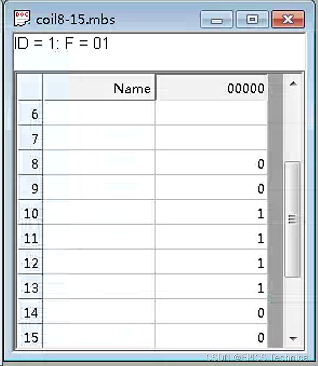
2、线圈2,起始地址为8,数量为8,软件设置如下(功能码1):
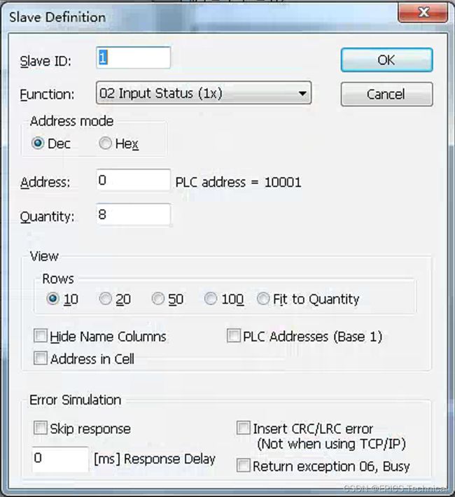
3、离散输入,起始地址为0,数量为8,软件设置如下(功能码2):
使用EPICS Modbus模块对以上modbus设备进行读写,过程如下:
使用makeBaseApp.pl构建IOC程序框架,并且在configure/RELEASE中指定base所在路径以及所需要的支持模块modbus路径。在程序的src路径下Makefile中指定要添加的数据块定义文件和库文件。
在程序的Db目录下,编写如下模板文件:
1) bo_bit.template:用于写modbus设备的单线圈
record(bo,"$(P)$(R)") {
    field(DTYP,"asynUInt32Digital")
    field(OUT,"@asynMask($(PORT) $(OFFSET) 0x1)")
    field(ZNAM,"$(ZNAM)")
    field(ONAM,"$(ONAM)")
}
2)bi_bit.template:用于读modbus设备的线圈状态或者离散输入状态
record(bi,"$(P)$(R)") {
    field(DTYP,"asynUInt32Digital")
    field(INP,"@asynMask($(PORT) $(OFFSET) 0x1)")
    field(SCAN,"$(SCAN)")
    field(ZNAM,"$(ZNAM)")
    field(ONAM,"$(ONAM)")
    field(ZSV,"$(ZSV)")
    field(OSV,"$(OSV)")
}
3)wfo_bit.template:用于一次写modbus设备的多个线圈
record(waveform,"$(P)$(R)") {
    field(DTYP,"asynInt32ArrayOut")
    field(INP,"@asyn($(PORT) $(OFFSET=0))MODBUS_DATA")
    field(FTVL,"ULONG")
    field(NELM,"$(NELM)")
}
4) wfi_bit.template:用于读取modbus设备多个线圈状态或这多个离散输入状态。
record(waveform,"$(P)$(R)") {
    field(DTYP,"asynInt32ArrayIn")
    field(INP,"@asyn($(PORT) $(OFFSET=0))MODBUS_DATA")
    field(SCAN,"$(SCAN)")
    field(FTVL,"ULONG")
    field(NELM,"$(NELM)")
}
将以上模板文件添加到相同路径下Makefile文件中:
...
DB +=  bo_bit.template
DB +=  bi_bit.template
DB +=  wfo_bit.template
DB +=  wfi_bit.template
...
回到IOC顶层目录,执行make命令,编译这个IOC。
进入到启动目录iocBoot/iocmodbusbit中,编写记录实例化文件:
1)coil_bo_bits.substitutions:用于实例化8个bo记录,每个bo写modbus设备1个线圈。
file "../../db/bo_bit.template" { pattern
{P,        R,             PORT,       OFFSET,   ZNAM,   ONAM}
{COUT:,    CO0B,     C0_Out_Bits,     0,        Low,    High}
{COUT:,    CO1B,     C0_Out_Bits,     1,        Low,    High}
{COUT:,    CO2B,     C0_Out_Bits,     2,        Low,    High}
{COUT:,    CO3B,     C0_Out_Bits,     3,        Low,    High}
{COUT:,    CO4B,     C0_Out_Bits,     4,        Low,    High}
{COUT:,    CO5B,     C0_Out_Bits,     5,        Low,    High}
{COUT:,    CO6B,     C0_Out_Bits,     6,        Low,    High}
{COUT:,    CO7B,     C0_Out_Bits,     7,        Low,    High}
}
2)coil_bi_bits.substitutions:用于实例化16个bi记录,每个bi读取modbus设备1个线圈状态。
file "../../db/bi_bit.template" { pattern
{P,        R,          PORT,         OFFSET,   ZNAM,   ONAM,  ZSV,       OSV,    SCAN}
{CIN:,    CI00B,     C0_In_Bits,     0,        Low,    High,  NO_ALARM,  MAJOR,  "I/O Intr"}
{CIN:,    CI01B,     C0_In_Bits,     1,        Low,    High,  NO_ALARM,  MAJOR,  "I/O Intr"}
{CIN:,    CI02B,     C0_In_Bits,     2,        Low,    High,  NO_ALARM,  MAJOR,  "I/O Intr"}
{CIN:,    CI03B,     C0_In_Bits,     3,        Low,    High,  NO_ALARM,  MAJOR,  "I/O Intr"}
{CIN:,    CI04B,     C0_In_Bits,     4,        Low,    High,  NO_ALARM,  MAJOR,  "I/O Intr"}
{CIN:,    CI05B,     C0_In_Bits,     5,        Low,    High,  NO_ALARM,  MAJOR,  "I/O Intr"}
{CIN:,    CI06B,     C0_In_Bits,     6,        Low,    High,  NO_ALARM,  MAJOR,  "I/O Intr"}
{CIN:,    CI07B,     C0_In_Bits,     7,        Low,    High,  NO_ALARM,  MAJOR,  "I/O Intr"}
{CIN:,    CI08B,     C1_In_Bits,     0,        Low,    High,  NO_ALARM,  MAJOR,  "I/O Intr"}
{CIN:,    CI09B,     C1_In_Bits,     1,        Low,    High,  NO_ALARM,  MAJOR,  "I/O Intr"}
{CIN:,    CI10B,     C1_In_Bits,     2,        Low,    High,  NO_ALARM,  MAJOR,  "I/O Intr"}
{CIN:,    CI11B,     C1_In_Bits,     3,        Low,    High,  NO_ALARM,  MAJOR,  "I/O Intr"}
{CIN:,    CI12B,     C1_In_Bits,     4,        Low,    High,  NO_ALARM,  MAJOR,  "I/O Intr"}
{CIN:,    CI13B,     C1_In_Bits,     5,        Low,    High,  NO_ALARM,  MAJOR,  "I/O Intr"}
{CIN:,    CI14B,     C1_In_Bits,     6,        Low,    High,  NO_ALARM,  MAJOR,  "I/O Intr"}
{CIN:,    CI15B,     C1_In_Bits,     7,        Low,    High,  NO_ALARM,  MAJOR,  "I/O Intr"}
}
3)dis_bi_bits.substitutions:用于实例化8个bi记录,每个bi取modbus设备离散输入状态。
file "../../db/bi_bit.template" { pattern
{P,        R,          PORT,         OFFSET,   ZNAM,   ONAM,  ZSV,       OSV,    SCAN}
{DIN:,    DI00B,     D0_In_Bits,     0,        Low,    High,  NO_ALARM,  MAJOR,  "I/O Intr"}
{DIN:,    DI01B,     D0_In_Bits,     1,        Low,    High,  NO_ALARM,  MAJOR,  "I/O Intr"}
{DIN:,    DI02B,     D0_In_Bits,     2,        Low,    High,  NO_ALARM,  MAJOR,  "I/O Intr"}
{DIN:,    DI03B,     D0_In_Bits,     3,        Low,    High,  NO_ALARM,  MAJOR,  "I/O Intr"}
{DIN:,    DI04B,     D0_In_Bits,     4,        Low,    High,  NO_ALARM,  MAJOR,  "I/O Intr"}
{DIN:,    DI05B,     D0_In_Bits,     5,        Low,    High,  NO_ALARM,  MAJOR,  "I/O Intr"}
{DIN:,    DI06B,     D0_In_Bits,     6,        Low,    High,  NO_ALARM,  MAJOR,  "I/O Intr"}
{DIN:,    DI07B,     D0_In_Bits,     7,        Low,    High,  NO_ALARM,  MAJOR,  "I/O Intr"}
}
4)coil_wfo_bits.substitutions:实例化一个waveform记录,用于一次最多设置modbus设备8个线圈。
file "../../db/wfo_bit.template" { pattern
{P,        R,             PORT,       OFFSET,   NELM}
{COUT:,    WFO,            C0_Out_WF,         0,        8}
}
5) dis_wfi_bits.substitutions:实例化一个waveform记录,用于读取modbus设备8个离散输入的状态。
file "../../db/wfi_bit.template" { pattern
{P,        R,          PORT,         OFFSET,   , NELM ,    SCAN}
{DIN:,    WFI,         D0_In_Bits,     8,       8,  "I/O Intr"}
}
编写启动脚本st.cmd:
#!../../bin/linux-x86_64/modbuspoll

#- You may have to change modbuspoll to something else
#- everywhere it appears in this file

< envPaths

cd "${TOP}"

## Register all support components
dbLoadDatabase "dbd/modbuspoll.dbd"
modbuspoll_registerRecordDeviceDriver pdbbase

# 连接modbus设备
drvAsynIPPortConfigure("mpoll","192.168.3.15:502",0,0,1)
# 使用modbus tcp类型
modbusInterposeConfig("mpoll", 0 ,2000,0)

# 用于写线圈,起始地址0,每次写1个,一共写8次
drvModbusAsynConfigure("C0_Out_Bits", "mpoll", 0, 5,  0, 8, 0,  100, "mpoll")
# 用于写线圈,起始地址8,一次写8个线圈
drvModbusAsynConfigure("C0_Out_WF",   "mpoll", 0, 15, 8, 8, 0,  100, "mpoll")

# 用于读线圈,起始地址0,每次读取一个,一共读8次,轮询时间为500ms
drvModbusAsynConfigure("C0_In_Bits",  "mpoll", 0, 1,  0, 8, 0,  500, "mpoll")
# 用于读线圈,起始地址8,每次读取一个,一共读8次,轮询时间为500ms
drvModbusAsynConfigure("C1_In_Bits",  "mpoll", 0, 1,  8, 8, 0,  500, "mpoll")

# 用于读取离散输入,起始地址0,每次读取一个,读取8次,轮询时间100ms
drvModbusAsynConfigure("D0_In_Bits", "mpoll",  0,  2, 0, 8, 0,  100, "mpoll")

cd "${TOP}/iocBoot/${IOC}"
# 加载实例化记录
# 写线圈
dbLoadTemplate("coil_bo_bits.substitutions")
# 写线圈
dbLoadTemplate("coil_wfo_bits.substitutions")
# 读线圈
dbLoadTemplate("coil_bi_bits.substitutions")
# 读离散输入
dbLoadTemplate("dis_bi_bits.substitutions")
# 读离散输入
dbLoadTemplate("dis_wfi_bits.substitutions")

iocInit
启动这个IOC:
[root@localhost iocmodbusbit]# ../../bin/linux-x86_64/modbuspoll st.cmd
#!../../bin/linux-x86_64/modbuspoll
...
# bit write
drvModbusAsynConfigure("C0_Out_Bits", "mpoll", 0, 5,  0, 8, 0,  100, "mpoll")
# bit array write
drvModbusAsynConfigure("C0_Out_WF",   "mpoll", 0, 15, 8, 8, 0,  100, "mpoll")
# Coil bit Read
drvModbusAsynConfigure("C0_In_Bits",  "mpoll", 0, 1,  0, 8, 0,  500, "mpoll")
drvModbusAsynConfigure("C1_In_Bits",  "mpoll", 0, 1,  8, 8, 0,  500, "mpoll")
# Discrete bit Read
drvModbusAsynConfigure("D0_In_Bits", "mpoll",  0,  2, 0, 8, 0,  100, "mpoll")
cd "/usr/local/EPICS/program/modbuspoll/iocBoot/iocmodbusbit"
dbLoadTemplate("coil_bo_bits.substitutions")
dbLoadTemplate("coil_wfo_bits.substitutions")
dbLoadTemplate("coil_bi_bits.substitutions")
dbLoadTemplate("dis_bi_bits.substitutions")
dbLoadTemplate("dis_wfi_bits.substitutions")
iocInit
Starting iocInit
...
## Start any sequence programs
#seq sncxxx,"user=blctrl"
epics> dbl
COUT:CO0B
COUT:CO1B
COUT:CO2B
COUT:CO3B
COUT:CO4B
COUT:CO5B
COUT:CO6B
COUT:CO7B
COUT:WFO
DIN:WFI
CIN:CI00B
CIN:CI01B
CIN:CI02B
CIN:CI03B
CIN:CI04B
CIN:CI05B
CIN:CI06B
CIN:CI07B
CIN:CI08B
CIN:CI09B
CIN:CI10B
CIN:CI11B
CIN:CI12B
CIN:CI13B
CIN:CI14B
CIN:CI15B
DIN:DI00B
DIN:DI01B
DIN:DI02B
DIN:DI03B
DIN:DI04B
DIN:DI05B
DIN:DI06B
DIN:DI07B
1) COUT:CO0B~COUT:CO7B:bo记录,每个bo记录用于写一个线圈。
2)COUT:WF:waveform记录,用于一次写8个线圈。
3)DIN:WFI:waveform记录,用于读取8个离散输入。
4)CIN:CI00B~CIN:CI15B:bi记录,每个bi记录读取一个线圈状态。
5)DIN:DI00B~DIN:DI00B,bi记录,每个bi记录读取一个离散输入。
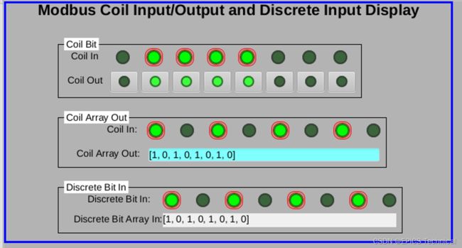
用css绘制控制界面,进行记录连接后,如下所示:
1)顶层窗口区域:Coil Out按钮写线圈,Coil In回读线圈状态
2)中间窗口区域:Coil Array Out可以一次最多写8个线圈,Coil In回读线圈状态。
3)底层窗口区域:用于读取离散输入,离散输入状态需要在modbus slave窗口中设置 ,Discrete Bit in 和Discrete Bit Array In都回读modbus slave窗口中设置的离散输入的状态。


