Verilog刷题笔记11
题目:
This exercise is an extension of module_shift. Instead of module ports being only single pins, we now have modules with vectors as ports, to which you will attach wire vectors instead of plain wires. Like everywhere else in Verilog, the vector length of the port does not have to match the wire connecting to it, but this will cause zero-padding or trucation of the vector. This exercise does not use connections with mismatched vector lengths.
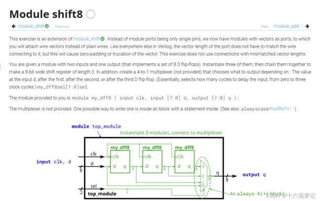
You are given a module with two inputs and one output (that implements a set of 8 D flip-flops). Instantiate three of them, then chain them together to make a 8-bit wide shift register of length 3. In addition, create a 4-to-1 multiplexer (not provided) that chooses what to output depending on : The value at the input d, after the first, after the second, or after the third D flip-flop. (Essentially, selects how many cycles to delay the input, from zero to three clock cycles.) my_dff8sel[1:0]sel
The module provided to you is: module my_dff8 ( input clk, input [7:0] d, output [7:0] q );
The multiplexer is not provided. One possible way to write one is inside an block with a statement inside. (See also: alwayscasemux9to1v)

我的解法:
module top_module (
    input clk,
    input [7:0] d,
    input [1:0] sel,
    output [7:0] q
);
    wire [7:0]A,B,C;
    my_dff8 dff1(clk,d,A);
    my_dff8 dff2(clk,A,B);
    my_dff8 dff3(clk,B,C);

    always @(*) begin
    case(sel)
            2'b00 : q = d;
            2'b01 : q = A;
            2'b10 : q = B;
            2'b11 : q = C;
    endcase
    end

endmodule
module top_module (
	input clk,
	input [7:0] d,
	input [1:0] sel,
	output reg [7:0] q
);

	wire [7:0] o1, o2, o3;		// output of each my_dff8

	// Instantiate three my_dff8s
	my_dff8 d1 ( clk, d, o1 );
	my_dff8 d2 ( clk, o1, o2 );
	my_dff8 d3 ( clk, o2, o3 );

	// This is one way to make a 4-to-1 multiplexer
	always @(*)		// Combinational always block
		case(sel)
			2'h0: q = d;
			2'h1: q = o1;
			2'h2: q = o2;
			2'h3: q = o3;
		endcase

endmodule
always与case知识点:
在 Verilog 中,always 关键字用于描述一个模块中的行为,它通常与时钟信号一起使用,用于定义组合逻辑或时序逻辑的行为。always 块中的语句将会在特定条件下被执行。
语法格式
always @ (posedge clk) begin
  // 在时钟信号的上升沿执行的语句
end

always @ (negedge reset) begin
  // 在复位信号的下降沿执行的语句
end

always @ (*) begin
  // 当任何敏感信号变化时执行的语句
end
时钟控制逻辑
在时序逻辑中,always 通常与时钟信号 (posedge/negedge) 结合使用,以实现在时钟信号的上升沿或下降沿触发的行为。这通常用于描述寄存器的行为。
always @ (posedge clk) begin
  // 在时钟信号的上升沿执行的语句
end
信号敏感逻辑
在组合逻辑中,always 可以使用 @(*) 来表示在任何敏感信号变化时触发的行为。这可用于描述纯组合逻辑的行为。
always @ (*) begin
  // 当任何敏感信号变化时执行的语句
end
重复执行
always 块中的语句将会在满足条件时重复执行。在时序逻辑中,通常用于描述寄存器或状态机的行为。
注意事项
always块中应当包含敏感信号列表或时钟条件,以限定执行的时机,避免产生非预期的行为。- 不当使用
always可能导致逻辑错误或综合问题,因此在设计中需谨慎使用。
在 Verilog 中,always 用于描述某些条件下的行为,而 case 语句用于在不同的情况下执行不同的动作。下面对它们的用法进行详细说明:
always 用法
always 关键字用于描述在特定条件下执行的行为。它通常与时钟信号一起使用,用于定义组合逻辑或时序逻辑的行为。在 always 块中的语句将会在特定条件下重复执行。
时钟控制逻辑
always @ (posedge clk) begin
  // 在时钟信号的上升沿执行的语句
end
信号敏感逻辑
always @ (*) begin
  // 当任何敏感信号变化时执行的语句
end
case 用法
case 语句用于根据某个表达式的值执行不同的动作。它可以简化多重条件的判断,使代码更加清晰和易读。
基本语法
case (expr)
  pattern1: statement1;
  pattern2: statement2;
  // ...
  default: default_statement;
endcase
其中,expr 是一个表达式,而 pattern1、pattern2 等是可能的表达式值,对应的语句将根据 expr 的值来执行。
示例
case (sel)
  2'b00: out = in1;
  2'b01: out = in2;
  2'b10: out = in3;
  default: out = 8'b0;
endcase
在这个示例中,根据 sel 的值选择不同的输入进行赋值给 out。
always 与 case 结合使用示例
always @ (*) begin
  case (sel)
    2'b00: out = in1;
    2'b01: out = in2;
    2'b10: out = in3;
    default: out = 8'b0;
  endcase
end
在这个题目中,always 响应任何敏感信号的变化,当 sel 的值发生变化时执行 case 语句中相应的逻辑。
这个部分编码 2'b00, 2'b01, 2'b10, 2'b11 是用来指定在 case 语句中选择分支的匹配条件。在这个例子中,sel 是一个两位的二进制信号。通过使用 2'b 表示法,我们可以指定每个条件的比特位值。
2'b00表示二进制值00。2'b01表示二进制值01。2'b10表示二进制值10。2'b11表示二进制值11。
这些条件将用于根据 sel 的不同值选择相应的分支。如果 sel 等于 2'b00,则 q 的值将被赋为 d;如果 sel 等于 2'b01,则 q 的值将被赋为 A;以此类推。这样,根据 sel 的值的不同,q 将会被赋予对应的值。
这种编码方式对于手动指定输入和输出的对应关系或状态转移表时非常常见,特别是在数字逻辑设计中经常会使用到。
