VTK笔记-图形相关-平面-vtkPlaneSource
vtkPlane
执行各种平面计算;
vtkPlane提供了各种平面计算的方法。其中包括将点投影到平面上、计算平面方程和返回平面法线。
vtkPlane是抽象类vtkImplicitFunction的具体实现。

接口
起点和法向量
之前学到的知识可以知道,平面可以使用一个点和过这个点与平面垂直的法向量来确定,也可以使用一个点和过这个点不平行的两条直线确定;
vtkPlane中记录了点的坐标Origin和法向量信息Normal,确定了唯一的平面;
double Normal[3];
double Origin[3];
vtkSetVector3Macro(Normal, double);
vtkGetVectorMacro(Normal, double, 3);
vtkSetVector3Macro(Origin, double);
vtkGetVectorMacro(Origin, double, 3);
移动平面
按指定的距离沿法线方向平移平面。
负值使平面朝相反方向移动。
void Push(double distance);
给定点在平面上的投影点计算
静态函数ProjectPoint,可以计算给定点x在给定平面上的投影点坐标xproj;
成员函数ProjectPoint,可以计算给定点x在当前平面上的投影点坐标xproj;
GeneralizedProjectPoint同ProjectPoint;
注意:normal不必归一化处理;
static void ProjectPoint(const double x[3], const double origin[3], const double normal[3], double xproj[3]);
void ProjectPoint(const double x[3], double xproj[3]);
static void GeneralizedProjectPoint(const double x[3], const double origin[3],
			const double normal[3], double xproj[3]);
void GeneralizedProjectPoint(const double x[3], double xproj[3]);
判断点是否满足平面公式
判断点是否满足平面公式,可以用来判断一个点是否在平面上;Evaluate返回值为0表示x在normal和origin表示的平面上;
inline double vtkPlane::Evaluate(double normal[3], double origin[3], double x[3])
{
  return normal[0] * (x[0] - origin[0]) + normal[1] * (x[1] - origin[1]) + normal[2] * (x[2] - origin[2]);
}
计算点到平面的距离
返回点x到由n*(x-p0)=0定义的平面的距离。
注意:法线n[3]必须是幅值=1。
inline double vtkPlane::DistanceToPlane(double x[3], double n[3], double p0[3])
{
#define vtkPlaneAbs(x) ((x) < 0 ? -(x) : (x))
	return (vtkPlaneAbs(n[0] * (x[0] - p0[0]) + n[1] * (x[1] - p0[1]) + n[2] * (x[2] - p0[2])));
}
计算线与平面的交点
过点p1和点p2的直线相交平面(过P0点,平面法向量为n)于点x;IntersectWithLine可以根据直线和平面信息计算出相交点x的坐标,t用来返回结果信息,当0<= t <=1时,直线与平面不相交;当t为VTK_LARGE_DOUBLE时,表示与平面平行,永不相交;
static int IntersectWithLine(const double p1[3], const double p2[3],
	double n[3], double p0[3], double& t, double x[3]);
int IntersectWithLine(const double p1[3], const double p2[3], double& t, double x[3]);
示例
计算给定点在平面上投影坐标
#include ![]()
vtkPlanes
平面凸集的隐函数;
vtkPlanes计算一组平面的隐式函数和函数梯度。这些平面必须定义一个凸空间。
函数值是通过评估每个提供的平面获得的交点(即,最大值)。因此,该值是点到由平面定义的凸区域的最大距离。函数梯度是函数值处的平面法线。请注意,法线必须指向凸区域之外。因此,负函数值意味着点在凸区域内。
有几种方法可以定义平面集。最常用的方法是提供一个vtkPoints实例和一个vtkDataArray实例(点定义平面上的点,法线对应平面法线。)其他两种专门的方法是:
1)提供六个定义摄影机视锥的平面;2)提供边界框;

接口
1.创建视锥体面
可以从相机接口 vtkCamera::GetFrustumPlanes()获取视锥体面信息,调用函数SetFrustumPlanes来生成6平面组成的视锥体面组合;
double Planes[24];
void SetFrustumPlanes(double planes[24]);
2.使用Box边缘
指定由边界框定义的六个平面的替代方法。
边界框是定义为(xmin,xmax,ymin,ymax,zmin,zmax)的六个向量。它定义了与x-y-z坐标轴正交的六个平面。
double Bounds[6];
void SetBounds(const double bounds[6]);
void SetBounds(double xmin, double xmax, double ymin, double ymax, double zmin, double zmax);
3.使用点集合和法向量集合
   vtkPoints* Points;
   vtkDataArray* Normals;
   vtkPlane* Plane;
   virtual void SetPoints(vtkPoints*);
   vtkGetObjectMacro(Points, vtkPoints);
   void SetNormals(vtkDataArray* normals);
   vtkGetObjectMacro(Normals, vtkDataArray);
   int GetNumberOfPlanes();
   vtkPlane* GetPlane(int i);
   void GetPlane(int i, vtkPlane* plane);
Points表示每个平面过的点的集合;
Normals表示每个平面的法向量集合;
Plane表示每个平面;
可以使用GetNumberOfPlanes获取vtkPlanes中平面个数;
可以使用GetPlane获取平面vtkPlane;
示例
#include 
vtkPlaneSource
创建位于平面中的四边形数组;
vtkPlaneSource创建一个由四边形组成的m*n数组,这些四边形排列为平面中的规则平铺。该平面是通过指定一个原点来定义的,然后指定另外两个与原点一起定义平面的两个轴的点。这些轴不必是正交的-所以你可以创建一个平行四边形(轴不能平行。)平面的分辨率(即细分的数量)由X分辨率和Y分辨率控制。
默认情况下,平面以原点为中心并垂直于z轴,宽度和高度的长度为1,分辨率设置为1。
该类中有三个便利的方法(即成员函数),帮助你很容易的移动平面。首先,SetNormal(), 允许你指定平面的法向量(plane normal)。这个方法的效果,就是使平面绕着平面中心转动,指向你所规定的方向。所谓的旋转,就是通过将当前平面的法向量与你所指定的法向量叉乘来实现的。第二,SetCenter(), 可以实现平面平移到你所指定的中心点坐标。第三, Push(), 是你能够将平面沿着法向量方向平移你所指定的距离,这是个非常有用的函数方法。如果Push的参数是负值,平面就沿着法向量的反方向移动。注意, SetNormal(), SetCenter() and Push() 这三个方法,修改了Origin、Point1和Point2实例变量。
注意:SetNormal()、SetCenter()和Push()方法修改了Origin、Point1和/或Point2实例变量。
注意:平面的法线将指向第一个轴(原点->点1)与第二个轴(原点->点2)的叉积方向。这也会影响生成的多边形的法线。
接口
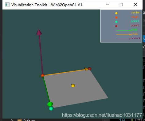
起点Origin/X方向Point1/Y方向Point2

Origin–>Point1构成了X方向;Origin–>Point2构成了Y方向;
平面的范围就是Origin,Point1,Point2,组成的平行四边形;
   double Origin[3];
   double Point1[3];
   double Point2[3];
   vtkSetVector3Macro(Origin, double);
   vtkGetVectorMacro(Origin, double, 3);
   void SetPoint1(double x, double y, double z);
   void SetPoint1(double pnt[3]);
   vtkGetVectorMacro(Point1, double, 3);
   void SetPoint2(double x, double y, double z);
   void SetPoint2(double pnt[3]);
   vtkGetVectorMacro(Point2, double, 3);
   vtkSetMacro(XResolution, int);
   vtkGetMacro(XResolution, int);
   vtkSetMacro(YResolution, int);
   vtkGetMacro(YResolution, int);

   void SetResolution(const int xR, const int yR);
   void GetResolution(int& xR, int& yR)
   {
     xR = this->XResolution;
     yR = this->YResolution;
   }
平面中心点和法向量
平面的方向与平面中心一起确定平面。
注意:不要使用此方法定义平面。相反,使用它围绕当前中心点旋转平面。
   double Normal[3];
   double Center[3];
   void SetCenter(double x, double y, double z);
   void SetCenter(double center[3]);
   vtkGetVectorMacro(Center, double, 3);
   void SetNormal(double nx, double ny, double nz);
   void SetNormal(double n[3]);
   vtkGetVectorMacro(Normal, double, 3);
平面移动/旋转
   void Push(double distance);
   void Rotate(double angle, double rotationAxis[3]);
输出点精度
设置/获取输出点所需的精度。
vtkAlgorithm::SINGLE_PRECISION - Output single-precision floating point.
vtkAlgorithm::DOUBLE_PRECISION - Output double-precision floating point.
int OutputPointsPrecision;
vtkSetMacro(OutputPointsPrecision, int);
vtkGetMacro(OutputPointsPrecision, int);
示例
#include 数据结果为一个正方型,原点Origin为(0,0,0);Point1为(1,0,0);Point2为(0,1,0);
由Origin指向Point1是X轴;
由Origin指向Point2是Y轴;
当设置Point1为(1,0.5,0);Point2为(0,1,0)时,面的形状时一个平行四边形;

引用文献
1.vtkPlaneSource 平面
2.PlaneSourceDemo
3.vtkPlane Class Reference