- VTK着色器MarbleShader代码学习(4)
点PY
三维渲染着色器学习
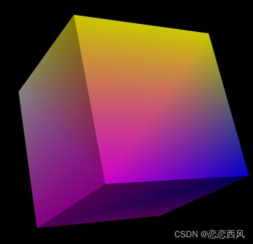
代码链接https://examples.vtk.org/site/Cxx/Shaders/MarbleShader/这段代码是一个使用VTK(VisualizationToolkit)实现的复杂着色器渲染示例,主要用于在3D模型上模拟大理石纹理效果。下面是对代码的详细解析:1.核心功能程序实现了一个基于Perlin噪声的大理石纹理着色器,主要特点包括:动态静脉纹理生成多级噪声叠加几何扭曲效果参数
- VTK中使用梯度幅值计算边缘
点PY
三维渲染服务器前端linux
#include#includevtkSmartPointerDetectEdgesWithGradient(vtkImageData*binaryVolume){</
- 口扫系统软件的架构设计流程
老猿的春天
三维c++口扫三维重建
[结构光图像流]↓解码结构光图案↓三角测量计算深度↓点云生成并去噪滤波↓实时配准/拼接(可选ICP/Odometry)↓网格重建(如MarchingCubes或BallPivoting)↓GPU显示(OpenGL/Open3D/VTK)
- 使用VTK还是OpenGL集成到qt程序里哪个好?
奇树谦
VTKqt开发语言
在Qt程序中集成VTK与OpenGL:选择哪个更好?在Qt程序中实现三维可视化时,开发者常常面临一个选择:是使用VTK(VisualizationToolkit)还是OpenGL(OpenGraphicsLibrary)。这两种技术各有优缺点,适用于不同的应用场景。本文将详细探讨它们的特点、优缺点以及如何选择适合你的项目的技术。一、VTK与OpenGL简介(一)VTK(VisualizationT
- vtk和opencv和opengl直接的区别是什么?
only-lucky
opencv人工智能计算机视觉
简介VTK、OpenCV和OpenGL是三个在计算机图形学、图像处理和可视化领域广泛使用的工具库,但它们在功能、应用场景和底层技术上存在显著差异。以下是它们的核心区别和特点对比:1.核心功能与定位工具核心功能主要应用领域VTK(VisualizationToolkit)三维可视化&科学计算,提供高级渲染、体绘制、交互式可视化医学影像、地质建模、流体力学仿真OpenCV(OpenSourceComp
- VTK知识学习(54)- 交互与Widget(五)
无所谓จุ๊บ
VTK学习VTK
1、前言选择拾取是人机交互过程的一个重要功能。在玩3D游戏时,场景中可能会存在多个角色,有时需要使用鼠标来选择所要控制的角色,这就需要用到拾取功能。另外,在某些三维图形的编辑软件中,经常需要编辑其中的一个点、一个面片或者一个局部区域,这也需要通过拾取功能来完成。VTK中定义了多个拾取功能的类,下图显示了这些拾取类的继承关系。VTK中的所有拾取类都继承自vkAbstractPicker类,利用这些类
- 在VTK中捕捉体绘制图像并实时图像处理
点PY
三维渲染图像处理人工智能VTK
0.概要这段代码实现了一个高级的医学图像可视化系统,主要特点包括双窗口交互式体绘制、图像后处理和实时同步。1.核心功能架构主窗口:3D体绘制视图(GPU加速的体积渲染)副窗口:2D截图视图(带高斯模糊后处理)交互机制:副窗口的交互操作会实时影响主窗口的3D视图2.关键组件分析2.1自定义交互器(CustomInteractorStyle)classCustomInteractorStyle:
- VTK体数据中RGBA切片保存流程
点PY
三维渲染算法VTK
0.概要这段代码实现了一个完整的图像处理流程,从多组分数据中提取切片、应用颜色映射、处理灰度图像,最终保存为PNG格式。下面我将详细解析每个部分的功能:1.颜色传输函数设置vtkSmartPointercolorTransferFunction=vtkSmartPointer::New();cv
- 在VTK中捕捉体绘制图像进阶(同步操作)
点PY
三维渲染microsoftwindows
0.概要这段代码实现了一个VTK(VisualizationToolkit)应用程序,主要功能是:读取DICOM医学图像序列并进行体绘制(VolumeRendering)创建一个主窗口显示3D体绘制结果创建一个副窗口显示主窗口的2D截图将副窗口中的交互操作(如旋转、缩放等)转发到主窗口,而不影响副窗口本身1.代码解析以下是代码的详细解析:初始化和头文件部分包含必要的VTK模块初始化宏和头文件初始化
- [VTK] 四元素实现旋转平移
comedate
VTK编译链接调试技术VTK旋转四元数
VTK实现旋转,有四元数的方案,也有vtkTransform的方案;主要示例代码如下://构造旋转四元数vtkQuaterniondrotation;rotation.SetRotationAngleAndAxis(vtkMath::RadiansFromDegrees(90.0),0.0,1.0,0.0);//构造旋转点四元数vtkQuaterniondp;p.Set(0.0,1.0,0.0,0
- VTK----VTK数据结构详解3(代码篇)
dylan55_you
VTK&VTK数据结构数据对象数据属性Ghost
上篇文章(VTK----VTK数据结构详解(计算机篇)-CSDN博客)从计算机数据结构(数组、链表等)的角度对数据数组、数据对象、数据属性的实现原理进行了说明,下面从代码的层面详细说明它们的使用及相关实现逻辑。1数据数组以vtkFloatArray为例,下面是它的使用及其VTK内部实现的代码:vtkNewscalars;scalars->InsertTuple1(0,1);voidvtkDataA
- vtkScalarBarActor 设置Label字体大小
长期向好的程序员
vtkc++
vtkNewscalarBar;constvtkNewlabelProperty;labelProperty->BoldOn();labelProperty->SetColor(1,1,1);labelProperty->SetOpacity(1);labelProperty->SetFontSize(10);scalarBar->SetLabelTextProperty(labelPropert
- VTK系统基础概念一
fang_chuan
C++VTK
转自东灵工作室的VTK系列教程,原文链接:http://blog.csdn.net/www_doling_net/article/details/26562595【本节对应原书中的第19页至第25页】VTK系统的总体概述,并讲解运用C++、Java、Tcl和Python等语言进行VTK应用程序开发时所需掌握的基本知识。首先我们从VTK系统的基本概念和对象模型抽象开始进行介绍,并在本章最后通过例子演
- VTK如何让部分单位不可见
最近遇到一个需求,需要让一个vtkDataSet中的部分单元不可见,查阅了一些资料大概有以下几种方式1.通过颜色映射表来进行,是最正规的做法vtkNewlut;//值为0不显示,主要是最后一个参数,透明度调为0lut->SetTableValue(0,0,0,0,0);//值为1显示为红色lut->SetTableValue(0,1,0,0);//设置一个颜色数组vtkNewcolors;//填充
- Visual Studio QT5.9.2构建VTK 8.0.1
YY3Y
教程visualstudioqtvtk
下载下载VTK8.0.1并解压缩文件(先解压VTK-8.0.1.zip,然后解压VTKData-8.0.1.zip)。(C:\VTK-8.0.1)下载链接:VTK-8.0.1.zipVTKData-8.0.1.zipCMake指定源代码的输入目标和解决方案文件的输出目的地。源代码目录:C:\VTK-8.0.1二进制文件输出目录:C:\VTK-8.0.1\build按下[Configure]并选择目
- QT 5.9.2+VTK8.0实现等高线绘制
csdndenglu
qt开发语言
项目下载链接:QT5.9.2+VTK8.0实现等高线绘制资源-CSDN文库示例如下:主要代码如下:#include"vtkRenderer.h"#include"vtkRenderWindow.h"#include"vtkRenderWindowInteractor.h"#include"vtkPolyDataMapper.h"#include"vtkVolume16Reader.h"#inclu
- 第4章:MeshLab核心库 VCGLib 多种格式的模型加载与保存
《雨声》
c++算法开发语言
✨功能概述使用VCGLib加载.ply/.obj/.stl网格;将VCGLib网格MyMesh转换为vtkPolyData;使用VTK显示该模型。依赖库VCGLib(头文件库)VTK(建议VTK9.x)完整C++代码示例//main.cpp#include#include#include//VTK头文件#include#include#include#include#include#include
- VTK API 详解(85):vtkImageActor - 图像显示 Actor
《雨声》
VTK常用API教程字典c++3d
一、简介vtkImageActor是VTK中专用于显示2D图像的Actor(演员)对象,可将vtkImageData渲染为二维图像纹理,显示在vtkRenderer中。它相当于为图像数据提供了一个在三维世界中可视化的外壳,适用于更灵活、更底层的图像显示场景。与vtkImageViewer2不同,vtkImageActor提供了更大的自由度,用户可手动控制渲染管线中每一部分(Renderer、Ren
- Sante DICOM Viewer CD/DVD患者读取器
SEO-狼术
sdk控件SanteDICOMViewerSanteDICOM
SanteDICOMViewerCD/DVD患者读取器SanteDICOMViewer是用于恢复、观察、存储、书目、管理和医学阅读的最佳软件工具之一。该程序是DICOM、切换器、PACS客户端、小型PACS服务器、CD/DVD患者读取器和其他设备的专业执行者。SanteDICOMViewer不是一个普通的DICOM查看器,它由dcmtk、itk和vtk等免费库组成,就像数百个其他DICOM查看器一
- 在Linux下,大恒相机、qt、c++、dlp4500开发的版本和开发说明
埃塞俄比亚在逃难民
c++开发语言
本篇主要介绍开发过程中的一些注意事项,具体代码没有涉及一、版本说明在后续的项目进展中,由于使用到pcl、vtk等三方库,查阅了各方资料,发现pyqt和pcl和vtk库总是报各种版本不兼容,或者缺失某文件的错误。所以最终还是采用c++去整体开发,这里归总一下所使用的各种库的版本:opencv4.5.5、pcl1.11.0、vtk8.2.0、qt55.12.8、boost1.71.0。注意:openc
- Python实现VTK - 自学笔记(3):三维数据处理与高级可视化
编程日记✧
智能医疗图像处理人工智能算法python开发语言开源
一、VTK渲染管线进阶解析在前两篇笔记中,我们已掌握立方体、圆锥等基础三维对象的创建与显示。本篇章将深入讲解VTK的核心架构——可视化管线(VisualizationPipeline),其工作流程可分为五层架构:1.数据源(Source)支持vtkPolyData(表面模型)、vtkImageData(体数据)等数据结构生成。例如通过vtkSTLReader读取STL模型文件:reader=vtk
- Python 实现 VTK - 自学笔记(2)
编程日记✧
智能医疗python笔记开发语言
1.数据处理与可视化进阶1.1复杂几何体生成(VTK原生实现)importvtk#创建圆锥体cone=vtk.vtkConeSource()cone.SetResolution(60)cone.SetHeight(5)cone.SetRadius(2)#添加变形效果(沿Y轴拉伸)transform=vtk.vtkTransform()transform.Scale(1,3,1)transform_
- Python实现VTK-自学笔记(5):在三维世界里自由舞蹈——高级交互与动态可视化
编程日记✧
智能医疗笔记python开发语言计算机视觉图像处理交互qt
深夜的台灯在屏幕上投下温暖的弧光,指尖敲击键盘的节奏逐渐与窗外雨滴声融为一体。这是我在VTK世界的第五次探险,此刻显示器里旋转的彩色分子模型仿佛在对我眨眼——它渴望被触摸、被塑造、被赋予生命。今天,就让我们用Python为这些沉默的数据注入灵魂,见证静态可视化如何蜕变为会呼吸的数字生命体!一、时空操控者:进阶SliderWidget实战下载必备库:pipinstallPyQT5-ihttps://
- 使用VTK库读取和显示DICOM图像,并访问图像像素
CnyhCode
python开发语言
VTK(VisualizationToolkit)是一个强大的开源图像处理和可视化库,它提供了许多用于读取、处理和显示DICOM图像的功能。在本文中,我们将使用VTK库来读取和显示单幅DICOM图像,并演示如何访问图像的像素值。首先,确保您已经安装了VTK库并设置好了开发环境。接下来,我们将逐步介绍如何使用VTK来完成这些任务。导入所需的库在开始之前,我们需要导入必要的库。VTK库提供了Pytho
- 跨平台三维可视化与图形库.VTK图形库.
yuanpan
信息可视化数据可视化
1.科学数据可视化体绘制(VolumeRendering)用于医学影像(如CT、MRI)、气象数据(如云层、流体模拟)的三维渲染,支持透明度、光照和颜色映射。等值面提取(Iso-Surfacing)通过算法(如MarchingCubes)从标量数据中提取表面(如医学图像中的器官轮廓)。流场可视化显示向量场(如风场、流体动力学),支持流线(Streamlines)、粒子追踪(ParticleTrac
- Qt+VTK+PCL联合开发手把手学习目录
点云SLAM
Qt+PCL+VTK3D数据可视化点云数据处理Qt+PCLPCL点云库SLAM计算机视觉
Qt+VTK+PCL联合开发手把手学习目录环境配置篇Qt+VTK+PCL第1讲:Qt与PCL简介之Qt与PCL的应用场景和Qt版本选择(Qt5/Qt6)及安装【附下载地址】第2讲:PCL库介绍及版本选择(1.12、1.13)以及Qt+PCL结合的基本架构第3讲:开发环境配置在Windows/Linux上配置Qt+PCLQt+VTK编译QVTKOpenGLNativeWidget部件第4讲:Win1
- Python实现VTK - 自学笔记(4):用Widgets实现三维交互控制
编程日记✧
智能医疗笔记人工智能健康医疗算法重构python交互
核心知识点交互器样式(vtkInteractorStyle):自定义鼠标/键盘交互逻辑三维控件(3DWidgets):使用预制控件实现复杂交互回调机制:实现动态数据更新参数化控制:通过控件调整算法参数importvtk#1.创建圆锥体数据源cone=vtk.vtkConeSource()cone.SetResolution(60)#2.创建映射器和演员mapper=vtk.vtkPolyDataM
- vtk 读取ply或者stl点云进行ICP配准(不可直接使用vtkPolyData)
应用魔导师
c++算法开发语言
在vtk中,读取ply或stl文件使用ICP进行点云配准时,需要注意不要直接使用vtkPolyData进行配准,这种方式会报错。vtkPLYReader读取的文件可能仅包含点数据,而没有显式的顶点定义。例如,PLY文件可能只列出点的坐标,而没有指定每个点是一个顶点。这时候,vtkPolyData中的Cells部分是空的,导致ICP无法找到单元,进而报错。vtkVertexGlyphFilter的作
- VTK|类似CloudCompare的比例尺实现2-vtk实现
奇树谦
VTKVTKqt5三维显示c++
文章目录实现类头文件实现类源文件调用逻辑关键问题缩放限制问题投影模式项目git链接实现类头文件以下是对你提供的ScaleBarController.h头文件添加详细注释后的版本,帮助你更清晰地理解每个成员和方法的用途,尤其是在VTK中的作用:#ifndefSCALEBARCONTROLLER_H#defineSCALEBARCONTROLLER_H#include#include#include#
- 【ITK】图像分割算法:GrabCut
雪易
图像图形处理付费专栏ITK完整教程人工智能计算机视觉深度学习GrabCut
很高兴在雪易的CSDN遇见你VTK技术爱好者QQ:870202403公众号:青予医械研发前言本文分享图像分割GrabCut算法,主要从算法原理和效果方面展开,希望对各位小伙伴有所帮助!感谢各位小伙伴的点赞+关注,小易会继续努力分享,一起进步!你的点赞就是我的动力(^U^)ノ~YOGrabCut算法来自论文“GrabCut”—InteractiveForegroundExtractionusingI
- PHP,安卓,UI,java,linux视频教程合集
cocos2d-x小菜
javaUIPHPandroidlinux
╔-----------------------------------╗┆
- 各表中的列名必须唯一。在表 'dbo.XXX' 中多次指定了列名 'XXX'。
bozch
.net.net mvc
在.net mvc5中,在执行某一操作的时候,出现了如下错误:
各表中的列名必须唯一。在表 'dbo.XXX' 中多次指定了列名 'XXX'。
经查询当前的操作与错误内容无关,经过对错误信息的排查发现,事故出现在数据库迁移上。
回想过去: 在迁移之前已经对数据库进行了添加字段操作,再次进行迁移插入XXX字段的时候,就会提示如上错误。
&
- Java 对象大小的计算
e200702084
java
Java对象的大小
如何计算一个对象的大小呢?
- Mybatis Spring
171815164
mybatis
ApplicationContext ac = new ClassPathXmlApplicationContext("applicationContext.xml");
CustomerService userService = (CustomerService) ac.getBean("customerService");
Customer cust
- JVM 不稳定参数
g21121
jvm
-XX 参数被称为不稳定参数,之所以这么叫是因为此类参数的设置很容易引起JVM 性能上的差异,使JVM 存在极大的不稳定性。当然这是在非合理设置的前提下,如果此类参数设置合理讲大大提高JVM 的性能及稳定性。 可以说“不稳定参数”
- 用户自动登录网站
永夜-极光
用户
1.目标:实现用户登录后,再次登录就自动登录,无需用户名和密码
2.思路:将用户的信息保存为cookie
每次用户访问网站,通过filter拦截所有请求,在filter中读取所有的cookie,如果找到了保存登录信息的cookie,那么在cookie中读取登录信息,然后直接
- centos7 安装后失去win7的引导记录
程序员是怎么炼成的
操作系统
1.使用root身份(必须)打开 /boot/grub2/grub.cfg 2.找到 ### BEGIN /etc/grub.d/30_os-prober ### 在后面添加 menuentry "Windows 7 (loader) (on /dev/sda1)" {
- Oracle 10g 官方中文安装帮助文档以及Oracle官方中文教程文档下载
aijuans
oracle
Oracle 10g 官方中文安装帮助文档下载:http://download.csdn.net/tag/Oracle%E4%B8%AD%E6%96%87API%EF%BC%8COracle%E4%B8%AD%E6%96%87%E6%96%87%E6%A1%A3%EF%BC%8Coracle%E5%AD%A6%E4%B9%A0%E6%96%87%E6%A1%A3 Oracle 10g 官方中文教程
- JavaEE开源快速开发平台G4Studio_V3.2发布了
無為子
AOPoraclemysqljavaeeG4Studio
我非常高兴地宣布,今天我们最新的JavaEE开源快速开发平台G4Studio_V3.2版本已经正式发布。大家可以通过如下地址下载。
访问G4Studio网站
http://www.g4it.org
G4Studio_V3.2版本变更日志
功能新增
(1).新增了系统右下角滑出提示窗口功能。
(2).新增了文件资源的Zip压缩和解压缩
- Oracle常用的单行函数应用技巧总结
百合不是茶
日期函数转换函数(核心)数字函数通用函数(核心)字符函数
单行函数; 字符函数,数字函数,日期函数,转换函数(核心),通用函数(核心)
一:字符函数:
.UPPER(字符串) 将字符串转为大写
.LOWER (字符串) 将字符串转为小写
.INITCAP(字符串) 将首字母大写
.LENGTH (字符串) 字符串的长度
.REPLACE(字符串,'A','_') 将字符串字符A转换成_
- Mockito异常测试实例
bijian1013
java单元测试mockito
Mockito异常测试实例:
package com.bijian.study;
import static org.mockito.Mockito.mock;
import static org.mockito.Mockito.when;
import org.junit.Assert;
import org.junit.Test;
import org.mockito.
- GA与量子恒道统计
Bill_chen
JavaScript浏览器百度Google防火墙
前一阵子,统计**网址时,Google Analytics(GA) 和量子恒道统计(也称量子统计),数据有较大的偏差,仔细找相关资料研究了下,总结如下:
为何GA和量子网站统计(量子统计前身为雅虎统计)结果不同?
首先:没有一种网站统计工具能保证百分之百的准确出现该问题可能有以下几个原因:(1)不同的统计分析系统的算法机制不同;(2)统计代码放置的位置和前后
- 【Linux命令三】Top命令
bit1129
linux命令
Linux的Top命令类似于Windows的任务管理器,可以查看当前系统的运行情况,包括CPU、内存的使用情况等。如下是一个Top命令的执行结果:
top - 21:22:04 up 1 day, 23:49, 1 user, load average: 1.10, 1.66, 1.99
Tasks: 202 total, 4 running, 198 sl
- spring四种依赖注入方式
白糖_
spring
平常的java开发中,程序员在某个类中需要依赖其它类的方法,则通常是new一个依赖类再调用类实例的方法,这种开发存在的问题是new的类实例不好统一管理,spring提出了依赖注入的思想,即依赖类不由程序员实例化,而是通过spring容器帮我们new指定实例并且将实例注入到需要该对象的类中。依赖注入的另一种说法是“控制反转”,通俗的理解是:平常我们new一个实例,这个实例的控制权是我
- angular.injector
boyitech
AngularJSAngularJS API
angular.injector
描述: 创建一个injector对象, 调用injector对象的方法可以获得angular的service, 或者用来做依赖注入. 使用方法: angular.injector(modules, [strictDi]) 参数详解: Param Type Details mod
- java-同步访问一个数组Integer[10],生产者不断地往数组放入整数1000,数组满时等待;消费者不断地将数组里面的数置零,数组空时等待
bylijinnan
Integer
public class PC {
/**
* 题目:生产者-消费者。
* 同步访问一个数组Integer[10],生产者不断地往数组放入整数1000,数组满时等待;消费者不断地将数组里面的数置零,数组空时等待。
*/
private static final Integer[] val=new Integer[10];
private static
- 使用Struts2.2.1配置
Chen.H
apachespringWebxmlstruts
Struts2.2.1 需要如下 jar包: commons-fileupload-1.2.1.jar commons-io-1.3.2.jar commons-logging-1.0.4.jar freemarker-2.3.16.jar javassist-3.7.ga.jar ognl-3.0.jar spring.jar
struts2-core-2.2.1.jar struts2-sp
- [职业与教育]青春之歌
comsci
教育
每个人都有自己的青春之歌............但是我要说的却不是青春...
大家如果在自己的职业生涯没有给自己以后创业留一点点机会,仅仅凭学历和人脉关系,是难以在竞争激烈的市场中生存下去的....
&nbs
- oracle连接(join)中使用using关键字
daizj
JOINoraclesqlusing
在oracle连接(join)中使用using关键字
34. View the Exhibit and examine the structure of the ORDERS and ORDER_ITEMS tables.
Evaluate the following SQL statement:
SELECT oi.order_id, product_id, order_date
FRO
- NIO示例
daysinsun
nio
NIO服务端代码:
public class NIOServer {
private Selector selector;
public void startServer(int port) throws IOException {
ServerSocketChannel serverChannel = ServerSocketChannel.open(
- C语言学习homework1
dcj3sjt126com
chomework
0、 课堂练习做完
1、使用sizeof计算出你所知道的所有的类型占用的空间。
int x;
sizeof(x);
sizeof(int);
# include <stdio.h>
int main(void)
{
int x1;
char x2;
double x3;
float x4;
printf(&quo
- select in order by , mysql排序
dcj3sjt126com
mysql
If i select like this:
SELECT id FROM users WHERE id IN(3,4,8,1);
This by default will select users in this order
1,3,4,8,
I would like to select them in the same order that i put IN() values so:
- 页面校验-新建项目
fanxiaolong
页面校验
$(document).ready(
function() {
var flag = true;
$('#changeform').submit(function() {
var projectScValNull = true;
var s ="";
var parent_id = $("#parent_id").v
- Ehcache(02)——ehcache.xml简介
234390216
ehcacheehcache.xml简介
ehcache.xml简介
ehcache.xml文件是用来定义Ehcache的配置信息的,更准确的来说它是定义CacheManager的配置信息的。根据之前我们在《Ehcache简介》一文中对CacheManager的介绍我们知道一切Ehcache的应用都是从CacheManager开始的。在不指定配置信
- junit 4.11中三个新功能
jackyrong
java
junit 4.11中两个新增的功能,首先是注解中可以参数化,比如
import static org.junit.Assert.assertEquals;
import java.util.Arrays;
import org.junit.Test;
import org.junit.runner.RunWith;
import org.junit.runn
- 国外程序员爱用苹果Mac电脑的10大理由
php教程分享
windowsPHPunixMicrosoftperl
Mac 在国外很受欢迎,尤其是在 设计/web开发/IT 人员圈子里。普通用户喜欢 Mac 可以理解,毕竟 Mac 设计美观,简单好用,没有病毒。那么为什么专业人士也对 Mac 情有独钟呢?从个人使用经验来看我想有下面几个原因:
1、Mac OS X 是基于 Unix 的
这一点太重要了,尤其是对开发人员,至少对于我来说很重要,这意味着Unix 下一堆好用的工具都可以随手捡到。如果你是个 wi
- 位运算、异或的实际应用
wenjinglian
位运算
一. 位操作基础,用一张表描述位操作符的应用规则并详细解释。
二. 常用位操作小技巧,有判断奇偶、交换两数、变换符号、求绝对值。
三. 位操作与空间压缩,针对筛素数进行空间压缩。
&n
- weblogic部署项目出现的一些问题(持续补充中……)
Everyday都不同
weblogic部署失败
好吧,weblogic的问题确实……
问题一:
org.springframework.beans.factory.BeanDefinitionStoreException: Failed to read candidate component class: URL [zip:E:/weblogic/user_projects/domains/base_domain/serve
- tomcat7性能调优(01)
toknowme
tomcat7
Tomcat优化: 1、最大连接数最大线程等设置
<Connector port="8082" protocol="HTTP/1.1"
useBodyEncodingForURI="t
- PO VO DAO DTO BO TO概念与区别
xp9802
javaDAO设计模式bean领域模型
O/R Mapping 是 Object Relational Mapping(对象关系映射)的缩写。通俗点讲,就是将对象与关系数据库绑定,用对象来表示关系数据。在O/R Mapping的世界里,有两个基本的也是重要的东东需要了解,即VO,PO。
它们的关系应该是相互独立的,一个VO可以只是PO的部分,也可以是多个PO构成,同样也可以等同于一个PO(指的是他们的属性)。这样,PO独立出来,数据持

