高可用性网络在企业网中的应用
高可用性网络在企业网中的应用
下列信息只供参考
1 路由设备 vrrp http://609650290.blog.51cto.com/5628230/965374
2 网络接口 bond http://609650290.blog.51cto.com/5628230/962770
3 服务器 群集 (下一篇,敬请期待)
广域网链路中的应用
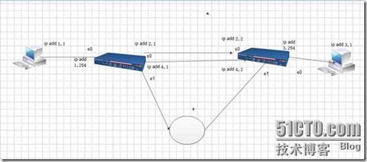
案例一
浮动静态路由
浮动静态路由是一种特殊的静态路由,通过配置一个比主路由的管理距离更大的静态路由,保证网络中主路由失效的情况下,提供备份路由。但在主路由存在的情况下它不会出现在路由表中。浮动静态路由主要用于拔号备份
静态路由的用处是当以太链路优先选择,当以太链路出现故障的时候,选用串行链路,而在以太链路恢复后,再优先选以太链路。
步骤一
路由器r1的配置
R1
Int e0
Ip add 192.168.1.254 24
Int e1
Ip add 192.168.4.1 24
Int s0
Ip add 192.168.2.1 24
路由器r2的配置
R1
Int e0
Ip add 192.168.3.254 24
Int e1
Ip add 192.168.4.2 24
Int s0
Ip add 192.168.2.2 24
在r1上配置ospf
ospf enable
int eo
ospf enable area 0
int s0
ospf enable area 0
步骤二
在r1上配置ospf
ospf enable
int eo
ospf enable area 0
int s0
ospf enable area 0
在r2上配置ospf
ospf enable
int eo
ospf enable area 0
int s0
ospf enable area 0
步骤三
配置静态路由
R1
Ip route-static 192.168.3.0 24 192.168.4.2
R2
Ip route-static 192.168.1.0 24 192.168.4.1
R1的路由信息

结果

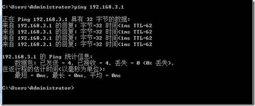
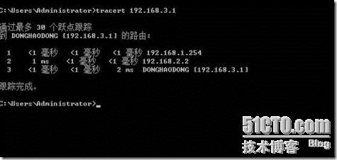
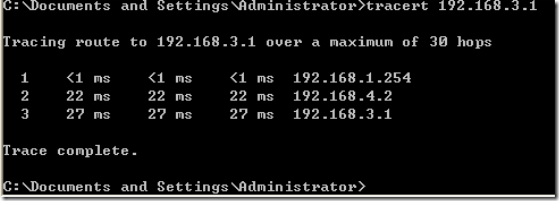
跟踪
R1路由表

断开s0口
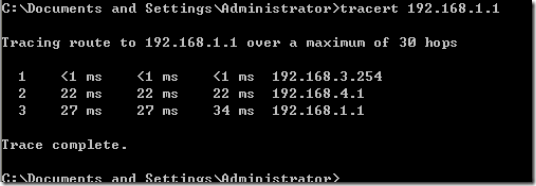
案例二
指定备份端口
步骤一
路由器r1的配置
R1
Int e0
Ip add 192.168.1.254 24
Int e1
Ip add 192.168.4.1 24
Int s0
Ip add 192.168.2.1 24
路由器r2的配置
R1
Int e0
Ip add 192.168.3.254 24
Int e1
Ip add 192.168.4.2 24
Int s0
Ip add 192.168.2.2 24
步骤二
配置静态路由
r1
ip route-static 192.168.3.0 24 192.168.2.2
r2
ip route-static 192.168.1.0 24 192.168.2.1
步骤三
r1
int s0 骨干链路接口
standby interface s1 指明为备份端口
standby timer enable-delay 10 启用备份接口延迟
standby timer disable-delay 10 启用主干接口延迟
r2
int s0 骨干链路接口
standby interface s1 指明为备份端口
standby timer enable-delay 10 启用备份接口延迟
standby timer disable-delay 10 启用主干接口延迟
结果
Routing Tables:
Destination/Mask Proto Pref Metric Nexthop Interface
127.0.0.0/8 Direct 0 0 127.0.0.1 LoopBack0
127.0.0.1/32 Direct 0 0 127.0.0.1 LoopBack0
192.168.1.0/24 Direct 0 0 192.168.1.254 Ethernet0
192.168.1.254/32 Direct 0 0 127.0.0.1 LoopBack0
192.168.2.0/24 Direct 0 0 192.168.2.2 Serial0
192.168.2.1/32 Direct 0 0 127.0.0.1 LoopBack0
192.168.2.2/32 Direct 0 0 192.168.2.2 Serial0
192.168.3.0/24 Static 60 0 192.168.2.2 Serial0
Routing Tables:
Destination/Mask Proto Pref Metric Nexthop Interface
127.0.0.0/8 Direct 0 0 127.0.0.1 LoopBack0
127.0.0.1/32 Direct 0 0 127.0.0.1 LoopBack0
192.168.1.0/24 Static 60 0 192.168.2.1 Serial0
192.168.2.0/24 Direct 0 0 192.168.2.1 Serial0
192.168.2.1/32 Direct 0 0 192.168.2.1 Serial0
192.168.2.2/32 Direct 0 0 127.0.0.1 LoopBack0
192.168.3.0/24 Direct 0 0 192.168.3.254 Ethernet0
192.168.3.254/32 Direct 0 0 127.0.0.1 LoopBack0
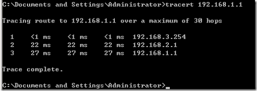
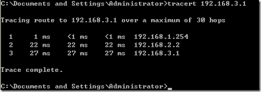
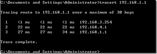
关闭端口s0
Routing Tables:
Destination/Mask Proto Pref Metric Nexthop Interface
127.0.0.0/8 Direct 0 0 127.0.0.1 LoopBack0
127.0.0.1/32 Direct 0 0 127.0.0.1 LoopBack0
192.168.1.0/24 Direct 0 0 192.168.1.254 Ethernet0
192.168.1.254/32 Direct 0 0 127.0.0.1 LoopBack0
192.168.3.0/24 Static 60 0 192.168.4.2 Serial1
192.168.4.0/24 Direct 0 0 192.168.4.2 Serial1
192.168.4.1/32 Direct 0 0 127.0.0.1 LoopBack0
192.168.4.2/32 Direct 0 0 192.168.4.2 Serial1
Routing Tables:
Destination/Mask Proto Pref Metric Nexthop Interface
127.0.0.0/8 Direct 0 0 127.0.0.1 LoopBack0
127.0.0.1/32 Direct 0 0 127.0.0.1 LoopBack0
192.168.1.0/24 Static 60 0 192.168.4.1 Serial1
192.168.3.0/24 Direct 0 0 192.168.3.254 Ethernet0
192.168.3.254/32 Direct 0 0 127.0.0.1 LoopBack0
192.168.4.0/24 Direct 0 0 192.168.4.1 Serial1
192.168.4.1/32 Direct 0 0 192.168.4.1 Serial1
192.168.4.2/32 Direct 0 0 127.0.0.1 LoopBack0
![clip_image016[1] clip_image016[1]](http://img1.51cto.com/attachment/201209/9/5628230_1347182505ZzoJ.gif)
案例三
链路捆绑
指的是在不改变现有网络设备以及原有布线的条件下,使用专用的软件或软硬件结合的产品,把多条交换机到服务器或交换机到交换机的数据通道捆绑起来,形成一条逻辑上的高带宽数据链路,满足高带宽应用如多媒体应用和视频点播的需要。而且还可以增加网络的负载均衡能力以及容错性,极大地提高整个系统的性能。
步骤一
路由器r1的配置、 r1和r2的s0,e1 接口不能有地址
int Virtual-Template 1
ip add 192.168.6.1 24
int s0
ppp mp interface Virtual-Template 1 把s0加入到虚拟口
int e1
ppp mp interface Virtual-Template 1把e1加入到虚拟口
r2的配置
int Virtual-Template 1
ip add 192.168.6.2 24
int s0
ppp mp interface Virtual-Template 1 把s0加入到虚拟口
int e1
ppp mp interface Virtual-Template 1把e1加入到虚拟口
步骤二 打开端口ppp协商功能
R1
int s0
ppp mp 打开端口ppp协商功能
int e1
ppp mp 打开端口ppp协商功能
r2
int s0
ppp mp 打开端口ppp协商功能
int e1
ppp mp 打开端口ppp协商功能
Routing Tables:
Destination/Mask Proto Pref Metric Nexthop Interface
127.0.0.0/8 Direct 0 0 127.0.0.1 LoopBack0
127.0.0.1/32 Direct 0 0 127.0.0.1 LoopBack0
192.168.1.0/24 Direct 0 0 192.168.1.254 Ethernet0
192.168.1.254/32 Direct 0 0 127.0.0.1 LoopBack0
192.168.3.0/24 Static 60 0 192.168.6.2 Virtual-Template1
192.168.6.0/24 Direct 0 0 192.168.6.1 Virtual-Template1
192.168.6.1/32 Direct 0 0 127.0.0.1 LoopBack0
Routing Tables:
Destination/Mask Proto Pref Metric Nexthop Interface
127.0.0.0/8 Direct 0 0 127.0.0.1 LoopBack0
127.0.0.1/32 Direct 0 0 127.0.0.1 LoopBack0
192.168.1.0/24 Static 60 0 192.168.6.1 Virtual-Template1
192.168.3.0/24 Direct 0 0 192.168.3.254 Ethernet0
192.168.3.254/32 Direct 0 0 127.0.0.1 LoopBack0
192.168.6.0/24 Direct 0 0 192.168.6.2 Virtual-Template1
192.168.6.2/32 Direct 0 0 127.0.0.1 LoopBack0
结果
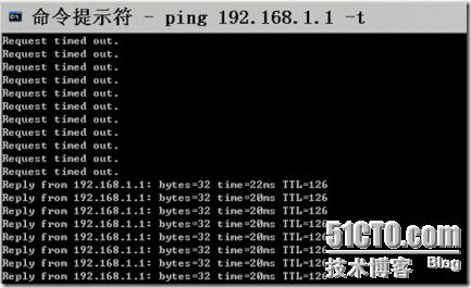


关闭端口s0

可以通信
重新打开s0
![clip_image025[1] clip_image025[1]](http://img1.51cto.com/attachment/201209/9/5628230_134718255713af.gif)
![clip_image027[1] clip_image027[1]](http://img1.51cto.com/attachment/201209/9/5628230_1347182563HvSg.gif)