端口镜像
端口镜像
一.本地端口镜像
本地端口镜像是在同一台交换机上进行镜像,应用范围比较小,在一个企业网中要跨越数十台交换机,所以本地端口镜像不经常用。
(1)配置准备
确定了镜像源端口,确定了被镜像报文的方向:inbound 表示仅对端口接收的报文进行镜像,outbound 表示仅对端口发送的报文进行镜像,both 表示同时对端口接收和发送的报文进行镜像确定了镜像目的端口。
(2)配置举例
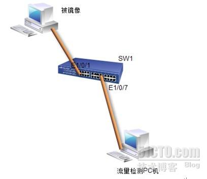
镜像源端口为 Ethernet1/0/1,对端口接收和发送的报文都进行镜像
镜像目的端口为 Ethernet1/0/7
(3)拓扑
(4)试验步骤
配置有三种
配置 1:
<Quidway> system-view
System View: return to User View with Ctrl+Z.
[Quidway] mirroring-group 1 local 在本地端口源镜像组
[Quidway] interface Ethernet1/0/7
[Quidway-Ethernet1/0/7] monitor-port 监控端口
[Quidway-Ethernet1/0/7] quit
[Quidway] interface Ethernet1/0/1
[Quidway-Ethernet1/0/1] mirroring-port both 被监控端口和监控的流量控制方向
配置2:
<Quidway> system-view
System View: return to User View with Ctrl+Z.
[Quidway] mirroring-group 1 local
[Quidway] interface Ethernet1/0/7
[Quidway-Ethernet1/0/7] mirroring-group 1 monitor-port
[Quidway-Ethernet1/0/7] quit
[Quidway] interface Ethernet1/0/1
[Quidway-Ethernet1/0/1] mirroring-group 1 mirroring-port both
配置 3:
<Quidway> system-view
System View: return to User View with Ctrl+Z.
[Quidway] mirroring-group 1 local
[Quidway] mirroring-group 1 monitor-port Ethernet1/0/7
[Quidway] mirroring-group 1 mirroring-port Ethernet1/0/1 both
二.远程端口镜像(RSPAN)
RSPAN (Remote Switched Port Analyzer,远程交换端口分析),即远程端口镜像,突破了被镜像端口和镜像端口必须在同一台交换机上的限制,使被镜像端口和镜像端口可以跨越网络中的多个设备,从而方便网管人员对远程交换机设备进行管理。
RSPAN 的应用示意图如下所示。
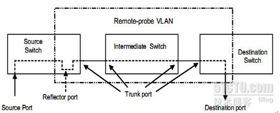
实现了RSPAN 功能的交换机分为三种:
源交换机:被监测的端口所在的交换机,负责将需要镜像的流量在Remote-probe VLAN 上做二层转发,转发给中间交换机或目的交换机。
中间交换机:网络中处于源交换机和目的交换机之间的交换机,通过 Remote-probe VLAN 把镜像流量传输给下一个中间交换机或目的交换机。如果源交换机与目的交换机直接相连,则不存在中间交换机。
目的交换机:远程镜像目的端口所在的交换机,将从Remote-probe VLAN 接收到的镜像流量通过镜像目的端口转发给监控设备。
配置准备
确定了源交换机、中间交换机、目的交换机
确定了镜像源端口、反射端口、镜像目的端口、Remote-probe VLAN
通过配置保证了 Remote-probe VLAN 内从源交换机到目的交换机的二层互通 性
确定了被监控报文的方向
中间交换机、目的交换机支持按VLAN 不学习 MAC 的功能,并且把一个VLAN
配置成 Remote-probe VLAN 后,系统会在该VLAN 下禁止 MAC 地址学习
如果要配置基于 MAC 的远程镜像,需要确定配置的MAC 地址必须是 MAC 地
址表项中存在的静态 MAC 地址
如果要配置基于VLAN 的远程镜像,需要确定相应的VLAN ID
配置举例
1. 组网需求
Switch A 通过 Ethernet1/0/2 和数据检测设备相连
Switch A 的Trunk 端口Ethernet1/0/1和Switch B 的Trunk 端口Ethernet 1/0/1相连
Switch B 的Trunk 端口Ethernet1/0/2和Switch C 的Trunk 端口Ethernet 1/0/1相连
Switch C 的端口Ethernet1/0/10和 PC10相连
Switch C 的端口Ethernet1/0/20 和 PC20相连
需求为通过数据检测设备对 PC10和PC20 发送的报文进行监控和分析。
使用 RSPAN 功能实现该需求,进行如下配置。
定义VLAN10 为remote-probe VLAN
SwitchA 为目的交换机,连接数据监控设备的端口 Ethernet1/0/2 为镜像目的端口,Ethernet1/0/2 上不能使用STP
Switch B 为中间交换机
Switch C 为源交换机,Ethernet1/0/2 为镜像源端口,定义 Ethernet1/0/5 为反射端口。Ethernet1/0/5 为access 端口,并且不能使用STP。
2. 网络拓扑

3. 实验步骤
(1)Switch C 的配置
#进入视图模式
<Quidway> system-view
#创建remote-probe vlan并进入vlan视图
[Quidway] vlan 10
#定义当前vlan为remote-probe vlan
[Quidway-vlan10] remote-probe vlan enable
[Quidway-vlan10] quit
#进入与中间交换机连接的接口
[Quidway] interface ethernet1/0/1
#端口类型为trunk
[Quidway-Ethernet1/0/1] port link-type trunk
#配置端口trunk允许remote-probe vlan通过
[Quidway-Ethernet1/0/1] port trunk permit vlan 10
[Quidway-Ethernet1/0/1] quit
#配置远程源镜像组
[Quidway] mirroring-group 1 remote-source
#配置远程镜像源端口(监控PC10和PC20之间流量)
[Quidway] mirroring-group 1 mirroring-port ethernet1/0/10 outbound流量出去监控
[Quidway] mirroring-group 1 mirroring-port ethernet1/0/20 intbound流量进来监控
#配置远程反射端口,
[Quidway] mirroring-group 1 reflector-port ethernet1/0/5
#配置远程源镜像组的remote-probe vlan
[Quidway] mirroring-group 1 remote-probe vlan 10
#查看远程源镜像组的配置
[Quidway] display mirroring-group remote-source
(2)Switch B 的配置
<Quidway> system-view
#创建remote-probe vlan并进入vlan视图
[Quidway] vlan 10
#定义当前vlan为remote-probe vlan
[Quidway-vlan10] remote-probe vlan enable
[Quidway-vlan10] quit
#进入与目的交换机连接的端口
[Quidway] interface ethernet1/0/1
#端口类型为trunk
[Quidway-Ethernet1/0/1] port link-type trunk
#配置端口trunk允许remote-probe vlan通过
[Quidway-Ethernet1/0/1] port trunk permit vlan 10
[Quidway-Ethernet1/0/1] quit
#进入与源交换机连接的端口
[Quidway] interface ethernet1/0/2
#端口类型为trunk
[Quidway-Ethernet1/0/2] port link-type trunk
#配置端口trunk允许remote-probe vlan通过
[Quidway-Ethernet1/0/2] port trunk permit vlan 10
(3)Switch A 的配置
<Quidway> system-view
#创建remote-probe vlan并进入vlan视图
[Quidway] vlan 10
#定义当前vlan为remote-probe vlan
[Quidway-vlan10] remote-probe vlan enable
[Quidway-vlan10] quit
#进入与中间交换机连接的端口
[Quidway] interface ethernet1/0/1
#端口类型为trunk
[Quidway-Ethernet1/0/1] port link-type trunk
#配置端口trunk允许remote-probe vlan通过
[Quidway-Ethernet1/0/1] port trunk permit vlan 10
[Quidway-Ethernet1/0/1] quit
#配置远程目的镜像组
[Quidway] mirroring-group 1 remote-destination
#配置远程镜像组的目的端口
[Quidway] mirroring-group 1 monitor-port ethernet1/0/2
#配置远程目的镜像组的remote-probe vlan
[Quidway] mirroring-group 1 remote-probe vlan 10
#查看目的镜像组
[Quidway] display mirroring-group remote-destination
4.配置完后,用PC10主机和PC20进行通讯,查看