linux网卡的vlan配置
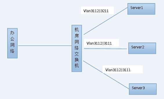
如果服务器上连的交换机端口已经预先设置了TRUNK,并允许特定的VLAN可以通过,那么服务器的网卡在配置时就必须指定所属的VLAN,否则就不通了,这种情形在虚拟化部署时较常见。
例如在一个办公环境中,办公所在VLAN为1020,虚拟化的物理主机上有两块万兆网卡,分属与3111和3112VLAN,这三个VLAN间可以互通,那么该如何配置呢?

一.首先要确认Linux系统内核是否已经支持VLAN功能:
当前使用内核以及操作系统版本:
[root@test ~]# cat /etc/redhat-release
Red Hat Enterprise Linux Server release 6.5 (Santiago)
首先yum安装vconfig,如果有就不用装了
yum install vconfig
查看核心是否提供VLAN 功能,执行
dmesg | grep -i 802
[root@test]# dmesg | grep -i 802
802.1Q VLAN Support v1.8 Ben Greear<[email protected]>
[root@test]# modprobe 8021q
[root@test~]#lsmod |grep 8021q //查看系统内核是否支持802.1q协议
8021q 18633 0
[root@test ~]# lspci //确认网卡驱动是否已经正常加载
00:00.0 Host bridge: Intel Corporation 440BX/ZX/DX - 82443BX/ZX/DX Host bridge (rev 01)
00:01.0 PCI bridge: Intel Corporation 440BX/ZX/DX - 82443BX/ZX/DX AGP bridge (rev 01)
00:07.0 ISA bridge: Intel Corporation 82371AB/EB/MB PIIX4 ISA (rev 08)
00:07.1 IDE interface: Intel Corporation 82371AB/EB/MB PIIX4 IDE (rev 01)
00:07.3 Bridge: Intel Corporation 82371AB/EB/MB PIIX4 ACPI (rev 08)
00:07.7 System peripheral: VMware Virtual Machine Communication Interface (rev 10)
00:0f.0 VGA compatible controller: VMware SVGA II Adapter
00:11.0 PCI bridge: VMware PCI bridge (rev 02)
00:15.0 PCI bridge: VMware PCI Express Root Port (rev 01)
00:15.1 PCI bridge: VMware PCI Express Root Port (rev 01)
00:15.2 PCI bridge: VMware PCI Express Root Port (rev 01)
二.物理网卡、子网卡、虚拟VLAN网卡的关系:
1.物理网卡:物理网卡这里指的是服务器上实际的网络接口设备,在系统中可以看到的,比如2个物理网卡分别对应是eth0和eth1这两个网络接口。
2. 子网卡:子网卡在这里并不是实际上的网络接口设备,但是可以作为网络接口在系统中出现,如eth0:1、eth1:2这种网络接口。它们必须要依赖于物理网卡,虽然可以与物理网卡的网络接口同时在系统中存在并使用不同的IP地址,而且也拥有它们自己的网络接口配置文件。但是当所依赖的物理网卡不启用时(Down状态)这些子网卡也将一同不能工作。
3.虚拟VLAN网卡:这些虚拟VLAN网卡也不是实际上的网络接口设备,也可以作为网络接口在系统中出现,但是与子网卡不同的是,他们没有自己的配置文件。他们只是通过将物理网加入不同的VLAN而生成的VLAN虚拟网卡。如果将一个物理网卡添加到多个VLAN当中去的话,就会有多个VLAN虚拟网卡出现,他们的信息以及相关的VLAN信息都是保存在/proc/net/vlan/config这个临时文件中的,而没有独自的配置文件。它们的网络接口名是eth0.1、eth1.2这种名字。
注:当需要启用VLAN虚拟网卡工作的时候,关联的物理网卡网络接口上必须没有IP地址的配置信息。
[root@test ~]# vi/etc/sysconfig/network-scripts/ifcfg-eth1
――――――――――――――――�C
DEVICE=eth1
ONBOOT=yes
BOOTPROTO=static
设定静态地址并且不给IP地址设定。
三、在Linux配置VLAN Trunk:
由于在Linux上eth1要被设定为Trunk,并且属于特定的3111VLAN。eth2也要被设定为Trunk,并且属于特定的3112VLAN。
1.将eth1添加到VLAN 3111中:
[root@test]# vconfig add eth1 3111
WARNING: Could not open/proc/net/vlan/config. Maybe you need to load the 8021q module, or maybe youare not using PROCFS??
Added VLAN with VID == 3111 to IF -:eth1:-
第一次添加VLAN虚拟网卡的时候就一定会出现上面的那句提示,原因是因为默认下/proc/net/vlan/config这个专门用来保存VLAN信息的文件是没有的。由于第一次添加VLAN网卡,那么这个文件也会被自动建立起来。另外,在/proc/目录下面的文件都是系统的临时文件,因此重新启动后必定丢失休息,所以在配置并测试VLAN成功后,可以将一些相关命令添加到rc.local这个启动脚本当中去。在执行该命令之前可以先到/proc/net/目录查看下,并不存在vlan文件夹,执行后会创建一个vlan文件夹,并生成config配置文件,以及对应的虚拟vlan网卡配置文件 eth1.3111等.
2.同样将eth2添加到VLAN3112中:
[root@test ~]# vconfig add eth2 3112
Added VLAN with VID == 3112 to IF -:eth2:-
3.检查添加的VLAN虚拟网卡信息:
[root@test ~]# cat/proc/net/vlan/config
--------------------------------------------------
VLAN Dev name | VLAN ID
Name-Type:VLAN_NAME_TYPE_RAW_PLUS_VID_NO_PAD
eth1.3111 | 3111 | eth1
eth2.3112 | 3112 | eth2
可以看到所有的VLAN虚拟网卡以及它们所归属的主物理网卡。
(如果只有一个物理网卡,也可配置为文件ifcfg-eth1.3111和ifcfg-eth1.3112)
4.为VLAN虚拟网卡设定IP地址并且进行启用:
[root@test ~]# ifconfig eth1.3111 192.168.20.1 up
[root@test ~]# ifconfig eth2.3112 192.168.30.1 up
这是临时的,可以这样做
利用cp命令复制接口的ip地址配置
cp ifcfg-eth1 ifcfg-eth1.3111
cp ifcfg-eth2 ifcfg-eth2.3112
把ifcfg-eth1和ifcfg-eth2中的原有地址去掉,再vi修改ifcfg-eth1.3111和ifcfg-eth2.3112文件,设置IP地址等信息。
5.最后重启network服务,令配置生效。
重新启动网络服务
[root@test ~]# service network restart
--------------------------------------------------
Shutting down interface eth1: [ OK ]
Shutting down interface eth2: [ OK ]
Shutting down loopback interface: [ OK ]
Bringing up loopback interface: [ OK ]
Bringing up interface eth1: [ OK ]
Bringing up interface eth2: [ OK ]
--------------------------------------------------
6.检查Linux系统下的所有网络接口信息:
[root@test ~]# ifconfig |more
到这里已经基本上将VLAN的主要配置完成了。
7、验证连通性
[root@test ~]# ping 192.168.20.254
PING 192.168.20.254 (192.168.20.254) 56(84) bytes of data.
64 bytes from 192.168.20.254: icmp_seq=1 ttl=255 time=8.42 ms
64 bytes from 192.168.20.254: icmp_seq=2 ttl=255 time=1.47 ms
64 bytes from 192.168.20.254: icmp_seq=3 ttl=255 time=1.51 ms
64 bytes from 192.168.20.254: icmp_seq=4 ttl=255 time=1.58 ms
^C
--- 192.168.20.254 ping statistics ---
4 packets transmitted, 4 received, 0% packet loss, time 6325ms
rtt min/avg/max/mdev = 1.470/2.550/8.427/2.400 ms
[root@test ~]# ping 192.168.30.254
PING 192.168.30.254 (192.168.30.254) 56(84) bytes of data.
64 bytes from 192.168.30.254: icmp_seq=1 ttl=255 time=8.42 ms
64 bytes from 192.168.30.254: icmp_seq=2 ttl=255 time=1.47 ms
64 bytes from 192.168.30.254: icmp_seq=3 ttl=255 time=1.51 ms
64 bytes from 192.168.30.254: icmp_seq=4 ttl=255 time=1.58 ms
^C
--- 192.168.30.254 ping statistics ---
4 packets transmitted, 4 received, 0% packet loss, time 6325ms
rtt min/avg/max/mdev = 1.470/2.550/8.427/2.400 ms