OpenRisc-19-or1200下linux的i2c(一)
解压得到如下文件目录:
注意啦,这里的i2c_top.v的顶层文件需要自己编写,因为需要在工程的更顶层将i2c_master_top.v里的输入输出信号组织成三态信号。
- module i2c_top(
- //wishbone interfaces
- wb_clk_i, wb_rst_i, arst_i,
- wb_adr_i, wb_dat_i, wb_dat_o,
- wb_we_i, wb_stb_i, wb_cyc_i, wb_ack_o, wb_inta_o,
- i2c_scl, i2c_sda
- );
- // wishbone signals
- input wb_clk_i; // master clock input
- input wb_rst_i; // synchronous active high reset
- input arst_i; // asynchronous reset
- input [2:0] wb_adr_i; // lower address bits
- input [7:0] wb_dat_i; // databus input
- output [7:0] wb_dat_o; // databus output
- input wb_we_i; // write enable input
- input wb_stb_i; // stobe/core select signal
- input wb_cyc_i; // valid bus cycle input
- output wb_ack_o; // bus cycle acknowledge output
- output wb_inta_o; // interrupt request signal output
- // i2c signals
- inout i2c_scl; //i2c clock signal
- inout i2c_sda; //i2c data signal
- i2c_master_top i2c_master_top(
- //wishbone interfaces
- .wb_clk_i(wb_clk_i),
- .wb_rst_i(wb_rst_i),
- .arst_i(arst_i),
- .wb_adr_i(wb_adr_i),
- .wb_dat_i(wb_dat_i),
- .wb_dat_o(wb_dat_o),
- .wb_we_i(wb_we_i),
- .wb_stb_i(wb_stb_i),
- .wb_cyc_i(wb_cyc_i),
- .wb_ack_o(wb_ack_o),
- .wb_inta_o(wb_inta_o),
- .scl_pad_i(scl_pad_i),
- .scl_pad_o(scl_pad_o),
- .scl_padoen_o(scl_padoen_o),
- .sda_pad_i(sda_pad_i),
- .sda_pad_o(sda_pad_o),
- .sda_padoen_o(sda_padoen_o)
- );
- assign i2c_scl = scl_padoen_o ? 1'bz : scl_pad_o;
- assign i2c_sda = sda_padoen_o ? 1'bz : sda_pad_o;
- assign scl_pad_i = i2c_scl;
- assign sda_pad_i = i2c_sda;
- endmodule
详细可以看看在改工程目录下的/doc说明文档,当中有改ipcore的使用说明。
接着在or1200_soc中例化改ipcore,然后添加到wishbone总线上,再定义好使用的中断号。
例化代码:
- `ifdef I2C
- wire [2:0] wb_i2c_adr_i;
- wire [7:0] wb_i2c_dat_i;
- wire [7:0] wb_i2c_dat_o;
- wire [31:0] wb_i2c_dat32_i;
- wire [31:0] wb_i2c_dat32_o;
- wire [3:0] wb_i2c_sel_i;
- wire wb_i2c_stb_i;
- wire wb_i2c_we_i;
- wire wb_i2c_ack_o;
- wire wb_i2c_cyc_i;
- wire wb_i2c_inta_o;
- i2c_master_top i2c_master_top(
- //wishbone interfaces
- .wb_clk_i(clk_cpu_40),
- .wb_rst_i(wb_rst_pad_i),
- .arst_i(1'b1),
- .wb_adr_i(wb_i2c_adr_i),
- .wb_dat_i(wb_i2c_dat_i),
- .wb_dat_o(wb_i2c_dat_o),
- .wb_we_i(wb_i2c_we_i),
- .wb_stb_i(wb_i2c_stb_i),
- .wb_cyc_i(wb_i2c_cyc_i),
- .wb_ack_o(wb_i2c_ack_o),
- .wb_inta_o(pic_ints[`APP_INT_I2C]),
- //i2c interface
- .scl_pad_i(scl_pad_i),
- .scl_pad_o(scl_pad_o),
- .scl_padoen_o(scl_padoen_o),
- .sda_pad_i(sda_pad_i),
- .sda_pad_o(sda_pad_o),
- .sda_padoen_o(sda_padoen_o)
- );
- assign i2c_scl = scl_padoen_o ? 1'bz : scl_pad_o;
- assign i2c_sda = sda_padoen_o ? 1'bz : sda_pad_o;
- assign scl_pad_i = i2c_scl;
- assign sda_pad_i = i2c_sda;
- assign wb_i2c_dat32_o[7:0] = (wb_i2c_sel_i[0] == 1'b1) ? wb_i2c_dat_o : 8'h0;
- assign wb_i2c_dat32_o[15:8] = (wb_i2c_sel_i[1] == 1'b1) ? wb_i2c_dat_o : 8'h0;
- assign wb_i2c_dat32_o[23:16] = (wb_i2c_sel_i[2] == 1'b1) ? wb_i2c_dat_o : 8'h0;
- assign wb_i2c_dat32_o[31:24] = (wb_i2c_sel_i[3] == 1'b1) ? wb_i2c_dat_o : 8'h0;
- assign wb_i2c_dat_i = wb_i2c_dat32_i[7:0];
- `else
- assign pic_ints[`APP_INT_I2C] = 'b0;
- `endif/*endif I2C*/
- /* the comment section below just instance for wb_conbus module */
- /*
- `ifdef I2C
- .s5_dat_i (wb_i2c_dat32_o),
- .s5_dat_o (wb_i2c_dat32_i),
- .s5_adr_o (wb_i2c_adr_i),
- .s5_sel_o (wb_i2c_sel_i),
- .s5_we_o (wb_i2c_we_i),
- .s5_cyc_o (wb_i2c_cyc_i),
- .s5_stb_o (wb_i2c_stb_i),
- .s5_ack_i (wb_i2c_ack_o),
- .s5_err_i (1'b0),
- .s5_rty_i (1'b0),
- // .s5_cab_i (),
- for switch cross bus :
- // .slave5_sel_addr ( `I2C_BASE_ADDR ),
- .wbs5_adr_i( wb_i2c_adr_i ),
- .wbs5_bte_i( ),
- .wbs5_cti_i( ),
- .wbs5_cyc_i( wb_i2c_cyc_i ),
- .wbs5_dat_i( wb_i2c_dat32_i ),
- .wbs5_sel_i( wb_i2c_sel_i ),
- .wbs5_stb_i( wb_i2c_stb_i ),
- .wbs5_we_i( wb_i2c_we_i ),
- .wbs5_ack_o( wb_i2c_ack_o ),
- .wbs5_err_o( 'b0 ),
- .wbs5_rty_o( 'b0 ),
- .wbs5_dat_o( wb_i2c_dat32_o ),
- */
中断号和地址:
- /* Interrupts */
- `define APP_INT_RES1 1:0
- `define APP_INT_UART 2
- `define APP_INT_KEY 3
- `define APP_INT_ETH 4
- `define APP_INT_I2C 5
- `define APP_INT_VGA_LCD 6
- `define APP_INT_RES 19:7
- /* Peripheral Addr ,modify by manual */
- `define FLASH_BASE_ADDR 4'hf //slave X address ,connect to FLASH
- `define SDRAM_BASE_ADDR 4'h0 //slave X address ,connect to DDR_SDRAM
- `define UART_BASE_ADDR 8'h90 //slave X address ,connect to UART
- `define GPIO_BASE_ADDR 8'h91 //slave X address
- `define ETH_BASE_ADDR 8'h92 //slave X address ,connect to ETH
- `define VGA_BASE_ADDR 8'h95 //slave X address, connect to VGA/LCD
- `define DMA_BASE_ADDR 8'hxx //slave X address,
- `define SRAM_BASE_ADDR 8'hxx //slave X address ,connect to SRAM
- `define SD_CARD_BASE_ADDR 8'h94 //slave X address ,connect to sd_card
- `define I2C_BASE_ADDR 8'h93 //slave X address ,connect to i2c device
添加到wishbone总线:
- wb_switch_b3 #(
- .slave0_sel_addr ( `FLASH_BASE_ADDR ),
- .slave1_sel_addr ( `SDRAM_BASE_ADDR ),
- .slave2_sel_addr ( `UART_BASE_ADDR ),
- .slave3_sel_addr ( `ETH_BASE_ADDR ),
- .slave4_sel_addr ( `GPIO_BASE_ADDR ),
- .slave5_sel_addr ( `I2C_BASE_ADDR ),
- .slave6_sel_addr ( 'hfffffffe ),
- .slave7_sel_addr ( 'hfffffffe )
- )
- wb_switch_b3(
- // Clocks, resets
- .wb_clk(clk_cpu_40),
- .wb_rst(wb_rst_pad_i),
- ........
- // Slave 5 Interface ,connect to simple_i2c
- .wbs5_adr_i( wb_i2c_adr_i ),
- .wbs5_bte_i( ),
- .wbs5_cti_i( ),
- .wbs5_cyc_i( wb_i2c_cyc_i ),
- .wbs5_dat_i( wb_i2c_dat32_i ),
- .wbs5_sel_i( wb_i2c_sel_i ),
- .wbs5_stb_i( wb_i2c_stb_i ),
- .wbs5_we_i( wb_i2c_we_i ),
- .wbs5_ack_o( wb_i2c_ack_o ),
- .wbs5_err_o( 'b0 ),
- .wbs5_rty_o( 'b0 ),
- .wbs5_dat_o( wb_i2c_dat32_o ),
- ........
- );
OK,synthesize之,注意稍微看看时序够不够即可。
与前一节添加GPIO Controller的步骤一样,进入虚拟机中的关于SOC的设备树文件目录openrisc-3.1\arch\openrisc\boot\dts添加关于板子上I2C器件的设备描述
open之,在其中加入关于板子上的I2C器件的描述,例如我板子上有个AT24c08,所以我就添加eeprom设备,形式如下:
- i2c0: ocores@93000000 {
- compatible = "opencores,i2c-ocores";
- reg = <0x93000000 0x8>;
- interrupts = <5>;
- regstep = <1>;
- clock-frequency = <40000000>;
- #address-cells = <1>;
- #size-cells = <0>;
- eeprom@54 {
- compatible = "at24";
- reg = <0x54>;
- };
- };
至于关于其中编写方法后述。
然后,在命令行中进入linux源码目录,然后需要配置内核加入上面添加的I2C的总线驱动,这是因为关于这个ipcore的驱动社区上的大虾已经编写好,现在先熟悉和使用,在后面再去详细分析这个总线驱动如何编写。
内核配置,进入General setup项
将Prompt for development and/or incomplete code/drivers打开
Exit后,到Device Drivers项中
将I2C support选择编入内核中
进入,将I2C device interface选中编入内核,我们第一个应用层的测试文件就基于内核编写好的设备接口文件来写
然后选择I2C Hardware Bus support中
将OpenCores I2C Controller选择编入内核
好,最后exit出来选择保存,重新make
之后的步骤按照之前移植linux的步骤一样,生成uImage镜像,然后下载到开发板上面即可。
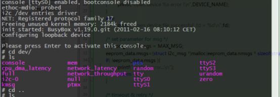
然后在boot linux的过程和进入/dev目录下可以看到i2c bus driver和生成设备文件i2c-x
至此,i2c的总线驱动就添加到内核了。
至于为什么一直强调是i2c的总线驱动呢······再敲代码之前我们先看看csdn上的这两篇blog,看看华清的hongtao_liu老师是怎么说明linux下的I2C。
http://blog.csdn.net/hongtao_liu/article/details/4964244
http://blog.csdn.net/hongtao_liu/article/details/5260739
根据我自己的理解:
1.对于i2c controller来说,编写的驱动程序称为总线驱动,例如上面在or1200_soc中添加的i2c控制器ipcore,为之编写的驱动程序就是总线驱动。
2.对于挂在i2c总线上的slave device来说,为之编写的驱动程序称为设备驱动,例如我板子上挂在这个ipcore上的AT24c08的eeprom。
3.linux下的i2c子系统中还有一个i2c核心模块来为总线驱动和设备驱动服务,完成注册,删除······功能。
现在说明一下:在openrisc-3.1\drivers\i2c\busses目录下的i2c-ocores.c文件为soc上添加的i2c controller提供了总线驱动,即在刚才的内核配置中已经选择编入了内核,所以可以略过总线驱动的编写,在下节我们着重分析这个总线驱动。
现在可以先打开这个文件,里面的comment中就有关于device-tree文件如何加入i2c device描述的说明
- /*
- * Device tree configuration:
- *
- * Required properties:
- * - compatible : "opencores,i2c-ocores"
- * - reg : bus address start and address range size of device
- * - interrupts : interrupt number
- * - regstep : size of device registers in bytes
- * - clock-frequency : frequency of bus clock in Hz
- *
- * Example:
- *
- * i2c0: ocores@a0000000 {
- * compatible = "opencores,i2c-ocores";
- * reg = <0xa0000000 0x8>;
- * interrupts = <10>;
- *
- * regstep = <1>;
- * clock-frequency = <20000000>;
- *
- * -- Devices connected on this I2C bus get
- * -- defined here; address- and size-cells
- * -- apply to these child devices
- *
- * #address-cells = <1>;
- * #size-cells = <0>;
- *
- * dummy@60 {
- * compatible = "dummy";
- * reg = <60>;
- * };
- * };
- *
- */
在openrisc-3.1\drivers\i2c目录下的i2c-dev.c文件中,linux为我们提供了虚拟的统一的设备文件接口,如果我们懒得去编写设备驱动程序时,可以利用这个接口直接在应用层上完成对i2c总线的slave device操作。
所以在这一节当中,我们不编写总线驱动和设备驱动,先运用系统提供的文件接口进行操作,具体的代码主要参考hongtao_liu老师提供的代码。
- #include <stdio.h>
- #include <string.h>
- #include <stdlib.h>
- #include <fcntl.h> // open()
- #include <sys/ioctl.h>
- #include <unistd.h> // read() write() close() usleep()
- #include <linux/types.h>
- #include <linux/i2c.h> // i2c_msg
- #include <linux/i2c-dev.h> // i2c_rdwr_ioctl_data
- #define DEVICE_NAME "/dev/i2c-0"
- #define MAX_MSG 2
- #define EEPROM_ADDR 0x54
- //--------------------------------------------- main -----------------------------------------------------
- int main(){
- int fd;
- int ret;
- struct i2c_rdwr_ioctl_data eeprom_data;
- /* open device file */
- printf("\nstart simple_i2c application test ! \n");
- fd = open(DEVICE_NAME, O_RDWR);
- if (fd == -1){
- printf("open device %s error !\n",DEVICE_NAME);
- }
- else
- printf("open device file successful, fd = %d\n",fd);
- /* set parameter for msg */
- eeprom_data.nmsgs = MAX_MSG;
- eeprom_data.msgs=(struct i2c_msg *)malloc(eeprom_data.nmsgs * sizeof(struct i2c_msg));
- if( !eeprom_data.msgs ){
- printf("malloc error...\n");
- return -1;
- }
- /* timeout & retry */
- ioctl(fd, I2C_TIMEOUT, 1);
- ioctl(fd, I2C_RETRIES, 2);
- /* write data to eeprom */
- eeprom_data.nmsgs = 1;
- (eeprom_data.msgs[0]).len = 2;
- (eeprom_data.msgs[0]).addr = EEPROM_ADDR;
- (eeprom_data.msgs[0]).flags = 0;
- (eeprom_data.msgs[0]).buf = (unsigned char*)malloc(2);
- (eeprom_data.msgs[0]).buf[0] = 0x10;
- (eeprom_data.msgs[0]).buf[1] = 0x50;
- ret = ioctl(fd, I2C_RDWR, (unsigned long)&eeprom_data);
- if(ret < 0){
- printf("ioctl error...\n");
- }
- /* read data from eeprom */
- eeprom_data.nmsgs = 2;
- (eeprom_data.msgs[0]).len = 1;
- (eeprom_data.msgs[0]).addr = EEPROM_ADDR;
- (eeprom_data.msgs[0]).flags = 0;
- (eeprom_data.msgs[0]).buf[0] = 0x10;
- (eeprom_data.msgs[1]).len = 1;
- (eeprom_data.msgs[1]).addr = EEPROM_ADDR;
- (eeprom_data.msgs[1]).flags = I2C_M_RD;
- (eeprom_data.msgs[1]).buf = (unsigned char*)malloc(1);
- (eeprom_data.msgs[1]).buf[0] = 0;
- ret = ioctl(fd, I2C_RDWR, (unsigned long)&eeprom_data);
- if(ret < 0){
- printf("ioctl error...\n");
- }
- printf("buff[0]=%x\n",(eeprom_data.msgs[1]).buf[0]);
- /* close device file */
- ret = close(fd);
- printf ("ret=%d\n",ret);
- printf ("end simple_i2c test...\n");
- /* */
- return 0;
- }
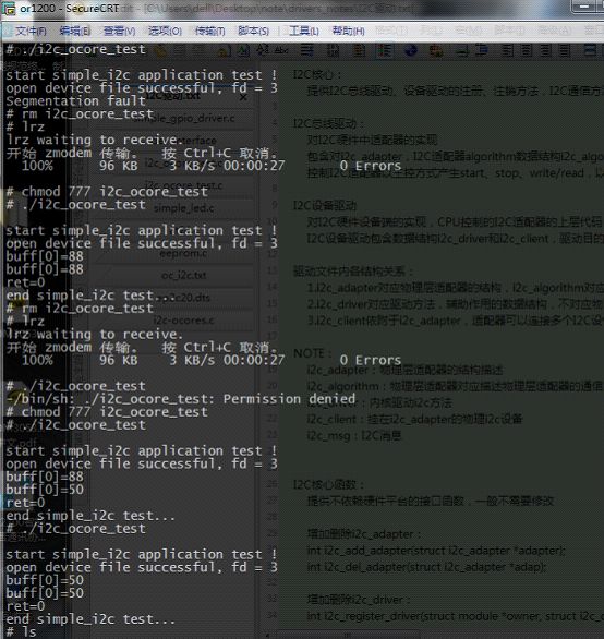
编写完后在虚拟机上编译,老规矩,在板子上lrz后修改文件属性
然后可以多次修改其中写入地址和数据的代码,看看是否能正确读写
至此,有时间修改一下这个测试文件成比较实用的文件,下节对这个ipcore的i2c bus driver的分析,即对openrisc-3.1\drivers\i2c\busses目录下的i2c-ocores.c的总线驱动稍作分析,当是学习如何编写总线驱动。
OK,又一周了,追追动漫去了~,最近手头上有点忙了,苦逼的程序员真是伤不起啊,希望有心力的人接着弄下去吧,下次都不知道什么时候有时间更新这个系列的文章了,但是会写写别的文章~bye~bye


