Copyright © 2003 International Business Machines Corp.

用Draw2D绘制UML图
摘要
图形编辑框架(GEF)运作于Draw2D之上。Draw2D是一个提供绘画和布局管理的插件,为GEF应用程序提供图形以及布局管理器来构建程序 的图形表示层。本文仅着眼于如何使用Draw2D来绘制UML图。Draw2D可以独立使用,然而其并不是一个编辑框架。大多的应用程序会使用GEF插件 实现编辑功能。
介绍
Draw2D提供了在SWT画布上绘画以及布局的轻量级实现。图形(Figure)、布局管理器(Layout Manager),以及边框(Border)可以被任意组合和内嵌来构建复杂的图形来适应任何的应用程序。选择正确的图形组合来创建想要的图形是一件很精 细微妙的工作,本文将指导你如何创建一个复杂的图形。
由于本文的范围所限,本文的示例代码将独立使用Draw2D,但大多数的应用程序会将GEF和Draw2D结合使用。
创建Draw2D图形
示例
下图是一个简单的UML类图,本文建立在创建这个图形的基础之上。
设计图形
创建图形的第一步是确定使用什么组件来合成图形,以及它们是如何排列的。
例图由三个子图形组成。图形本身为UMLClassFigure,它的第一个子图形是Label,用来显示类名(本例为“Table”),另外两个 子图形是用来放置属性及方法的容器。我们将创建一个叫做CompartmentFigure的图形来达到容器的目的。UMLClassFigure和 CompartmentFigure都使用ToolbarLayout来放置子图形,下图是它在概念上的上层结构图:
创建CompartmentFigure类
CompartmentFigure用来放置方法和属性,这个类继承org.eclipse.draw2d.Figure类,并且使用 ToolbarLayout来管理子图形的布局,同时,CompartmentFigure使用了一个自定义的边框。这个边框只是简单的在它的上端画一条 1个象素粗细的线,作为两个CompartmentFigure的分隔。CompartmentFigure的代码如下:
public class CompartmentFigure extends Figure {

  public CompartmentFigure() {
    ToolbarLayout layout = new ToolbarLayout();
    layout.setMinorAlignment(ToolbarLayout.ALIGN_TOPLEFT);
    layout.setStretchMinorAxis(false);
    layout.setSpacing(2);
    setLayoutManager(layout);
    setBorder(new CompartmentFigureBorder());
  }

  public class CompartmentFigureBorder extends AbstractBorder {
    public Insets getInsets(IFigure figure) {
      return new Insets(1,0,0,0);
    }
    public void paint(IFigure figure, Graphics graphics, Insets insets) {
      graphics.drawLine(getPaintRectangle(figure, insets).getTopLeft(),
                        tempRect.getTopRight());
    }
  }
} |
创建UMLClassFigure类
UMLClassFigure类在很多地方都和CompartmentFigure类很相似,它包含三个子图形——用来放置方法和属性的两个 CompartmentFigure和一个用来显示类名的Draw2D标签(Label)。它也使用了垂直导向的ToolbarLayout来管理子图形 的布局。UMLClassFirgure使用Draw2D的LineBorder在自己的边缘绘制矩形边框。
public class UMLClassFigure extends Figure {
  public static Color classColor = new Color(null,255,255,206);
  private CompartmentFigure attributeFigure = new CompartmentFigure();
  private CompartmentFigure methodFigure = new CompartmentFigure();
  public UMLClassFigure(Label name) {
    ToolbarLayout layout = new ToolbarLayout();
    setLayoutManager(layout);
    setBorder(new LineBorder(ColorConstants.black,1));
    setBackgroundColor(classColor);
    setOpaque(true);

    add(name);
    add(attributeFigure);
    add(methodFigure);
  }
  public CompartmentFigure getAttributesCompartment() {
    return attributeFigure;
  }
  public CompartmentFigure getMethodsCompartment() {
    return methodFigure;
  }
} |
增加连接
Draw2D提供了一种成为连接(Connection)特殊的图形,用来连接两个图形。要在Draw2D中创建连接,首先要创建连接的两个端点 (endpoint)。这辆个端点成为源支撑点(source anchor)和目标支撑点(target anchor)。端点由实现了ConnectionAnchor接口的类来创建。在支撑点创建好后,便可通过调用 setSourceAnchor(ConnectionAnchor)方法和setTargetAnchor(ConnectionAnchor)方法来 将其设定为端点。本例使用了称为ChopboxAnchor的支撑点,这种支撑点将端点放置在图形的边缘,并且将方向指向图形的中心。
以下代码增加了一个连接:
PolylineConnection c = new PolylineConnection();
ChopboxAnchor sourceAnchor = new ChopboxAnchor(classFigure);
ChopboxAnchor targetAnchor = new ChopboxAnchor(classFigure2);
c.setSourceAnchor(sourceAnchor);
c.setTargetAnchor(targetAnchor); |

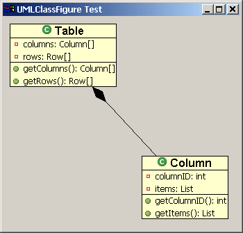
由PolyLineConnection连接的两个UMLClassFirgure
连接的装饰
Draw2d同时也为端点提供了箭头等形状的可以具有一定意义的装饰。和UML一样,我们将创建一个实心的菱形装饰来表示组合关系。这将由 PolygonDecoration来实现。PolygonDecoration的缺省形状是实心箭头,然而可以通过创建新模板来实现任何形状。模板由 PointList定义,通过调用setTemplate(PointList)来指定。
以下代码演示了如何将PolygonDecoration加到连接上去:
PolygonDecoration decoration = new PolygonDecoration();
PointList decorationPointList = new PointList();
decorationPointList.addPoint(0,0);
decorationPointList.addPoint(-2,2);
decorationPointList.addPoint(-4,0);
decorationPointList.addPoint(-2,-2);
decoration.setTemplate(decorationPointList);
c.setSourceDecoration(decoration); |

具有PolygonDecoration的连接
使用Locator给连接加上标签
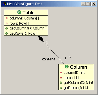
除了装饰之外,我们还可以给连接增加其他的Draw2d图形。这可以通过调用连接的add(IFigure figure, Object constratint)方法实现,其中figure为要增加的图形,constraint是一个实现了Locator接口的类,由Locator将图形 放置在连接上。我们将使用这种技术来为我们的类图加上标签。ConnectionEndpointLocator可以将图形放置在连接的源端点或目标端点 上,因而我们选用它来放置标签。我们还可以通过调用setUDistance(int)和setVDistance(int)方法来指定图形与端点的举例 (其中uDistance是连接的图形到将要加上去的图形的距离,而vDistance则是将要加上的图形到连接本身的举例)。
以下代码演示了如何使用ConnectionEndpointLocator给一个连接加上标签:
ConnectionEndpointLocator targetEndpointLocator =
            new ConnectionEndpointLocator(c, true);
targetEndpointLocator.setVDistance(15);
Label targetMultiplicityLabel = new Label("1..*");
c.add(targetMultiplicityLabel, targetEndpointLocator);
ConnectionEndpointLocator sourceEndpointLocator =
            new ConnectionEndpointLocator(c, false);
sourceEndpointLocator.setVDistance(15);
Label sourceMultiplicityLabel = new Label("1");
c.add(sourceMultiplicityLabel, sourceEndpointLocator);

ConnectionEndpointLocator relationshipLocator =
            new ConnectionEndpointLocator(c,true);
relationshipLocator.setUDistance(30);
relationshipLocator.setVDistance(-20);
Label relationshipLabel = new Label("contains");
c.add(relationshipLabel,relationshipLocator);
|

增加了标签的连接
创建测试类
测试类包含了一个main方法来创建一个含有Draw2d LightweightSystem(LWS,用来连接SWT和Draw2d)的SWT Shell。例子使用Draw2d的Figure类作为LWS的内容,并在Figure上增加了两个UMLClassFigure。然后在两个图形间创建 了一个带有菱形端点装饰和标签的连接。
测试类使用了几个图片{ 

 },请自行下载并放在java工程的根文件夹下。
import org.eclipse.draw2d.*;
import org.eclipse.draw2d.geometry.PointList;
import org.eclipse.draw2d.geometry.Rectangle;
import org.eclipse.swt.SWT;
import org.eclipse.swt.graphics.Font;
import org.eclipse.swt.graphics.Image;
import org.eclipse.swt.widgets.Display;
import org.eclipse.swt.widgets.Shell;

/**
 * A test class to display a UMLFigure
 */
public class UMLClassFigureTest {
 public static void main(String args[]){
	Display d = new Display();
	final Shell shell = new Shell(d);
	shell.setSize(400, 400);
	shell.setText("UMLClassFigure Test");
	LightweightSystem lws = new LightweightSystem(shell);
	Figure contents = new Figure();
	XYLayout contentsLayout = new XYLayout();
	contents.setLayoutManager(contentsLayout);

	Font classFont = new Font(null, "Arial", 12, SWT.BOLD);
	Label classLabel1 = new Label("Table", new Image(d,
		UMLClassFigureTest.class.getResourceAsStream("class_obj.gif")));
	classLabel1.setFont(classFont);

	Label classLabel2 = new Label("Column", new Image(d,
	        UMLClassFigureTest.class.getResourceAsStream("class_obj.gif")));
	classLabel2.setFont(classFont);

	final UMLClassFigure classFigure = new UMLClassFigure(classLabel1);
	final UMLClassFigure classFigure2 = new UMLClassFigure(classLabel2);

	Label attribute1 = new Label("columns: Column[]", new Image(d,
		UMLClassFigure.class.getResourceAsStream("field_private_obj.gif")));
	Label attribute2 = new Label("rows: Row[]", new Image(d,
		UMLClassFigure.class.getResourceAsStream("field_private_obj.gif")));
	Label attribute3 = new Label("columnID: int", new Image(d,
		UMLClassFigure.class.getResourceAsStream("field_private_obj.gif")));
	Label attribute4 = new Label("items: List", new Image(d,
		UMLClassFigure.class.getResourceAsStream("field_private_obj.gif")));

	classFigure.getAttributesCompartment().add(attribute1);
	classFigure.getAttributesCompartment().add(attribute2);
	classFigure2.getAttributesCompartment().add(attribute3);
	classFigure2.getAttributesCompartment().add(attribute4);

	Label method1 = new Label("getColumns(): Column[]", new Image(d,
		UMLClassFigure.class.getResourceAsStream("methpub_obj.gif")));
	Label method2 = new Label("getRows(): Row[]", new Image(d,
		UMLClassFigure.class.getResourceAsStream("methpub_obj.gif")));
	Label method3 = new Label("getColumnID(): int", new Image(d,
		UMLClassFigure.class.getResourceAsStream("methpub_obj.gif")));
	Label method4 = new Label("getItems(): List", new Image(d,
		UMLClassFigure.class.getResourceAsStream("methpub_obj.gif")));

	classFigure.getMethodsCompartment().add(method1);
	classFigure.getMethodsCompartment().add(method2);
	classFigure2.getMethodsCompartment().add(method3);
	classFigure2.getMethodsCompartment().add(method4);

	contentsLayout.setConstraint(classFigure, new Rectangle(10,10,-1,-1));
	contentsLayout.setConstraint(classFigure2, new Rectangle(200, 200, -1, -1));

	/* Creating the connection */
	PolylineConnection c = new PolylineConnection();
	ChopboxAnchor sourceAnchor = new ChopboxAnchor(classFigure);
	ChopboxAnchor targetAnchor = new ChopboxAnchor(classFigure2);
	c.setSourceAnchor(sourceAnchor);
	c.setTargetAnchor(targetAnchor);

	/* Creating the decoration */
	PolygonDecoration decoration = new PolygonDecoration();
	PointList decorationPointList = new PointList();
	decorationPointList.addPoint(0,0);
	decorationPointList.addPoint(-2,2);
	decorationPointList.addPoint(-4,0);
	decorationPointList.addPoint(-2,-2);
	decoration.setTemplate(decorationPointList);
	c.setSourceDecoration(decoration);

	/* Adding labels to the connection */
	ConnectionEndpointLocator targetEndpointLocator =
	        new ConnectionEndpointLocator(c, true);
	targetEndpointLocator.setVDistance(15);
	Label targetMultiplicityLabel = new Label("1..*");
	c.add(targetMultiplicityLabel, targetEndpointLocator);

	ConnectionEndpointLocator sourceEndpointLocator =
		new ConnectionEndpointLocator(c, false);
	sourceEndpointLocator.setVDistance(15);
	Label sourceMultiplicityLabel = new Label("1");
	c.add(sourceMultiplicityLabel, sourceEndpointLocator);

	ConnectionEndpointLocator relationshipLocator =
		new ConnectionEndpointLocator(c,true);
	relationshipLocator.setUDistance(10);
	relationshipLocator.setVDistance(-20);
	Label relationshipLabel = new Label("contains");
	c.add(relationshipLabel,relationshipLocator);

	contents.add(classFigure);
	contents.add(classFigure2);
	contents.add(c);

	lws.setContents(contents);
	shell.open();
	while (!shell.isDisposed())
		while (!d.readAndDispatch())
			d.sleep();
 }
} |
结论
本文介绍了使用Graphical Editing Framework的可视化组件——Draw2d图形——的使用,同时也介绍了Draw2d连接、装饰、locator的概念。更多的信息请访问GEF主页(http://www.eclipse.org/gef)
![]()
![]()
![]() },请自行下载并放在java工程的根文件夹下。
},请自行下载并放在java工程的根文件夹下。


