- Linux系统网络配置与Bond多网卡绑定
zai.zai
linux运维服务器
目录一、查看网络配置命令1.1、ifconfig1.2、ip1.3、hostname1.4、route1.5、netstat1.6、ss1.7、ping1.8、traceroute1.9、nslookup二、永久修改网络配置2.1、网络接口配置文件3.1、主机名配置文件三、Bonding多网卡绑定3.1、bondding工作模式3.2、配置bond3.2.1、添加网卡3.2.2、新建bond配置文
- VM虚拟机+Ubuntu系统NAT网络配置
问道飞鱼
后端开发技术实践计算机相关知识科普付费专栏ubuntulinux运维
一、VM虚拟网络配置配置入口:编辑->虚机网络编辑器(不要开启“使用本地的DHCP服务”,会造成虚拟机一旦关闭重启,IP就会发生变化,不是我们希望看到的)点开NAT设置虚拟机配置如下:二、本地操作系统网络配置找到虚拟网卡配置静态地址
- c高级终端指令
zm
php开发语言
复习命令行提示符:显示当前用户、计算机名、当前路径和用户权限。切换用户:使用su用户名切换用户,sudopasswd用户名修改用户密码。文件操作命令:cd用于切换目录,ls列出文件和目录,mv移动或重命名文件,cp复制文件,cat查看文件内容,touch创建或更新文件时间戳。网络配置虚拟网络模式:桥接模式下虚拟机和主机可网络通信且IP不同;主机模式只能与主机通信;NAT模式外部看到主机和虚拟机IP
- Linux入门的基础知识点汇总(带示例)
浪九天
操作系統linuxubuntu
目录文件和目录操作文本处理命令系统管理命令用户和权限管理权限管理软件安装与管理网络配置Linux是一种广泛使用的开源操作系统,对于初学者而言,掌握一些基础知识点十分关键。以下为你详细介绍:文件和目录操作ls:用于列出目录内容。-a选项可显示所有文件和目录,包含隐藏文件,比如ls-a就能看到当前目录下以.开头的隐藏文件。-l选项是以长格式显示详细信息,像文件权限、所有者、大小、修改时间等,ls-l会
- Linux (deepin)网络管理详解.
liguangxian2018
Linuxlinuxdeepin网络
网络管理编辑历史版本English前言本条目简单介绍Linux下的网络管理,包含网络配置文件和网络管理命令。网络配置文件关于网络的配置文件有:主机地址配置文件:/etc/hosts网络服务信息文件:/etc/services允许与拒绝地址配置文件:/etc/hosts.allow和/etc/hosts.deny网络配置文件:/etc/network/interfaces主机查找配置文件:/etc/
- 长效静态IP为什么持久稳定的奥秘?
ip地址动态代理代理服务器
在数字化世界中,网络连接的稳定性和可靠性至关重要。长效静态IP地址作为一种网络配置方式,以其持久稳定的特性受到了广大用户的青睐。长效静态IP之所以持久稳定,其奥秘主要源于以下几个方面:静态特性静态IP地址不会频繁更改,这意味着一旦分配给某个设备或网络,它就会保持不变。这种稳定性使得网络管理员可以更容易地配置和管理网络,因为无需经常更新IP地址信息。可预测性由于静态IP地址不会改变,因此可以预测其行
- Docker安装Centos
卑微的小鬼
dockercentos容器
第一步:安装镜像启动之后,修改网络配置echo“nameserver8.8.8.8”>/etc/resolv.confecho“nameserver1.1.1.1”>>/etc/resolv.conf第二步:修改镜像源配置/etc/yum.repos.d涉及三个文件可以提前做好备份(1)CentOS-Linux-AppStream.repo(2)CentOS-Linux-Extras.repo(3
- Linux学习笔记 - 6
Norvyn_7
Linux学习linux学习笔记
Linux学习笔记-6本篇将介绍网络配置、传输工具、端口管理、进程管理、主机监控及环境变量相关命令。1.IP地址和主机名1.1IP地址作用:用于计算机之间的网络通信。IPv4格式:a.b.c.d(每个数字范围0~255),例如192.168.1.1。查看本机IP:ifconfig#需先安装net-toolsipaddr#无需安装,推荐使用安装ifconfig:CentOS:yum-yinstall
- 【虚拟机网络】虚拟机的网络配置教程,亲测有效!
2022lcl
网络
一、环境准备虚拟机软件:VMwareWorkstation17操作系统:CentOS7/Ubuntu22.04网络模式:NAT模式(VMnet8)二、配置虚拟网络编辑器1.启用VMnet8打开VMware,进入编辑>虚拟网络编辑器。选择VMnet8,勾选NAT模式,点击确定保存。2.设置默认网关和静态ip池点击更改设置获取管理员权限。进入NAT设置,填写默认网关(例如192.168.177.2)。
- 容器docker k8s相关的问题汇总及排错
weixin_43806846
dockerkubernetes容器
1.明确问题2.排查方向2.1、docker方面dockerlogs-f容器IDdocker的网络配置问题。2.2、k8s方面node组件问题pod的问题(方式kubectldescribepopod的名称-n命名空间&&kubectllogs-fpod的名称-n命名空间)调度的问题(污点、节点选择器与标签不匹配、存储卷的问题)service问题(访问不了,ingress的问题、service标签
- Dify实现text2sql工作流[SQL调用篇],并查询Postgres数据库 or Mysql数据库(docker容器)
汀、人工智能
LLM工业级落地实践sqlmysqlNL2SQLtext2sqlDify
Dify实现text2sql,查询Postgres数据库1.Postgres数据库设置1.1.docker-compose.yml修改为了让sandbox容器能够与docker-db-1容器互相通信,你需要确保几个条件得到满足:网络配置:确保sandbox和db都位于同一个Docker网络中。如果它们不在同一个网络中,数据包将无法直接在容器间路由。从你提供的配置来看,sandbox已经定义了一个网
- CentOS 8 配置bond
清风 001
AI大模型底层建设网络
CentOS8网络配置的详细步骤和对应的配置文件内容。1.配置聚合网卡(Bonding)配置intranet聚合网卡在/etc/sysconfig/network-scripts/目录下创建ifcfg-intranet文件,内容如下:TYPE=BondNAME=intranetDEVICE=intranetONBOOT=yesBOOTPROTO=noneIPADDR=10.2.1.22PREFIX
- Java永久性修改Linux(Debian/Ubuntu)网络
久违放晴
linuxjavadebianubuntu网络
文章目录前言一、实现思路二、手动配置网络(一)编辑/etc/network/interfaces文件(二)重启网络(三)查看网络配置三、shell脚本配置网络(一)脚本执行流程(二)编写脚本(三)完整代码(四)脚本执行方式(五)直接覆盖版(六)使用工具包的实现方案四、通过Java调用shell脚本(一)SSH远程连接调用(二)使用本地指令调用的方案总结前言对于一些私有化部署的系统,部署完毕后经常需
- Linux操作系统:网络配置与系统监控优化
暮雨哀尘
Linux的那点事开发语言linux网络运维系统架构服务器防火墙
摘要在当今数字化时代,Linux系统作为服务器和网络设备的核心,其网络配置和系统监控优化能力至关重要。本文以幽默风趣的笔触,深入探讨了Linux网络配置、防火墙设置、系统监控以及性能优化的关键技术。通过实例和表格,展示了如何在Linux环境中实现高效、稳定的网络服务和系统性能。无论是初学者还是资深管理员,都能从本文中找到实用的知识和技巧,让Linux系统在复杂多变的网络环境中游刃有余。关键词Lin
- 红队内网攻防渗透:内网渗透之Windows内网信息收集:内网和域
HACKNOE
红队攻防内网渗透研究院web安全网络安全系统安全
红队内网攻防渗透1.内网渗透之信息收集1.内网信息收集的目的2.本机信息收集网络配置查询操作系统及版本信息查看系统体系结构查看安装的软件及版本、路径等查询本机服务查询进程列表查毒软件查看启动程序信息查看计划任务查看主机开机时间查询用户列表获取本地管理员查看当前在线用户列出或断开本地计算机与所连的客户端之间的会话查看端口列表查看补丁列表查看共享连接保存当前主机上的所有WiFi信息查看本机共享列表查询
- 在Linux系统上使用nmcli命令配置各种网络(有线、无线、vlan、vxlan、路由、网桥等)
web13508588635
linux网络服务器
1、更新于2024/5/13,新增VethPair配置2、更新于2024/5/19,修复NetworkManager接管网络配置无效的错误3、更新于2024/5/20,新增Ubuntu两种版本下NetworkManager接管网络的配置目录一、配置NetworkManager接管网络(选)安装Network-Manager并启动netplan管理网络的系统ifupdown管理网络的系统二、nmcl
- 2025超全整理!H3C路由交换核心命令宝典,助你轻松玩转网络配置
wljslmz
网络技术H3C路由器交换机命令大全
H3C(新华三)作为国内网络设备的领军品牌,其路由器和交换机广泛应用于企业、数据中心及运营商网络。掌握H3C设备的配置命令,是网络工程师的必备技能!本文结合2025年最新技术文档与实战经验,系统梳理基础配置、VLAN管理、路由协议、IRF堆叠、安全加固等场景的核心命令,助你从“小白”进阶为“大神”!文末还附赠高频踩坑指南,速速收藏⭐!一、基础配置篇:快速上手H3C设备1.设备初始化与视图切换进入系
- PVE 网络配置详解:双网卡聚合与 Linux 网络管理技巧
The god of big data
虚拟系统神器?三叉戟?教程网络linux运维
ProxmoxVE(PVE)作为基于Linux的虚拟化平台,其网络配置逻辑与Windows存在显著差异,尤其在多网卡管理、链路聚合(Bonding)等方面。本文将以双网卡聚合为核心,详解PVE的网络配置方法,并对比Windows帮助用户快速上手。一、Linux与Windows网络配置的核心区别1.网卡命名规则Windows:网卡名称为“以太网”“本地连接”等,可自定义。PVE(Linux):网卡默
- Ubuntu22.04系统安装及配置
乌托邦的逃亡者
Ubuntulinux运维服务器ubuntu
文章目录一、选择“安装”二、选择“语言”三、安装器更新四、键盘布局五、选择安装类型六、网络配置七、代理设置八、镜像地址九、磁盘划分十、设置用户名、主机名、登录密码十一、升级到UbuntuPro十二、SSH设置十三、选装软件包十四、开始安装进程十五、配置静态IP十六、设置时区十七、包管理工具十八、防火墙设置十九、修改linux参数(调大最大文件句柄数)二十、如何使用root账号二十一、安装JDK二十
- 如何在 Linux 中查找默认网关 IP?
wljslmz
Linux技术默认网关
在计算机网络中,默认网关(DefaultGateway)是一个关键的网络设备,通常是路由器或防火墙,它负责将数据包从本地网络转发到其他网络。对于Linux系统用户来说,了解如何查找默认网关的IP地址是非常重要的,尤其是在进行网络配置、故障排除或安全审计时。在深入探讨如何查找默认网关之前,首先需要理解什么是默认网关以及它在网络中的作用。默认网关是网络中用于转发数据包到其他网络的设备。当一台计算机需要
- 编写Linux系统rhel9的网络配置脚本
Bug.ink
linux运维服务器
要求:名称:vmset.sh操作:vmset.sh后加网卡名,ip即可配置好网卡的IP操作:在/bin路径下编写脚本vmset.sh,可以直接执行,不用加其他路径vim/bin/vmset.sh#!/bin/bashinterface_name=$1ip_address=$2cat>/etc/NetworkManager/system-connections/${interface_name}.n
- 【云原生技术】 YAML 配置管理、部署架构和灾备方案三个方面介绍一下如何在上海浦东新区和松江两个机房间实现容器部署和容灾
阿寻寻
云原生技术云原生架构
云部署灾备一、YAML配置管理二、部署架构和灾备策略三、故障场景下的应急预案四、总结一、YAML配置管理在实际生产环境中,为了达到高可用、快速灾备的目标,通常需要在YAML配置管理和部署架构上都做出专门设计。下面我从YAML配置管理、部署架构和灾备方案三个方面介绍一下如何在上海A区和B区两个机房间实现容器部署和容灾。【1.YAML配置管理】由于两个机房可能在硬件选型(如存储类、节点标签、网络配置)
- 【Linux-常用命令】Linux 常用命令大全
bmyyyyyy
开发语言linux运维服务器
【Linux-常用命令】Linux常用命令大全1)文件管理1.1.目录操作1.2.vim操作1.3.打包压缩相关命令1.4.Linux管道1.5.Linux远程拷贝命令1.6.查看文件目录大小2)文件权限管理2.1.三种基本权限2.2.更改权限3)运行程序3.1.命令行运行3.2.后台运行3.3.服务方式运行4)系统相关4.1.系统管理命令4.2.防火墙4.3.关机和重启4.4.网络配置5)用户管
- Centos10 Stream 基础配置
Tyran_U
Linuxlinux
NetworkManger安装dnfinstallNetworkManager查看网络配置nmcli[root@Centos-S-10/]#nmcliens33:已连接到ens33"Intel82545EM"ethernet(e1000),00:0C:29:08:3E:71,硬件,mtu1500ip4默认inet4192.168.31.70/24route4defaultvia192.168.31
- AI应用完整加载数据集配置神经网络配置训练信息训练模型与保存模型到本地------AI
旧约Alatus
AI软件架构设计人工智能stablediffusionchatgptAIGCDALL·E2AI-nativebard
packagecom.alatus.djl.web;importai.djl.Application;importai.djl.MalformedModelException;importai.djl.Model;importai.djl.basicdataset.cv.classification.ImageFolder;importai.djl.basicdataset.cv.classifi
- 将Hyper-V虚拟机与主机共享网络
qq_58647543
网络
Hyper-V网络设置目标将Hyper-V虚拟机网络配置为与主机使用同一网络,并确保主机网络与虚拟机网络连接互不受影响。前提条件主机上已安装Hyper-V已创建Hyper-V虚拟机步骤1.配置主机网络共享打开控制面板->网络和Internet->网络连接。右键点击WIAN,选择“属性”。切换到“共享”选项卡。勾选“允许其他网络用户通过此计算机的Internet连接进行连接”。在“家庭网络连接”下拉
- 详解 127.0.0.1 和 0.0.0.0 的区别与用法
咖啡虫
项目开发中配置文件或环境文件macos
详解127.0.0.1和0.0.0.0的区别与用法在网络配置和系统开发中,127.0.0.1和0.0.0.0是两个经常出现的IP地址。虽然它们表面相似,但在功能和应用场景上有显著区别。本文将详细介绍它们的含义、区别以及常见用法。1.什么是127.0.0.1?127.0.0.1通常被称为回环地址(LoopbackAddress),也被称为localhost。它的主要作用是将网络请求重定向到本地计算机
- OpenStack-Train版-Allinone自动化部署脚本
编程就是如此
OpenStackopenstack自动化运维
一、环境准备操作系统:CentOS7或以上版本建议配置:CPU:8核或以上内存:16GB或以上磁盘:500GB或以上网络配置:确保虚拟机已配置静态IP地址确保虚拟机可以正常访问外部网络二、自动化部署脚本#!/bin/bash#设置主机名hostnamectlset-hostnameopenstack.alione.localecho"Hostnamesettoopenstack.alione.lo
- 镜像网络模式配置WSL2——完美解决wsl2无法ping宿主机,也无法ping外网的问题
友恒
网络linux
完美解决wsl2无法ping宿主机,也无法ping外网的问题背景:wsl2通过NAT方式与宿主机共享网络,这就导致wsl2的网络需要经过一些配置才能访问外网,尤其是涉及到梯子时。为了避免各种麻烦的网络配置问题,建议使用镜像网络模式配置wsl2。本文介绍如何使用镜像模式配置WSL2。前提条件:宿主机可以上网宿主机打开了对WSL2的防火墙设置。(可参考其它文章)下面是将WSL2配置成镜像模式的步骤。1
- 网络安全知识|网安问答题|OSPF报文协议|抓包工具|路由器环路|序列化与反序列化|磁盘利用率|网络攻防
Red Red
计算机网络网络web安全笔记学习秋招求职招聘安全
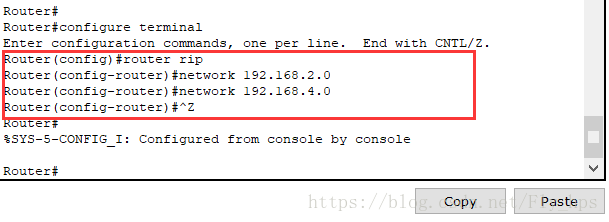
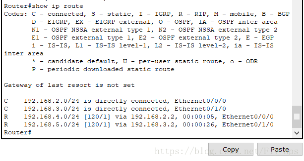
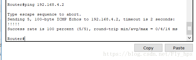
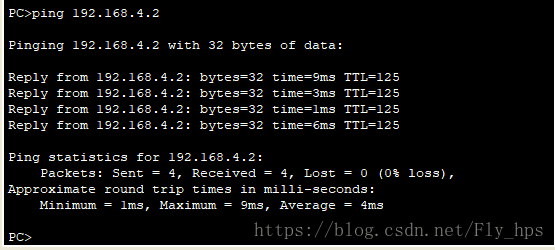
网络安全知识|网安问答题|OSPF报文协议|抓包工具|路由器环路|序列化与反序列化|磁盘利用率|网络攻防作为网络工程师,怎么处理防火墙没网的问题?检查防火墙规则:确保防火墙规则没有错误地阻止了网络访问。需要检查防火墙设置,特别是入站和出站规则,确保允许了必要的端口和服务。例如,如果需要访问互联网,确保防火墙允许了HTTP(80端口)和HTTPS(443端口)等协议的流量确认网络配置:检查设备的IP
- ViewController添加button按钮解析。(翻译)
张亚雄
c
<div class="it610-blog-content-contain" style="font-size: 14px"></div>// ViewController.m
// Reservation software
//
// Created by 张亚雄 on 15/6/2.
- mongoDB 简单的增删改查
开窍的石头
mongodb
在上一篇文章中我们已经讲了mongodb怎么安装和数据库/表的创建。在这里我们讲mongoDB的数据库操作
在mongo中对于不存在的表当你用db.表名 他会自动统计
下边用到的user是表明,db代表的是数据库
添加(insert):
- log4j配置
0624chenhong
log4j
1) 新建java项目
2) 导入jar包,项目右击,properties—java build path—libraries—Add External jar,加入log4j.jar包。
3) 新建一个类com.hand.Log4jTest
package com.hand;
import org.apache.log4j.Logger;
public class
- 多点触摸(图片缩放为例)
不懂事的小屁孩
多点触摸
多点触摸的事件跟单点是大同小异的,上个图片缩放的代码,供大家参考一下
import android.app.Activity;
import android.os.Bundle;
import android.view.MotionEvent;
import android.view.View;
import android.view.View.OnTouchListener
- 有关浏览器窗口宽度高度几个值的解析
换个号韩国红果果
JavaScripthtml
1 元素的 offsetWidth 包括border padding content 整体的宽度。
clientWidth 只包括内容区 padding 不包括border。
clientLeft = offsetWidth -clientWidth 即这个元素border的值
offsetLeft 若无已定位的包裹元素
- 数据库产品巡礼:IBM DB2概览
蓝儿唯美
db2
IBM DB2是一个支持了NoSQL功能的关系数据库管理系统,其包含了对XML,图像存储和Java脚本对象表示(JSON)的支持。DB2可被各种类型的企 业使用,它提供了一个数据平台,同时支持事务和分析操作,通过提供持续的数据流来保持事务工作流和分析操作的高效性。 DB2支持的操作系统
DB2可应用于以下三个主要的平台:
工作站,DB2可在Linus、Unix、Windo
- java笔记5
a-john
java
控制执行流程:
1,true和false
利用条件表达式的真或假来决定执行路径。例:(a==b)。它利用条件操作符“==”来判断a值是否等于b值,返回true或false。java不允许我们将一个数字作为布尔值使用,虽然这在C和C++里是允许的。如果想在布尔测试中使用一个非布尔值,那么首先必须用一个条件表达式将其转化成布尔值,例如if(a!=0)。
2,if-els
- Web开发常用手册汇总
aijuans
PHP
一门技术,如果没有好的参考手册指导,很难普及大众。这其实就是为什么很多技术,非常好,却得不到普遍运用的原因。
正如我们学习一门技术,过程大概是这个样子:
①我们日常工作中,遇到了问题,困难。寻找解决方案,即寻找新的技术;
②为什么要学习这门技术?这门技术是不是很好的解决了我们遇到的难题,困惑。这个问题,非常重要,我们不是为了学习技术而学习技术,而是为了更好的处理我们遇到的问题,才需要学习新的
- 今天帮助人解决的一个sql问题
asialee
sql
今天有个人问了一个问题,如下:
type AD value
A
- 意图对象传递数据
百合不是茶
android意图IntentBundle对象数据的传递
学习意图将数据传递给目标活动; 初学者需要好好研究的
1,将下面的代码添加到main.xml中
<?xml version="1.0" encoding="utf-8"?>
<LinearLayout xmlns:android="http:/
- oracle查询锁表解锁语句
bijian1013
oracleobjectsessionkill
一.查询锁定的表
如下语句,都可以查询锁定的表
语句一:
select a.sid,
a.serial#,
p.spid,
c.object_name,
b.session_id,
b.oracle_username,
b.os_user_name
from v$process p, v$s
- mac osx 10.10 下安装 mysql 5.6 二进制文件[tar.gz]
征客丶
mysqlosx
场景:在 mac osx 10.10 下安装 mysql 5.6 的二进制文件。
环境:mac osx 10.10、mysql 5.6 的二进制文件
步骤:[所有目录请从根“/”目录开始取,以免层级弄错导致找不到目录]
1、下载 mysql 5.6 的二进制文件,下载目录下面称之为 mysql5.6SourceDir;
下载地址:http://dev.mysql.com/downl
- 分布式系统与框架
bit1129
分布式
RPC框架 Dubbo
什么是Dubbo
Dubbo是一个分布式服务框架,致力于提供高性能和透明化的RPC远程服务调用方案,以及SOA服务治理方案。其核心部分包含: 远程通讯: 提供对多种基于长连接的NIO框架抽象封装,包括多种线程模型,序列化,以及“请求-响应”模式的信息交换方式。 集群容错: 提供基于接
- 那些令人蛋痛的专业术语
白糖_
springWebSSOIOC
spring
【控制反转(IOC)/依赖注入(DI)】:
由容器控制程序之间的关系,而非传统实现中,由程序代码直接操控。这也就是所谓“控制反转”的概念所在:控制权由应用代码中转到了外部容器,控制权的转移,是所谓反转。
简单的说:对象的创建又容器(比如spring容器)来执行,程序里不直接new对象。
Web
【单点登录(SSO)】:SSO的定义是在多个应用系统中,用户
- 《给大忙人看的java8》摘抄
braveCS
java8
函数式接口:只包含一个抽象方法的接口
lambda表达式:是一段可以传递的代码
你最好将一个lambda表达式想象成一个函数,而不是一个对象,并记住它可以被转换为一个函数式接口。
事实上,函数式接口的转换是你在Java中使用lambda表达式能做的唯一一件事。
方法引用:又是要传递给其他代码的操作已经有实现的方法了,这时可以使
- 编程之美-计算字符串的相似度
bylijinnan
java算法编程之美
public class StringDistance {
/**
* 编程之美 计算字符串的相似度
* 我们定义一套操作方法来把两个不相同的字符串变得相同,具体的操作方法为:
* 1.修改一个字符(如把“a”替换为“b”);
* 2.增加一个字符(如把“abdd”变为“aebdd”);
* 3.删除一个字符(如把“travelling”变为“trav
- 上传、下载压缩图片
chengxuyuancsdn
下载
/**
*
* @param uploadImage --本地路径(tomacat路径)
* @param serverDir --服务器路径
* @param imageType --文件或图片类型
* 此方法可以上传文件或图片.txt,.jpg,.gif等
*/
public void upload(String uploadImage,Str
- bellman-ford(贝尔曼-福特)算法
comsci
算法F#
Bellman-Ford算法(根据发明者 Richard Bellman 和 Lester Ford 命名)是求解单源最短路径问题的一种算法。单源点的最短路径问题是指:给定一个加权有向图G和源点s,对于图G中的任意一点v,求从s到v的最短路径。有时候这种算法也被称为 Moore-Bellman-Ford 算法,因为 Edward F. Moore zu 也为这个算法的发展做出了贡献。
与迪科
- oracle ASM中ASM_POWER_LIMIT参数
daizj
ASMoracleASM_POWER_LIMIT磁盘平衡
ASM_POWER_LIMIT
该初始化参数用于指定ASM例程平衡磁盘所用的最大权值,其数值范围为0~11,默认值为1。该初始化参数是动态参数,可以使用ALTER SESSION或ALTER SYSTEM命令进行修改。示例如下:
SQL>ALTER SESSION SET Asm_power_limit=2;
- 高级排序:快速排序
dieslrae
快速排序
public void quickSort(int[] array){
this.quickSort(array, 0, array.length - 1);
}
public void quickSort(int[] array,int left,int right){
if(right - left <= 0
- C语言学习六指针_何谓变量的地址 一个指针变量到底占几个字节
dcj3sjt126com
C语言
# include <stdio.h>
int main(void)
{
/*
1、一个变量的地址只用第一个字节表示
2、虽然他只使用了第一个字节表示,但是他本身指针变量类型就可以确定出他指向的指针变量占几个字节了
3、他都只存了第一个字节地址,为什么只需要存一个字节的地址,却占了4个字节,虽然只有一个字节,
但是这些字节比较多,所以编号就比较大,
- phpize使用方法
dcj3sjt126com
PHP
phpize是用来扩展php扩展模块的,通过phpize可以建立php的外挂模块,下面介绍一个它的使用方法,需要的朋友可以参考下
安装(fastcgi模式)的时候,常常有这样一句命令:
代码如下:
/usr/local/webserver/php/bin/phpize
一、phpize是干嘛的?
phpize是什么?
phpize是用来扩展php扩展模块的,通过phpi
- Java虚拟机学习 - 对象引用强度
shuizhaosi888
JAVA虚拟机
本文原文链接:http://blog.csdn.net/java2000_wl/article/details/8090276 转载请注明出处!
无论是通过计数算法判断对象的引用数量,还是通过根搜索算法判断对象引用链是否可达,判定对象是否存活都与“引用”相关。
引用主要分为 :强引用(Strong Reference)、软引用(Soft Reference)、弱引用(Wea
- .NET Framework 3.5 Service Pack 1(完整软件包)下载地址
happyqing
.net下载framework
Microsoft .NET Framework 3.5 Service Pack 1(完整软件包)
http://www.microsoft.com/zh-cn/download/details.aspx?id=25150
Microsoft .NET Framework 3.5 Service Pack 1 是一个累积更新,包含很多基于 .NET Framewo
- JAVA定时器的使用
jingjing0907
javatimer线程定时器
1、在应用开发中,经常需要一些周期性的操作,比如每5分钟执行某一操作等。
对于这样的操作最方便、高效的实现方式就是使用java.util.Timer工具类。
privatejava.util.Timer timer;
timer = newTimer(true);
timer.schedule(
newjava.util.TimerTask() { public void run()
- Webbench
流浪鱼
webbench
首页下载地址 http://home.tiscali.cz/~cz210552/webbench.html
Webbench是知名的网站压力测试工具,它是由Lionbridge公司(http://www.lionbridge.com)开发。
Webbench能测试处在相同硬件上,不同服务的性能以及不同硬件上同一个服务的运行状况。webbench的标准测试可以向我们展示服务器的两项内容:每秒钟相
- 第11章 动画效果(中)
onestopweb
动画
index.html
<!DOCTYPE html PUBLIC "-//W3C//DTD XHTML 1.0 Transitional//EN" "http://www.w3.org/TR/xhtml1/DTD/xhtml1-transitional.dtd">
<html xmlns="http://www.w3.org/
- windows下制作bat启动脚本.
sanyecao2314
javacmd脚本bat
java -classpath C:\dwjj\commons-dbcp.jar;C:\dwjj\commons-pool.jar;C:\dwjj\log4j-1.2.16.jar;C:\dwjj\poi-3.9-20121203.jar;C:\dwjj\sqljdbc4.jar;C:\dwjj\voucherimp.jar com.citsamex.core.startup.MainStart
- Java进行RSA加解密的例子
tomcat_oracle
java
加密是保证数据安全的手段之一。加密是将纯文本数据转换为难以理解的密文;解密是将密文转换回纯文本。 数据的加解密属于密码学的范畴。通常,加密和解密都需要使用一些秘密信息,这些秘密信息叫做密钥,将纯文本转为密文或者转回的时候都要用到这些密钥。 对称加密指的是发送者和接收者共用同一个密钥的加解密方法。 非对称加密(又称公钥加密)指的是需要一个私有密钥一个公开密钥,两个不同的密钥的
- Android_ViewStub
阿尔萨斯
ViewStub
public final class ViewStub extends View
java.lang.Object
android.view.View
android.view.ViewStub
类摘要: ViewStub 是一个隐藏的,不占用内存空间的视图对象,它可以在运行时延迟加载布局资源文件。当 ViewSt