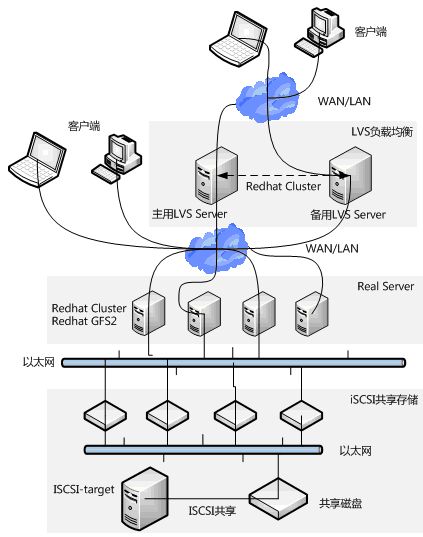
架构拓扑(图片摘自网络)
一、实验环境
os:RedHat 6.4
node5 192.168.2.200 luci管理端
node1 192.168.2.103 集群节点
node2 192.168.2.111 集群节点
虚拟IP 192.168.2.110
初始化操作:关闭所有涉及设备的iptables、selinux=disabled、关闭NetworkManager
注:在该步骤中node2.example.com对应上面环境中提到的node1。node3.example.com对应上面环境中提到的node2。192.168.2.121对应上面环境中提到的192.168.2.200.(由于实验是通过几次完成的,期间涉及到实验环境重置)
二、安装配置
2.1)配置YUM仓库
将系统ISO挂载到本地目录下,然后更改YUM配置文件。最终YUM仓库如下(node1/2配置与node5相同):
[[email protected]]# cat rhel-source.repo
[rhel-source]
name=RedHat Enterprise Linux $releasever - $basearch - Source
baseurl=file:///media/
enabled=1
gpgcheck=0
gpgkey=file:///etc/pki/rpm-gpg/RPM-GPG-KEY-redhat-release
[server]
name=RedHat Enterprise Linux $releasever - $basearch - Source
baseurl=file:///media/Server/
enabled=1
gpgcheck=0
gpgkey=file:///etc/pki/rpm-gpg/RPM-GPG-KEY-redhat-release
[HighAvailability]
name=RedHat Enterprise Linux $releasever - $basearch - Source
baseurl=file:///media/HighAvailability/
enabled=1
gpgcheck=0
gpgkey=file:///etc/pki/rpm-gpg/RPM-GPG-KEY-redhat-release
[LoadBalancer]
name=RedHat Enterprise Linux $releasever - $basearch - Source
baseurl=file:///media/LoadBalancer/
enabled=1
gpgcheck=0
gpgkey=file:///etc/pki/rpm-gpg/RPM-GPG-KEY-redhat-release
[ScalableFileSystem]
name=Red HatEnterprise Linux $releasever - $basearch - Source
baseurl=file:///media/ScalableFileSystem/
enabled=1
gpgcheck=0
gpgkey=file:///etc/pki/rpm-gpg/RPM-GPG-KEY-redhat-release
[ResilientStorage]
name=RedHat Enterprise Linux $releasever - $basearch - Source
baseurl=file:///media/ResilientStorage/
enabled=1
gpgcheck=0
gpgkey=file:///etc/pki/rpm-gpg/RPM-GPG-KEY-redhat-release
2.2)软件安装
node5:
安装scsi-target-utils、luci
node1、node2
安装iscsi-initiator-utils、ricci、cman、lvm2-cluster、gfs2-utils、rgmanager、httpd,部分软件包在安装以上包的同时会依赖安装。
2.3)配置ISCSI Server
将node5上待用作共享存储的硬盘通过fdisk命令划分区,然后在创建LV创建逻辑卷(也可以直接将磁盘共享给节点,多种方式自行选择。此环境中选择将这个磁盘共享给节点)。
2.3.1)配置target
iSCSI target的名称规则:iqn.年份-月份.域名反写.设备识别。
示例:iqn = iSCSI Qualified Name iqn.2014-07.dev.iscsi-target:iscsidisk
target的主要配置文件位于:/etc/tgt/ targets.conf
配置文件详情如下:
# This is a sample config file fortgt-admin.
# By default, tgt-admin looks for itsconfig file in /etc/tgt/targets.conf
#
# The "#" symbol disables theprocessing of a line.
……
backing-store /dev/sdb
通过配置文件可以看出iscsi可以通过多种方式进行共享给相关主机。同时可以限定能访问到该逻辑卷的主机。
2.3.2)启动iscsi服务
#/etc/init.d/tgtd start
#chkconfig tgtd on
2.3.3)查看iscsi target共享状态
[root@node5 ~]# tgt-admin --show
Target 1: iqn.2017-6.com.example:node5
System information:
Driver: iscsi
State: ready
I_T nexus information:
LUN information:
LUN: 0
Type: controller
SCSI ID: IET 00010000
SCSI SN: beaf10
Size: 0 MB, Block size: 1
Online: Yes
Removable media: No
Prevent removal: No
Readonly: No
Backing store type: null
Backing store path: None
Backing store flags:
LUN: 1
Type: disk
SCSI ID: IET 00010001
SCSI SN: beaf11
Size: 21475 MB, Block size: 512
Online: Yes
Removable media: No
Prevent removal: No
Readonly: No
Backing store type: rdwr
Backing store path: /dev/sdb
Backing store flags:
Account information:
ACL information:
ALL
2.4)配置ISCSI Client
2.4.1)设置开机自启动
#chkconfig iscsid on
#chkconfig iscsi on
2.4.2)更改配置文件
initiator的配置文档位于/etc/iscsi/,该目录下有两个文件initiatorname.iscsi和iscsid.conf,其中iscsid.conf 是其配置文件,initiatorname.iscsi 是标记initiator的名称(默认在该文件下有标注iscsi target服务器的iqn号码,将iqn号码更改为自己定义的号码),因为在target里面,我们并没有设置访问限制,所以iscsid.conf 文件并不需要修改。
2.4.3)侦测target
[root@node1 ~]# iscsiadm -m discovery -tsendtargets -p 192.168.2.200
192.168.2.200:3260,1iqn.2017-06.com.example:node5
2.4.4)查看节点
iscsiadm 侦测到的结果会写入/var/lib/iscsi/nodes/中,因此只需启动/etc/init.d/iscsi就能够在下次开机时,自动连接到正确的target了。
# ll -R /var/lib/iscsi/nodes/
[root@node1 ~]# ll -R /var/lib/iscsi/nodes/
/var/lib/iscsi/nodes/:
total 4
drw-------. 3 root root 4096 Jun 8 23:17 iqn.2017-06.com.example:node5
/var/lib/iscsi/nodes/iqn.2017-06.com.example:node5:
total 4
drw-------. 2 root root 4096 Jun 8 23:17 192.168.2.200,3260,1
/var/lib/iscsi/nodes/iqn.2017-06.com.example:node5/192.168.2.200,3260,1:
total 4
-rw-------. 1 root root 1815 Jun 8 23:17 default
2.4.5)连接target
查看系统下所有的target
[root@node1 ~]# iscsiadm -m node
192.168.2.200:3260,1iqn.2017-06.com.example:node5
登录target
[root@localhost~]# iscsiadm -m node -T iqn.2017-06.com.example:node5 --login
Loggingin to [iface: default, target: iqn.2017-06.com.example:node5, portal:192.168.2.200,3260] (multiple)
Login to[iface: default, target: iqn.2017-06.com.example:node5, portal:192.168.2.200,3260] successful.à登录成功
2.5)查看系统下磁盘状况
可以发现系统下多了一块sdb磁盘。在系统下可以将新发现的磁盘sdb进行格式化。
[root@node1 ~]# fdisk -l
Disk /dev/sda: 21.5 GB, 21474836480 bytes
255 heads, 63 sectors/track, 2610 cylinders
Units = cylinders of 16065 * 512 = 8225280bytes
Sector size (logical/physical): 512 bytes /512 bytes
I/O size (minimum/optimal): 512 bytes / 512bytes
Disk identifier: 0x000d5cd9
Device Boot Start End Blocks Id System
/dev/sda1 * 1 39 307200 83 Linux
Partition 1 does not end on cylinderboundary.
/dev/sda2 39 2342 18500608 83 Linux
/dev/sda3 2342 2611 2162688 82 Linux swap / Solaris
Disk /dev/sdb: 21.5 GB, 21474836480 bytes
64 heads, 32 sectors/track, 20480 cylinders
Units = cylinders of 2048 * 512 = 1048576bytes
Sector size (logical/physical): 512 bytes /512 bytes
I/O size (minimum/optimal): 512 bytes / 512bytes
Disk identifier: 0x00000000
[root@node2 ~]# fdisk -l
Disk /dev/sda: 21.5 GB, 21474836480 bytes
255 heads, 63 sectors/track, 2610 cylinders
Units = cylinders of 16065 * 512 = 8225280bytes
Sector size (logical/physical): 512 bytes /512 bytes
I/O size (minimum/optimal): 512 bytes / 512bytes
Disk identifier: 0x00036e0d
Device Boot Start End Blocks Id System
/dev/sda1 * 1 1275 10240000 83 Linux
/dev/sda2 1275 1301 204800 82 Linux swap / Solaris
Disk /dev/sdb: 21.5 GB, 21474836480 bytes
64 heads, 32 sectors/track, 20480 cylinders
Units = cylinders of 2048 * 512 = 1048576bytes
Sector size (logical/physical): 512 bytes /512 bytes
I/O size (minimum/optimal): 512 bytes / 512bytes
Disk identifier: 0x00000000
2.6)RHCS相关配置
2.6.1)node1/node2配置
[root@node2 ~]# passwd ricci à自定义密码
Changing password for user ricci.
New password:
BAD PASSWORD: it is toosimplistic/systematic
BAD PASSWORD: is too simple
Retype new password:
passwd: all authentication tokens updatedsuccessfully.
[root@node2 ~]# /etc/init.d/ricci start #启动ricci端口为11111
Starting oddjobd: [ OK ]
generating SSL certificates... done
Generating NSS database... done
Starting ricci: [ OK ]
[root@node2 ~]# chkconfig ricci on
[root@node2 ~]# chkconfig --list ricci
ricci 0:off 1:off 2:on 3:on 4:on 5:on 6:off
示例中显示的操作在node2上执行,node1执行相同的操作
2.6.2)node5配置
[root@node5 ~]# /etc/init.d/luci restart
Stop luci... [ OK ]
Start luci... [ OK ]
Point your web browser tohttps://node5.example.com:8084 (or equivalent) to access luci
[root@node5 ~]# chkconfig --list luci
luci 0:off 1:off 2:on 3:on 4:on 5:on 6:off
2.6.3)通过web方式进行配置
可以通过https://node5.example.com:8084也可以通过https://192.168.2.200:8084访问
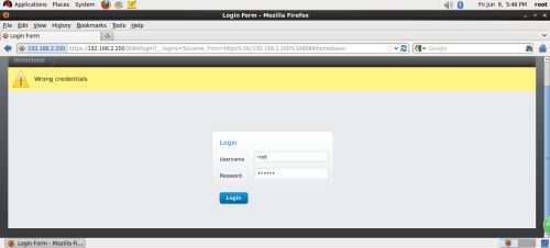
在redhat6中,luci的登录用户名和密码与root账号相同。而在redhat5中需要通过
#luci_admin init(没有亲测)来进行初始化然后再设置密码,输入两次密码后,就会默认创建一个登录luci的用户admin。有时候会在登录界面左上角出现wrong credentials的叹号提示,此时可以通过重新安装luci的方式来解决该问题。
登录成功后的界面
创建集群
Download Packages:表示在线下载并自动安装RHCS软件包。
Use Locally Installed Packages:表示利用本地安装包进行安装。由于之前已经手动安装了RHCS的相关组件,所以这里可以选择该选项。
Enable Shared Storage Support:表示启动共享存储支持。
Reboot Nodes Before Joining Cluster:当节点加入集群时,重启系统。
出现该错误界面,修改ricci密码之后重新启动ricci即可消除。
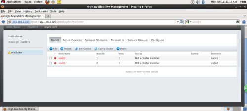
出现错误提示:不是集群节点。出现该现象通常为cman、rgmanager没有启动导致。在启动cman过程中会一直报错,此时需要将NetworkManager关闭再次重启cman服务即可。
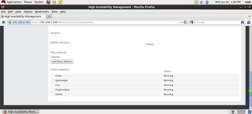
出现如上图所示的效果表示rhcs创建成功。(但一个节点显示uptime另一个不显示,通过点击node1/node2两个节点来查看节点启动的相关服务,会发现节点启动的服务不一致)
最终出现上图所示的状态,说明两节点所有服务启动正常。
注意:
在集群节点加入cluster之后,个别服务可能没有启动,因此需要执行下面命令。
#/etc/init.d/rgmanager start
#/etc/init.d/modclusterd start à如果该服务没有启动,则在uptime一栏显示为空
#/etc/init.d/clvmd start
#/etc/init.d/cman start
#chkconfig rgmanager on
#chkconfig modclusterd on
#chkconfig clvmd on
#chkconfig cman on
2.6.3.1)集群验证
通过上面的步骤最终完成了集群的创建,此时可以通过分别在node1/node2上执行命令查看集群是否配置成功。
[root@node1 ~]# clustat
Cluster Status for cluster_test @ Mon Jul10 23:19:27 2017
Member Status: Quorate
Member Name ID Status
------ ---- ---- ------
node1 1 Online, Local
node2 2 Online
[root@node2 ~]# clustat
Cluster Status for cluster_test @ Mon Jul10 23:19:16 2017
Member Status: Quorate
Member Name ID Status
------ ---- ---- ------
node1 1 Online
node2 2 Online, Local
2.6.4)添加服务
2.6.4.1)添加fence
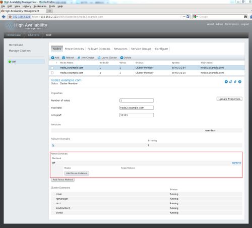
注:在该步骤中node2.example.com对应上面环境中提到的node1。node3.example.com对应上面环境中提到的node2。192.168.2.121对应上面环境中提到的192.168.2.200.(由于实验是通过几次完成的,期间涉及到实验环境重置)
返回到nodes标签下,选中其中一个节点(如node2.example.com),就会出现该节点的详情信息。然后再点击add fence method。
注意:添加的method name为刚才创建的fence。
此时可以看到创建的fence已经被一个节点使用。
按照同样的方法将刚刚创建的fence设备添加到集群中的另一个节点上。最终显示的效果如下:
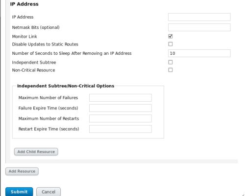
2.6.4.2)添加漂移IP(虚拟IP)
点击luci页面上的Resource,选择IP Address,注意:Netmask Bits必须是掩码位(8、16、24)类型,不能是255.255.255.0,否则服务不能启动。
2.6.4.3)添加Apache资源
点击luci页面上的Resource,通常luci添加资源界面会有很多既定的资源选项,此时选择apache(如果碰到没有的选项则需要选择script,指定个名字,还有脚本路径即可。此实验中尝试选择apache后发现添加的service groups总是failed,因此最终选择添加script方式。如下图所示)。
在添加完成httpd服务之后,需要在apache的配置文件下/etc/httpd/conf/httpd.conf进行相关的更改,此例做的更改如下:
[root@node1 conf]# pwd
/etc/httpd/conf
[root@node1 conf]# ls
httpd.conf magic
[root@node1 conf]# vim httpd.conf à在配置文件的最末尾添加标红字符,node2节点同理
……
DocumentRoot /var/www/html/
ServerName node1.example.com
在每个节点的/var/www/html目录下创建index.html,且在index.html下编写相关文字。
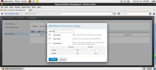
2.6.4.4)添加Failover Domain
将两个节点加入fa失效域,当node1出现问题,服务将切换到node2上,默认服务启动在node1上,因为数字越小,优先级越高。
Prioritized 设定节点优先级
Restricted 指定运行某服务的节点主机
No Failback 勾选时,优先级高的节点主机宕机服务转移到其他节点,其恢复后,服务不再转移到该节点。
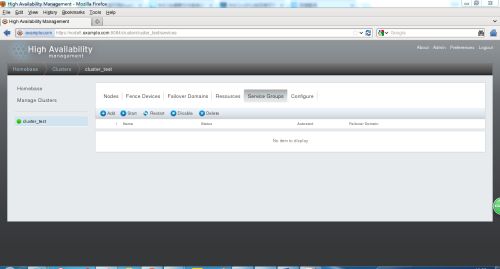
2.6.4.5)添加Service Groups
输入一个服务名user-test,Automatically Start This Service 自动启动服务,将FailoverDomain设置为fa,点击Add resource添加刚才加的资源。
Run Exclusive 专一的运行这一种service
Recovery Policy选择Relocate,服务节点出现问题,转移服务至其它节点。
2.6.4.5.1)添加Resource到service groups
添加vip以及httpd服务
然后服务组会自动运行在优先级高的节点机上,node1的优先级为1,node2的优先级为10,数字越小优先级越高。
2.6.4.6)验证配置结果
在node1上查看集群状态
[root@node1 ~]# clustat
Cluster Status for mycluster @ Mon Jun 1202:24:52 2017
Member Status: Quorate
Member Name ID Status
------ ---- ---- ------
node1 1Online, Local, rgmanager
node2 2 Online, rgmanager
Service Name Owner(Last) State
------- ---- ----- ------ -----
service:userzr-ser node1 started
查看漂移IP所在的位置
[root@node1 ~]# ip addr show
1: lo:
link/loopback 00:00:00:00:00:00 brd 00:00:00:00:00:00
inet 127.0.0.1/8 scope host lo
inet6 ::1/128 scope host
valid_lft forever preferred_lft forever
2: eth0:
link/ether 00:0c:29:e8:16:46 brd ff:ff:ff:ff:ff:ff
inet 192.168.2.103/24 brd 192.168.2.255 scope global eth0
inet 192.168.2.110/24 scope global secondary eth0
inet6 fe80::20c:29ff:fee8:1646/64 scope link
valid_lft forever preferred_lft forever
3: eth1:
link/ether 00:0c:29:e8:16:50 brd ff:ff:ff:ff:ff:ff
inet 10.0.0.2/24 brd 10.0.0.255 scope global eth1
inet6 fe80::20c:29ff:fee8:1650/64 scope link
valid_lft forever preferred_lft forever
4: pan0:
link/ether22:8c:60:ee:9f:24 brd ff:ff:ff:ff:ff:ff
查看httpd服务是否启动
当集群的owner(last)是哪个节点,则哪个节点上的相关服务就被启动,此例子中的服务是httpd。
[root@node1 ~]# /etc/init.d/httpd status
httpd (pid 19276) is running...
2.6.5)挂载文件系统
在客户端设置完initiatorname.iscsi之后,执行如下命令即可:
# iscsiadm -m discovery -t sendtargets -p xxx(ip地址)
#iscsiadm -m node
# iscsiadm -m node -T iqn.2017-05.com.example:node5(iqn号码自定义) --login
最终就会在系统下发现相关的分区
[root@node1 ~]# fdisk -l
Disk /dev/sda: 21.5 GB, 21474836480 bytes
255 heads, 63 sectors/track, 2610 cylinders
Units = cylinders of 16065 * 512 = 8225280 bytes
Sector size (logical/physical): 512 bytes / 512 bytes
I/O size (minimum/optimal): 512 bytes / 512 bytes
Disk identifier: 0x000d5cd9
Device Boot Start End Blocks Id System
/dev/sda1 * 1 39 307200 83 Linux
Partition 1 does not end on cylinder boundary.
/dev/sda2 39 2342 18500608 83 Linux
/dev/sda3 2342 2611 2162688 82 Linux swap / Solaris
Disk /dev/sdb: 21.5 GB, 21474836480 bytes
64 heads, 32 sectors/track, 20480 cylinders
Units = cylinders of 2048 * 512 = 1048576 bytes
Sector size (logical/physical): 512 bytes / 512 bytes
I/O size (minimum/optimal): 512 bytes / 512 bytes
Disk identifier: 0xb58b5eff
Device Boot Start End Blocks Id System
/dev/sdb1 1 1025 1049584 83 Linux
/dev/sdb2 1026 20480 19921920 83 Linux
此时可以看出sdb为新发现的磁盘。且分了两个分区。
2.6.6)集群文件系统的创建
CLVM的作用类似与LVM,但集群文件系统后期如果有规划在线扩容的操作必须要开启clvmd(分发逻辑卷的状态更新<一个节点上操作磁盘分区成功后、另一个节点上也会发生同样的效果变化>)这个功能。
[root@node1 ~]# lvmconf #查看帮助选项
usage: /sbin/lvmconf
Commands:
Enable clvm: --enable-cluster [--lockinglibdir
Disable clvm: --disable-cluster
Set locking library: --lockinglibdir
Global options:
Config file location: --file
[root@node1 ~]# lvmconf --enable-cluster 使逻辑卷支持cluster,分别在node1/2执行
[root@node1 ~]# /etc/init.d/clvmd restart 两个节点都执行。作用:只需在一个节点上执行逻辑卷操作,所有节点同步
Restarting clvmd: [OK ]
将新“映射”到node1/node2的磁盘(sdb)进行分区,在一台机器上做,另一台也会出现创建的分区。
分别在node1/node2上创建pv。
[root@node1 ~]# pvcreate /dev/sdb2
Physical volume"/dev/sdb2" successfully created
[root@node2 ~]# pvcreate /dev/sdb2
Physical volume"/dev/sdb2" successfully created
注意:如果在一个节点上没有运行clvmd服务,则创建pv会出现告警。
[root@node2 ~]# pvs
clvmd not running onnode node2
Unable to obtain globallock.
[root@node1 ~]# vgcreate --help
vgcreate: Create avolume group
vgcreate
[-A|--autobackup{y|n}]
[--addtag Tag]
[--alloc AllocationPolicy]
[-c|--clustered{y|n}]
[-d|--debug]
[-h|--help]
[-l|--maxlogicalvolumesMaxLogicalVolumes]
[-M|--metadatatype1|2]
[--[vg]metadatacopies#copies]
[-p|--maxphysicalvolumesMaxPhysicalVolumes]
[-s|--physicalextentsizePhysicalExtentSize[bBsSkKmMgGtTpPeE]]
[-t|--test]
[-v|--verbose]
[--version]
[ PHYSICAL DEVICEOPTIONS ]
VolumeGroupNamePhysicalDevicePath [PhysicalDevicePath...]
c 支持集群功能,y---yes , n---no
[root@node1 ~]# vgcreate -cy clustervg /dev/sdb2
Clustered volume group"clustervg" successfully created
(如果仅仅在node1上创建pv然后就直接在node1上创建vg/lv,会提示报错:
Error locking on node node2: Volume group for uuid not found:d4EUWKtp6A37RownBShXDrj00ZuZYm7MdUJgXHMZTZ5CFXemlhEfJc1DrVJhHyMU
Failed to activate newLV.)
[root@node1 ~]# lvcreate -l 4863 -n clusterlv clustervg
Logical volume"clusterlv" created
2.6.6.1)创建GFS文件系统
#cat /etc/cluster/cluster.conf #查看集群的名称
[root@node1 /]# cman_tool status #查看集群相关信息,其中涉及到集群名称
Version: 6.2.0
Config Version: 7
Cluster Name: cluster_test
Cluster Id: 42965
Cluster Member: Yes
Cluster Generation: 148
Membership state: Cluster-Member
Nodes: 2
Expected votes: 1
Total votes: 2
Node votes: 1
Quorum: 1
Active subsystems: 9
Flags: 2node
Ports Bound: 0 11 177
Node name: node1
Node ID: 1
Multicast addresses: 239.192.167.125
Node addresses: 192.168.2.103
格式化文件系统
[root@node1 /]# mkfs.gfs2 -p lock_dlm -t cluster_test:gfs -j 3/dev/clustervg/clusterlv
This will destroy any data on /dev/clustervg/clusterlv.
It appears to contain: symbolic link to `../dm-0'
Are you sure you want to proceed? [y/n] y
Device: /dev/clustervg/clusterlv
Blocksize: 4096
Device Size 19.00 GB (4979712 blocks)
Filesystem Size: 19.00 GB (4979711 blocks)
Journals: 3
Resource Groups: 76
Locking Protocol: "lock_dlm"
Lock Table: "cluster_test:gfs"
UUID: 4561c8ab-66a6-c41a-d95c-38ce9314b516
格式话完成之后,在系统下可以出现如下所示的效果:
[root@node1 conf]# blkid
/dev/sda1: UUID="797995cc-52d1-4a15-b38b-b522ad8ede2d"TYPE="ext4"
/dev/sda2:UUID="wtLL6x-4JQJ-X3VL-3QKM-jF1u-f5YX-IfuXnM"TYPE="LVM2_member"
/dev/mapper/VolGroup-lv_root:UUID="7b7c269f-aa59-446f-b610-087438bce9d5" TYPE="ext4"
/dev/mapper/VolGroup-lv_swap:UUID="f06cd436-49fa-4ad6-b6e1-ccc896187d9f" TYPE="swap"
/dev/sdb2: UUID="7hRtF5-WfJo-RRcv-luEx-IdkC-Zho8-RPL2x2"TYPE="LVM2_member"
/dev/mapper/clustervg-clusterlv: LABEL="test:gfs"UUID="ca9baac8-413b-cd0a-a7b6-1ccf6d0f652b" TYPE="gfs2"
注意:
如果出现上述结果,说明文件系统格式化完全,sdb2分区所创建的lv被系统完美的识别。但另外一个节点会存在没有上述红色字体所示的效果,此时可以将该节点reboot。
通过将新建的lv临时挂载在本地的某个目录下来验证新建的lv是否已经生效,同时挂载后还能查看文件系统格式是否正确。验证之后再将lv卸载掉。
在node1上挂载新建的LV
[root@node1 /]# mount /dev/clustervg/clusterlv /data/à在node2上执行同样操作
[root@node1 /]# df -hT
Filesystem Type Size Used Avail Use% Mounted on
/dev/sda2 ext4 18G 2.5G 15G 15% /
tmpfs tmpfs 491M 32M 460M 7% /dev/shm
/dev/sda1 ext4 291M 33M 243M 12% /boot
/dev/sr0 iso9660 3.5G 3.5G 0 100% /mnt/cdrom
/dev/mapper/clustervg-clusterlv
gfs2 19G 388M 19G 2% /data
2.6.6.2)添加gfs文件系统资源
将文件系统资源添加到servicegroups,是的文件系统in use显示为勾。
2.6.7)仲裁盘
[root@node1 ~]# mkqdisk --help
mkqdisk v3.0.12.1
mkqdisk: invalid option -- '-'
mkqdisk: invalid option -- 'e'
mkqdisk: invalid option -- '-'
usage: mkqdisk -L | -f
[root@node1 ~]# mkqdisk -c /dev/sdb1 -l myqdisk
mkqdisk v3.0.12.1
Writing new quorum disk label 'myqdisk' to /dev/sdb1.
WARNING: About to destroy all data on /dev/sdb1; proceed [N/y] ?y
Initializing status block for node 1...
Initializing status block for node 2...
Initializing status block for node 3...
Initializing status block for node 4...
Initializing status block for node 5...
Initializing status block for node 6...
Initializing status block for node 7...
Initializing status block for node 8...
Initializing status block for node 9...
Initializing status block for node 10...
Initializing status block for node 11...
Initializing status block for node 12...
Initializing status block for node 13...
Initializing status block for node 14...
Initializing status block for node 15...
Initializing status block for node 16...
验证是否创建成功
[root@node1 ~]# mkqdisk -L
mkqdisk v3.0.12.1
/dev/block/8:17:
/dev/disk/by-id/scsi-1IET_00010001-part1:
/dev/disk/by-path/ip-192.168.2.200:3260-iscsi-iqn.2017-6.com.example:node5-lun-1-part1:
/dev/disk/by-uuid/f57a4f43-b2df-492c-893d-6b251ff4ae22:
/dev/sdb1:
Magic: eb7a62c2
Label: myqdisk
Created: Tue Jul 18 15:30:50 2017
Host: node1
Kernel SectorSize: 512
Recorded SectorSize: 512
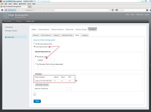
仲裁盘的配置
查看仲裁盘配置是否成功
启动仲裁服务
[root@node1 ~]# /usr/sbin/qdiskd status
QDisk services already running
qdisk启动后,如果配置正确,qdisk磁盘将自动进入online状态,相关信息如下:
[root@node1 ~]# clustat -l
Cluster Status for cluster_test @ Tue Jul 18 17:24:39 2017
Member Status: Quorate
Member Name ID Status
------ ---- ---- ------
node1 1 Online, Local,rgmanager
node2 2 Online, rgmanager
/dev/block/8:17 0 Online, QuorumDisk
Service Information
------- -----------
Service Name :service:user_cluster
Current State : started (112)
Flags : none (0)
Owner : node1
Last Owner : node2
Last Transition : TueJul 18 16:38:26 2017
此时qdisk已经开始运行。
2.7)集群测试
手动切换节点
[root@node2 html]# clusvcadm -r user-test -m node3.example.com
模拟一个节点宕机
在另外一个节点上查看日志文件
[root@node3 log]# tail -f messages
Aug 3 16:21:16 node3 kernel: GFS2: fsid=test:gfs.0: Joined cluster. Nowmounting FS...
Aug 3 16:21:16 node3 kernel: GFS2: fsid=test:gfs.0: jid=0, already lockedfor use
Aug 3 16:21:16 node3 kernel: GFS2: fsid=test:gfs.0: jid=0: Looking atjournal...
Aug 3 16:21:16 node3 kernel: GFS2: fsid=test:gfs.0: jid=0: Done
Aug 3 16:21:16 node3 kernel: GFS2: fsid=test:gfs.0: jid=1: Trying to acquirejournal lock...
Aug 3 16:21:16 node3 kernel: GFS2: fsid=test:gfs.0: jid=1: Looking atjournal...
Aug 3 16:21:16 node3 kernel: GFS2: fsid=test:gfs.0: jid=1: Done
Aug 3 16:21:16 node3 rgmanager[24184]: [ip]Adding IPv4 address 192.168.2.110/24 to eth0
Aug 3 16:21:20 node3 rgmanager[24270]: [script] Executing /etc/init.d/httpdstart
Aug 3 16:21:20 node3 rgmanager[2323]: Serviceservice:user-test started
Aug 3 16:21:38 node3 qdiskd[1625]: Node 1shutdown
Aug 3 16:21:39 node3 kernel: dlm: closing connection to node 1
Aug 3 16:21:39 node3 corosync[1575]: [QUORUM] Members[1]: 2
Aug 3 16:21:39 node3 corosync[1575]: [TOTEM ] A processor joined or left the membership and a new membershipwas formed.
Aug 3 16:21:39 node3 corosync[1575]: [CPG ] chosen downlist: senderr(0) ip(192.168.2.120) ; members(old:2 left:1)
Aug 3 16:21:39 node3 corosync[1575]: [MAIN ] Completed servicesynchronization, ready to provide service.
Aug 3 16:21:39 node3 dlm_controld[1823]: node_history_cluster_remove nonodeid 1
Aug 3 16:21:39 node3 gfs_controld[1873]: node_history_cluster_remove nonodeid 1
Aug 3 16:21:40 node3 ricci[24325]: Executing '/usr/bin/virsh nodeinfo'
Aug 3 16:21:40 node3 ricci[24327]: Executing'/usr/libexec/ricci/ricci-worker -f /var/lib/ricci/queue/954519272'
Aug 3 16:21:41 node3 ricci[24443]: Executing '/usr/libexec/ricci/ricci-worker-f /var/lib/ricci/queue/2133287837'
Aug 3 16:21:51 node3 rgmanager[24468]: [script] Executing /etc/init.d/httpdstatus
Aug 3 16:22:22 node3 rgmanager[24911]: [script] Executing /etc/init.d/httpdstatus
Aug 3 16:23:01 node3 rgmanager[25205]: [script] Executing /etc/init.d/httpdstatus
[root@node3 log]# clustat
Cluster Status for test @ Thu Aug 3 16:24:13 2017
Member Status: Quorate
Member Name ID Status
------ ---- ---- ------
node2.example.com 1 Offline
node3.example.com 2 Online,Local, rgmanager
/dev/block/8:17 0Online, Quorum Disk
Service Name Owner(Last) State
------- ---- ----- ------ -----
service:user-test node3.example.com started
通过以上两种测试方法,可以发现即使一个节点宕机也不会妨碍服务的正常运行。
2.6.8)总结
由于设备的限制,没有真实的fence。实验中使用的fence是通过参考网络上的资料(http://zaizai1573.blog.51cto.com/4515471/1564605)所得知。通过查找相关资料发现存在多种fence但是由于条件的限制以及个人知识的局限,仅仅通过了上面的步骤将搭建环境还原,如有问题请指正。
