先上图:
**
点子来自于一次情人节的礼物思考,想着能不能不俗套的去送花发红包之类的,再加上妹子也是做技术的,所以就想着搞了一个这个。
**
**
这个效果的原理是基于PathView的,可是PathView并不能满足我的需求,于是乎我就开始下手自己修改了。
**
**
下面我会一边分析PathView的实现过程,一边描述我是如何修改的(GIF图很多小心流量)。如果你不想看的话项目地址在这
https://github.com/MartinBZDQSM/PathDraw
**
动画效果
如果你了解PathView的动画的话,你就知道它的动画分为两种情况
1.getPathAnimator 并行效果
2.getSequentialPathAnimator 顺序效果
如果你想知道它的实现原理建议查看PathView当中的两个静态内部类AnimatorBuilder和AnimatorSetBuilder。
但是当我使用AnimatorSetBuilder 进行顺序绘制的时候我发现效果其实并不好,为什么不好哪里不好呢?看它的源码:
     /**
         * Sets the duration of the animation. Since the AnimatorSet sets the duration for each
         * Animator, we have to divide it by the number of paths.
         *
         * @param duration - The duration of the animation.
         * @return AnimatorSetBuilder.
         */
        public AnimatorSetBuilder duration(final int duration) {
            this.duration = duration / paths.size();
            return this;
        }
看完以上代码你就会知道PathView的作者计算出来的动画时间是你设置的平均时间,也就是说不管我这条path的路径到底有多长,所有path的执行时间都是一样的。那我画一个点和画一条直线的时间都是一样的是不是有点扯?所以我在这里增加了平均时间的计算,根据计算path的长度在总长度中的占比,然后单个设置时间,进行顺序轮播,我也试过使用AnimatorSet单独设置Animator的时间,但是好像并没有效果,所以我用比较蠢点方法进行了实现,大致修改的代码如下:
        /**
         * Default constructor.
         *
         * @param pathView The view that must be animated.
         */
        public AnimatorSetBuilder(final PathDrawingView pathView) {
            paths = pathView.mPaths;
            if (pathViewAnimatorListener == null) {
                pathViewAnimatorListener = new PathViewAnimatorListener();
            }
            for (PathLayer.SvgPath path : paths) {
                path.setAnimationStepListener(pathView);
                ObjectAnimator animation = ObjectAnimator.ofFloat(path, "length", 0.0f, path.getLength());
                totalLenth = totalLenth + path.getLength();
                animators.add(animation);
            }
            for (int i = 0; i < paths.size(); i++) {
                long animationDuration = (long) (paths.get(i).getLength() * duration / totalLenth);
                Animator animator = animators.get(i);
                animator.setStartDelay(delay);
                animator.setDuration(animationDuration);
                animator.addListener(pathViewAnimatorListener);
            }
        }
        /**
         * Starts the animation.
         */
        public void start() {
            resetAllPaths();
            for (Animator animator : animators) {
                animator.cancel();
            }
            index = 0;
            startAnimatorByIndex();
        }

        public void startAnimatorByIndex() {
            if (index >= paths.size()) {
                return;
            }
            Animator animator = animators.get(index);
            animator.start();
        }

        /**
         * Sets the length of all the paths to 0.
         */
        private void resetAllPaths() {
            for (PathLayer.SvgPath path : paths) {
                path.setLength(0);
            }
        }

        /**
         * Called when the animation start.
         */
        public interface ListenerStart {
            /**
             * Called when the path animation start.
             */
            void onAnimationStart();
        }

        /**
         * Called when the animation end.
         */
        public interface ListenerEnd {
            /**
             * Called when the path animation end.
             */
            void onAnimationEnd();
        }

        /**
         * Animation listener to be able to provide callbacks for the caller.
         */
        private class PathViewAnimatorListener implements Animator.AnimatorListener {

            @Override
            public void onAnimationStart(Animator animation) {
                if (index < paths.size() - 1) {
                    paths.get(index).isMeasure = true;
                    PathDrawingView.isDrawing = true;
                    if (index == 0 && listenerStart != null)
                        listenerStart.onAnimationStart();
                }

            }

            @Override
            public void onAnimationEnd(Animator animation) {
                if (index >= paths.size() - 1) {
                    PathDrawingView.isDrawing = false;
                    if (animationEnd != null)
                        animationEnd.onAnimationEnd();
                } else {
                    if (index < paths.size() - 1) {
                        paths.get(index).isMeasure = false;
                        index++;
                        startAnimatorByIndex();
                    }
                }
            }

            @Override
            public void onAnimationCancel(Animator animation) {

            }

            @Override
            public void onAnimationRepeat(Animator animation) {

            }
        }
画笔动态跟踪
PathView中线条渐变是通过截取path当中的片段做成的,看码:
     /**
         * Sets the length of the path.
         *
         * @param length The length to be set.
         */
        public void setLength(float length) {
            path.reset();
            measure.getSegment(0.0f, length, path, true);
            path.rLineTo(0.0f, 0.0f);

            if (animationStepListener != null) {
                animationStepListener.onAnimationStep();
            }
        }
既然动画的原理是通过改变截取的长度做到的,那么只要能获取到截取长度最后的那个点是不是就可以充当轨迹了?所以这里只需要添加一个锚点,每当截取长度变化的时候,锚点也跟着改变,看代码:
    public void setLength(float length) {
            path.reset();
            measure.getSegment(0.0f, length, path, true);
            measure.getPosTan(length, point, null);//跟踪锚点
            path.rLineTo(0.0f, 0.0f);
            if (animationStepListener != null) {
                animationStepListener.onAnimationStep();
            }
        }
笔尖移动的原理,需要提前计算好笔尖在画笔图片中的坐标,然后对照着锚点进行移动就行了。
Tips:这里我的画笔图片还没有针对画布宽高进行缩放,所以在不同分辨率的情况下画笔显示的大小可能是不一致的。
我认知的Fill
PathView中对于Path的Paint选的是Stroke属性,而如果需要进行填充,则需要所有的线条绘制完成之后才能进行填充或者默认填充。看PathView的源码:
    @Override
    protected void onDraw(Canvas canvas) {
        super.onDraw(canvas);

        if(mTempBitmap==null || (mTempBitmap.getWidth()!=canvas.getWidth()||mTempBitmap.getHeight()!=canvas.getHeight()) )
        {
            mTempBitmap = Bitmap.createBitmap(canvas.getWidth(), canvas.getHeight(), Bitmap.Config.ARGB_8888);
            mTempCanvas = new Canvas(mTempBitmap);
        }

        mTempBitmap.eraseColor(0);
        synchronized (mSvgLock) {
            mTempCanvas.save();
            mTempCanvas.translate(getPaddingLeft(), getPaddingTop());
            fill(mTempCanvas);//直接进行填充
            final int count = paths.size();
            for (int i = 0; i < count; i++) {
                final SvgUtils.SvgPath svgPath = paths.get(i);
                final Path path = svgPath.path;
                final Paint paint1 = naturalColors ? svgPath.paint : paint;
                mTempCanvas.drawPath(path, paint1);
            }

            fillAfter(mTempCanvas);//线条绘制完成之后 在进行填充

            mTempCanvas.restore();

            applySolidColor(mTempBitmap);

            canvas.drawBitmap(mTempBitmap,0,0,null);
        }
    }
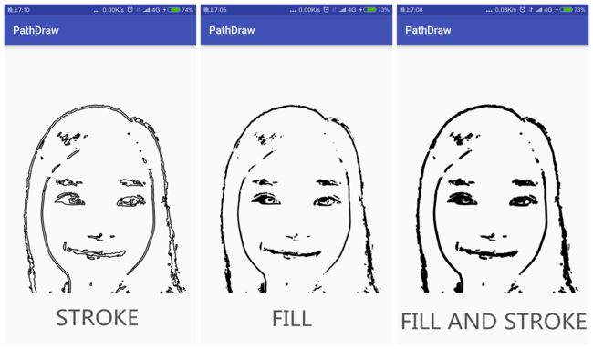
其实这里选Stroke属性还是Fill属性都是看svg的情况而定,针对于我自己做的这个svg图,我对比了三种属性的不同效果,看图:
看了上图我们可以发现,如果我们使用的svg不是由 单线条组成的,会感觉特别怪异,而Fill和Fill And Stroke则显示的较为舒服。更贴近svg在浏览器显示出来的效果。
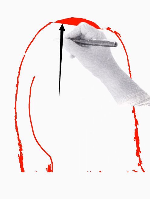
那么问题来了! 如果我们使用Fill 属性或者Fill And Stroke属性,在线条绘制过程中会把所截取的Path的起点和重点连接起来形成一个闭合区域。我把这种情况叫做“绘制过度”(瞎取的),看图:
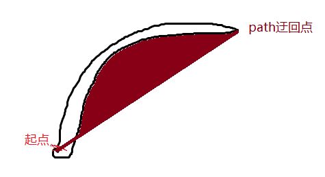
为什么会导致这种情况看我画的这张图你就会明白了;
在path往回绘制的时候,paint并不知道接下来会如何填充,所以就直接连接了迂回点和终点。
那么如何消除Fill属性带来的影响呢?刚开始我想了大致两个思路并进行了尝试:
- 多保留一份Paths,在绘制的时候Clip原path路径。
- 多保留一份Paths,使用PorterDuffXfermode,当绘制的时候显示被绘制的path遮挡的部分。
我先实现了思路1,看我如何实现的:
 @Override
    protected void onDraw(Canvas canvas) {
        super.onDraw(canvas);
        int sc = canvas.save(Canvas.ALL_SAVE_FLAG);
        synchronized (mSvgLock) {
            int count = mPaths.size();
            for (int i = 0; i < count; i++) {
                int pc = canvas.save(Canvas.ALL_SAVE_FLAG);
                //需要备用一个完整的path路径,来修复pathPaint的Fill造成绘制过度
                Path path = pathLayer.mDrawer.get(i);//这个pathLayer 指的就是Pathview中的SvgUtils
                canvas.clipPath(path);
                PathLayer.SvgPath svgPath = mPaths.get(i);
                canvas.drawPath(svgPath.path, pathPaint);
                canvas.restoreToCount(pc);
            }
        }
        canvas.restoreToCount(sc);
        for (PathLayer.SvgPath svgPath : mPaths) {
            if (isDrawing && svgPath.isMeasure) {//过滤初始为0的点
                canvas.drawBitmap(paintLayer, svgPath.point[0] - nibPointf.x, svgPath.point[1] - nibPointf.y, null);
            }
        }
    }
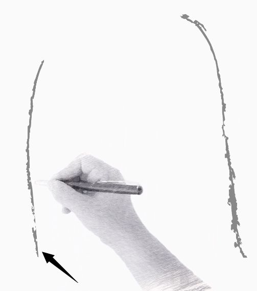
看效果:
仔细看效果发现其实还是有问题存在的,再线条迂回的地方会把遗漏;
为什么会导致这种情况,其实还是前面讲到过的绘制过度。
于是我尝试了下实现下思路2:
    private PorterDuffXfermode xfermode = new PorterDuffXfermode(PorterDuff.Mode.SRC_OUT);

    @Override
    protected void onDraw(Canvas canvas) {
        super.onDraw(canvas);
        int sc = canvas.save(Canvas.ALL_SAVE_FLAG);
        synchronized (mSvgLock) {
            int count = mPaths.size();
            for (int i = 0; i < count; i++) {
                int pc = canvas.save(Canvas.ALL_SAVE_FLAG);
                PathLayer.SvgPath svgPath = mPaths.get(i);
                if (isFill) {
                    //需要备用一个完整的path路径,来修复pathPaint的Fill造成绘制过度
                    Path path = pathLayer.mDrawer.get(i);
                    canvas.clipPath(path);
                    if (isDrawing && svgPath.isMeasure) {
                        canvas.drawPath(path, drawerPaint);
                    }
                }
                canvas.drawPath(svgPath.path, pathPaint);
                canvas.restoreToCount(pc);
            }
        }
        canvas.restoreToCount(sc);
    }
效果如下:
关于为什么要使用PorterDuff.Mode.SRC_OUT,其实我是试出来的0.0,本以为这样就完美了,但是我发现当仔细看发现颜色他么怎么变成黑色了(我用的是灰色)!!!然后我尝试了使用一张Bitmap的Canvas来代替view的Canvas再渲染像素点的颜色的时候,发现效果又乱了!!!!真是奇怪,为了研究原因我将 canvas.clipPath(path);去掉,发现了新大陆,看图:
原来PorterDuff.Mode.SRC_OUT将非覆盖面生成了矩形块,那么新思路就有了:
3.直接截取path的矩形块:
      if (isFill) {
                    //需要备用一个完整的path路径,来修复pathPaint的Fill造成绘制过度
                    Path path = pathLayer.mDrawer.get(i);
                    canvas.clipPath(path);
                    svgPath.path.computeBounds(drawRect, true);
                    canvas.drawRect(drawRect, drawerPaint);
                }
最终效果图就和文章最开始的显示效果一致了,哈哈 几经波折终于出现好效果啦!
如何制作svg
关于如何制作成这样的svg ,你可以考虑看我的文章:《如何将图片生成svg》,使用的是Adobe Illustrator而不是GMIP2
最后,如果你喜欢或者有何意见,不妨Star或者给我提Issuses哦!项目地址
]


