Cisco MIBGP MPLS ×××配置指导
1 BGP/MPLS ×××概述
BGP/MPLS ×××是一种三层×××技术,该技术使用MBGP在骨干网络发布×××V4路由,使用MPLS在骨干网上转发×××报文。三层×××通常部署在运营商或者大型企业网内部,由于其能够比较方便的支持MPLS QoS和TE技术,因此作为企业DCN网络的基本模型得到越来越广泛的应用。
本文主要提供Cisco设备自治系统内的三层×××配置,并对关键点进行简单分析。
2 一些基本概念
如上图,整个三层×××网络主要由CE、PE和P设备这三部分组成;图中的R1和R5为CE设备,即用户网络边缘设备,可以是一个用户网络,也可以是一台路由器,也可以是一台用户主机,对于CE而言,CE感知不到×××的存在,也不需要支持MPLS功能,作为CE,它与PE直连,只需要支持普通IP即可,与PE互通的网络协议可以是EBGP、多实例的IGP或者静态路由,这个是具体情况而言,本文的配置采用EBGP连接PE和CE;图中的R2和R4为PE设备,即服务提供商边缘设备,与CE直连,在三层×××网络中,对于×××的处理都发生在PE上;图中的R3为P设备,即整个网络中的骨干路由器,不与CE直连,P可以和PE连接,也可以和P连接,当然也可以不存在,即整个三层×××网络中只有PE设备,没有P设备,对于P而言,只需要具有基本的MPLS转发能力即可。
RD:Route Distinguisher,RD 用于发布×××路由时区分使用相同地址的IPv4 前缀,比如两个不同的×××均有相同的IPv4前缀,如果不加以区分的话,就不能够正常的通过BGP发布给邻居,这里通过RD和普通的IPv4前缀形成一个新的×××V4的地址,然后通过MBGP发布给对端邻居,从而区分不同×××中的相同地址,这样就可以实现三层×××中地址重叠这一功能。需要注意的是必须保证RD值全局唯一,即不同的×××设置不同的RD。具体的RD格式这里不作详细描述。
RT:Route Target,RT是一种BGP扩展团体属性,用来控制××× 路由信息的发布。由于RD不能用于判断某条路由的发起者,也不能判断某条路由属于哪个×××。这时就需要用到RT,RT用来描述一条×××v4路由可以为哪些×××所接收,以及PE可以接收哪些×××发送来的路由。
3 网络分析
R2、R3和R4之间部署IGP和LDP,R2和R4之间建立MIBG邻居;
R1和R2、R4和R5之间分别建立普通EBGP邻居;
R2和R4上配置vrf,将其与R1和R5直连的链路配置属于该vrf。
4 数据设计
Loopback地址:202.1.1.X/32,X=1、2、3、4、5,即路由器序号;
接口地址:80.X.Y.Z/24,X/Y=路由器序号,Z=1、2,路由器序号小的为1,大的为2;
IGP:PE-P-PE之间部署OSPF和LDP;
AS:R2和R4的AS号为100,R1的AS号为1000,R5的AS号为5000;
Vrf:RT为100:1,RD为100:1。
5 配置步骤
配置LSR的各接口地址;
配置OSPF保证LSR之间可达;
配置MPLS基本能力;
配置MIBGP和EBGP;
配置vrf以及相应的RD、RT。
6 详细配置
为了节约版本,只罗列出5台路由器的相关配置,其他无关配置均不贴出来。
[R1]
R1#show run
!
version 12.4
!
hostname R1
!
ip cef
!
no mpls ip
!
interface Loopback0
ip address 202.1.1.1 255.255.255.255
!
interface Ethernet4/0
ip address 80.1.2.1 255.255.255.0
duplex full
!
router bgp 1000
no synchronization
bgp log-neighbor-changes
redistribute connected
neighbor 80.1.2.2 remote-as 100
no auto-summary
!
end
[R2]
R2#show run
!
version 12.4
!
hostname R2
!
ip cef
!
ip vrf vrf1
rd 100:1
route-target export 100:1
route-target import 100:1
!
interface Loopback0
ip address 202.1.1.2 255.255.255.255
!
interface Ethernet4/0
ip vrf forwarding vrf1
ip address 80.1.2.2 255.255.255.0
duplex full
!
interface Ethernet4/1
ip address 80.2.3.1 255.255.255.0
duplex full
mpls ip
!
router ospf 1
log-adjacency-changes
network 80.1.2.0 0.0.0.255 area 0
network 80.2.3.0 0.0.0.255 area 0
network 202.1.1.2 0.0.0.0 area 0
!
router bgp 100
bgp log-neighbor-changes
neighbor 202.1.1.4 remote-as 100
neighbor 202.1.1.4 update-source Loopback0
!
address-family ipv4
no neighbor 202.1.1.4 activate
no auto-summary
no synchronization
exit-address-family
!
address-family ***v4
neighbor 202.1.1.4 activate
neighbor 202.1.1.4 send-community extended
exit-address-family
!
address-family ipv4 vrf vrf1
redistribute connected
neighbor 80.1.2.1 remote-as 1000
neighbor 80.1.2.1 activate
no synchronization
exit-address-family
!
end
[R3]
R3#show run
!
version 12.4
!
hostname R3
!
ip cef
!
interface Loopback0
ip address 202.1.1.3 255.255.255.255
!
interface Ethernet4/1
ip address 80.2.3.2 255.255.255.0
duplex full
mpls ip
!
interface Ethernet4/2
ip address 80.3.4.1 255.255.255.0
duplex half
mpls ip
!
router ospf 1
log-adjacency-changes
network 80.1.3.0 0.0.0.255 area 0
network 80.2.3.0 0.0.0.255 area 0
network 80.3.4.0 0.0.0.255 area 0
network 202.1.1.3 0.0.0.0 area 0
!
end
[R4]
R4#show run
!
version 12.4
!
hostname R4
!
ip cef
!
ip vrf vrf1
rd 100:1
route-target export 100:1
route-target import 100:1
!
interface Loopback0
ip address 202.1.1.4 255.255.255.255
!
interface Ethernet4/2
ip address 80.3.4.2 255.255.255.0
duplex half
mpls ip
!
interface Ethernet4/3
ip vrf forwarding vrf1
ip address 80.4.5.1 255.255.255.0
duplex half
!
router ospf 1
log-adjacency-changes
network 80.3.4.0 0.0.0.255 area 0
network 80.4.5.0 0.0.0.255 area 0
network 202.1.1.4 0.0.0.0 area 0
!
router bgp 100
bgp log-neighbor-changes
neighbor 202.1.1.2 remote-as 100
neighbor 202.1.1.2 update-source Loopback0
!
address-family ipv4
no neighbor 202.1.1.2 activate
no auto-summary
no synchronization
exit-address-family
!
address-family ***v4
neighbor 202.1.1.2 activate
neighbor 202.1.1.2 send-community extended
exit-address-family
!
address-family ipv4 vrf vrf1
neighbor 80.4.5.2 remote-as 5000
neighbor 80.4.5.2 activate
no synchronization
exit-address-family
!
end
[R5]
R5#
R5#show run
!
version 12.4
!
hostname R5
!
ip cef
!
no mpls ip
!
interface Loopback0
ip address 202.1.1.5 255.255.255.255
!
interface Ethernet4/3
ip address 80.4.5.2 255.255.255.0
duplex half
!
router bgp 5000
no synchronization
bgp log-neighbor-changes
redistribute connected
neighbor 80.4.5.1 remote-as 100
no auto-summary
!
end
R5#
7 显示信息
BGP
邻居的建立
在R2上显示BGP邻居可以看出,R2和R1建立EBGP邻居,和R4建立MIBGP邻居:
R2#show bgp ***v4 unicast all neighbors
BGP neighbor is 80.1.2.1, vrf vrf1, remote AS 1000, external link
BGP version 4, remote router ID 202.1.1.1
BGP state = Established, up for 00:57:54
Last read 00:00:55, last write 00:00:55, hold time is 180, keepalive interval
is 60 seconds
Neighbor capabilities:
Route refresh: advertised and received(old & new)
Address family IPv4 Unicast: advertised and received
BGP neighbor is 202.1.1.4, remote AS 100, internal link
BGP version 4, remote router ID 202.1.1.4
BGP state = Established, up for 00:56:46
Last read 00:00:46, last write 00:00:46, hold time is 180, keepalive interval
is 60 seconds
Neighbor capabilities:
Route refresh: advertised and received(old & new)
Address family ×××v4 Unicast: advertised and received
当BGP邻居建立好之后,此时R2已经能够学习到×××V4路由,如下:
R2#show ip route vrf vrf1
Routing Table: vrf1
Codes: C - connected, S - static, R - RIP, M - mobile, B - BGP
D - EIGRP, EX - EIGRP external, O - OSPF, IA - OSPF inter area
N1 - OSPF NSSA external type 1, N2 - OSPF NSSA external type 2
E1 - OSPF external type 1, E2 - OSPF external type 2
i - IS-IS, su - IS-IS summary, L1 - IS-IS level-1, L2 - IS-IS level-2
ia - IS-IS inter area, * - candidate default, U - per-user static route
o - ODR, P - periodic downloaded static route
Gateway of last resort is not set
80.0.0.0/24 is subnetted, 2 subnets
B 80.4.5.0 [200/0] via 202.1.1.4, 00:57:58
C 80.1.2.0 is directly connected, Ethernet4/0
202.1.1.0/32 is subnetted, 2 subnets
B 202.1.1.1 [20/0] via 80.1.2.1, 00:59:13
B 202.1.1.5 [200/0] via 202.1.1.4, 00:57:58
R1和R5上也有各自的路由信息了,但是此时如果在R1上ping R5,却不能通,为什么?因为BGP只是用于信令层面上的路由信息的发布,要打通转发层面,必须在R2-R3-R4之间配置LDP。
公网标签和私网标签
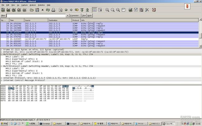
在完全做好配置之后,我们可以在R2和R4上看到公网标签和私网标签,公网标签是由LDP触发的,由于指导×××数据报文在MPLS域中转发,而私网标签则是由MBGP触发的,用于指导×××数据在私网×××中的转发,这一点在跨域的三层×××中体现的比较明显。从公网和私网标签的简单分析,我们可以看出×××中的数据转发时,是携带了两层MPLS标签的,即内层标签为私网标签,外层标签为公网标签,这里我们可以通过显示标签信息和捕获数据报文映射对比一下。
在R4上显示LDP公网标签,可以看出R4到R2出标签为16:
R4#show mpls forwarding-table
Local Outgoing Prefix Bytes tag Outgoing Next Hop
tag tag or VC or Tunnel Id switched interface
16 Pop tag 80.2.3.0/24 0 Et4/2 80.3.4.1
17 16 202.1.1.2/32 0 Et4/2 80.3.4.1
18 Pop tag 202.1.1.3/32 0 Et4/2 80.3.4.1
19 Untagged 202.1.1.5/32[V] 3420 Et4/3 80.4.5.2
20 Aggregate 80.4.5.0/24[V] 0
R4#
在R4上显示MBGP私网标签,可以看出到R1的出标签为19:
R4#show bgp ***v4 unicast all labels
NetworkNext Hop In label/Out label
Route Distinguisher: 100:1 (vrf1)
80.1.2.0/24 202.1.1.2 nolabel/18
80.4.5.0/24 80.4.5.2 20/aggregate(vrf1)
202.1.1.1/32 202.1.1.2 nolabel/19
202.1.1.5/32 80.4.5.2 19/nolabel
那么正常的从R5到R1的×××数据的标签头就应该是
16|19,从下面捕获的报文中我们就可以看出确实如此:
总结:本文写的不是很详细,唯有配置最完整,用以提供给有一定基础的兄弟参考,网络这个东西不能闭门造车,沟通越多提高越快。

