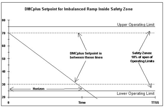
失衡斜坡的当前值在安全区域内时代表了第二种可能性(参见图28)。如果斜坡当前值在上安全区域内,允许失衡高线斜率为0。
允许失衡低线以当前值为起点,下安全区域与时域交点为终点,两点间的连线组成(如上述所示)。这条线的斜率是失衡下限。换句话说,稳态优化可以让液位下降,但不会让液位升高。
DMCplus动作计算的设定点不是基于当前值,而是基于触犯安全区域。设定值是一条起始于触犯安全区域,斜率等于稳态计算失衡延伸向未来的线(见图29)。如果计算出的稳态失衡触碰到失衡高限(即斜坡平衡),则上部安全区域即是设定值。
图28:安全区域内失衡斜坡
图29:安全区域内失衡斜坡的DMCplus设定值
第三种可能性是失衡斜坡当前值违反了操作限制(见图30)。如果当前值违反了操作上限,允许失衡线的计算方法如下:允许失衡高线以当前值为起点,上操作限与时域交点为另一点的射线组成。允许失衡低线以当前值为起点,下安全区域边界与时域交点为另一点的射线组成。
由于当前值在安全区域外,其会积极驱动往回走以消除安全区限制。DMCplus动作计算的设定点依旧基于触碰安全区域,而非当前值(见图31)。设定值是一条以当前安全区域界限为起点,斜率与稳态失衡计算一样的射线。
图30:操作限制外的失衡斜坡
图31:操作限制外的失衡斜坡DMCplus设定值
用于指定时域的参数RHORIZ,不能小于稳态时间的1/3,但根据需要可以足够大。该参数越小,斜坡将越迅速地驱向操作界限。
1/3的限制体现了失衡斜坡将在1/3的稳态时间内被驱动至安全区域。这样的RHORIZ是一个非常强的设置。通常,该数字应该至少与稳态时间一样大。如果库存是相当小的,那么鉴于少数失衡周期就可能导致液位驱动至区域之外,将不被允许运行失衡周期。
如果计算出的稳态失衡超出允许失衡限制,DMCplus控制将被中断,即使指定的连续失衡控制周期数尚未达到。
综上所述,稳态优化尝试平衡斜坡。如果它能平衡斜坡,DMCplus设定值将按照传统方式计算。如果稳态优化不能平衡斜坡并且MXNIMB= 0,控制将中止。
如果MXNIMB>0,将对失衡量进行核对以确定是否超过最大失衡限制。如果失衡量超过这些限制,控制将被中止。如果失衡量在这些限制内,则控制器被允许在失衡情况下继续运行“MXNIMB”个连续控制周期(但在允许失衡限制内)。
如果DMCplus控制器无法平衡斜坡并在“MXNIMB+ 1”的连续周期处于失衡状态,那么DMCplus控制被中止。允许的失衡限制在每个控制周期内基于当前值(如前所述)进行更新,因此当前值接近操作限制时,在该方向上失衡允许量将减少。
允许少数几个周期失衡状态下运行的功能对噪音信号特别有用,因为噪音尖峰可能会阻止稳态优化消除失衡,而等待一个或几个周期后这个问题就能解决。
这种功能被证明对有限库存容器也非常有用,因为几个周期的失衡不会有任何负面影响。有一点需要注意:当线性规划不能完全消除失衡时,其依然在MV的约束范围内使失衡尽可能小。换句话说,失衡优选值是零。这不同于程序控制失衡斜坡,后者失衡可以在任何允许失衡限制的范围内,而没有优选值(接下来讨论)。
附原文:
An imbalanced ramp with its current value inside the Safety Zone represents the second possibility (see Figure 28). If the current value of a ramp is inside the upper Safety Zone, the upper allowed imbalance is zero.
The lower allowed imbalance line is constructed (as above) by drawing a line from the current value to intersect with the lower Safety Zone at the end of the Horizon. The slope of this line isthe lower limit on imbalance. In other words, the steady-state optimization might let the level fall, but might not let the level rise.
The setpoint for the DMCplus move calculation is not based on the current value, but instead on the violated Safety Zone. The setpoint is a line starting at the value of the violated Safety Zone and extending into the future, with a slope equal to the steady-state calculated imbalance (see Figure 29). If the steady-state calculated imbalance is against the upper imbalance limit (i.e., the ramp is balanced), then the upper safety zone is the setpoint.
An imbalanced ramp with its current value in violation of an operating limit is the third possibility (see Figure 30). If the current value is in violation of the upper the operating limit, the allowed imbalance lines are calculated as follows:The upper allowed imbalance line is constructed by drawing a line from the current value to intersect with the upper operating limit at the end of the Horizon. The lower allowed imbalance line is constructed by drawing a line from the current value to the Lower Safety Zone at the end of the Horizon.
Since the current value is outside the Safety Zone, it is actively driven back toward the violated Safety Zone limit. The setpoint for the DMCplus move calculation is again based on the violated Safety Zone, and not on the current value (see Figure 31). The setpoint is a line starting at the violated Safety Zone and extending into the future with a slope equal to the steady-state calculated imbalance.
The parameter RHORIZ, which is used to specify the Horizon, cannot be less that 1/3, but can be as large as desired. The smaller this parameter, the more rapidly the ramp may be driven toward the operating limits.
The 1/3 limit reflects an imbalance that would drive the ramp to the safety zone in 1/3 of the steady-state time. This would be a very aggressive setting for RHORIZ. Generally, this number should be at least as large as the steady-state time. If the inventory is fairly small, then no imbalance should be allowed since even a few cycles of imbalance could drive the level outside the transmitter range.
If the steady-state calculated imbalance is outside the allowed imbalance limits, DMCplus control is aborted,even if the specified number of consecutive imbalanced control cycles has not been reached.
In summary, the steady-state optimization attempts to balance the ramp. If it can balance the ramp, then theDMCplus setpoint is calculated in the traditional way. If the steady-state optimization cannot balance the ramp, and MXNIMB=0, then control is aborted.
If MXNIMB>0, the amount of imbalance is checked against the maximum allowed imbalance limits.If the amount of imbalance exceeds these limits, then control is aborted. If the amount of imbalance is within these limits, then the controller is allowed to remain on for as many as 'MXNIMB' consecutive control cycles out of balance (but within the allowed imbalance limits).
If the DMCplus controller is unable to balance the ramp on 'MXNIMB+1' consecutive interval out of balance,then DMCplus control is aborted. The allowed imbalance limits are updated atevery control interval, based on the current value (described previously), so as the current value approaches an operating limit, the amount of imbalance allowed in that direction decreases.
The ability to allow a few cycles out of balance should be particularly useful on noisy signals, where a noise spike might prevent the steady-state optimization from being able to eliminate the imbalance, and merely waiting one more interval solves the problem.
This capability should also prove useful on vessels that have a moderate inventory where being out of balance for a few cycles will not create any difficulties.One point to note: when the Linear Program is not able to fully eliminate the imbalance, it has still made the imbalance as small as possible within the confines of the MV constraints. In other words, the preferred imbalance value is zero. This differs from a Programmed Imbalance Ramp, in which the imbalance is allowed to assume any value within the allowed imbalance limits, with no preferred value(discussed next).
2015.10.5


